


What is additive manufacturing or 3D printing?
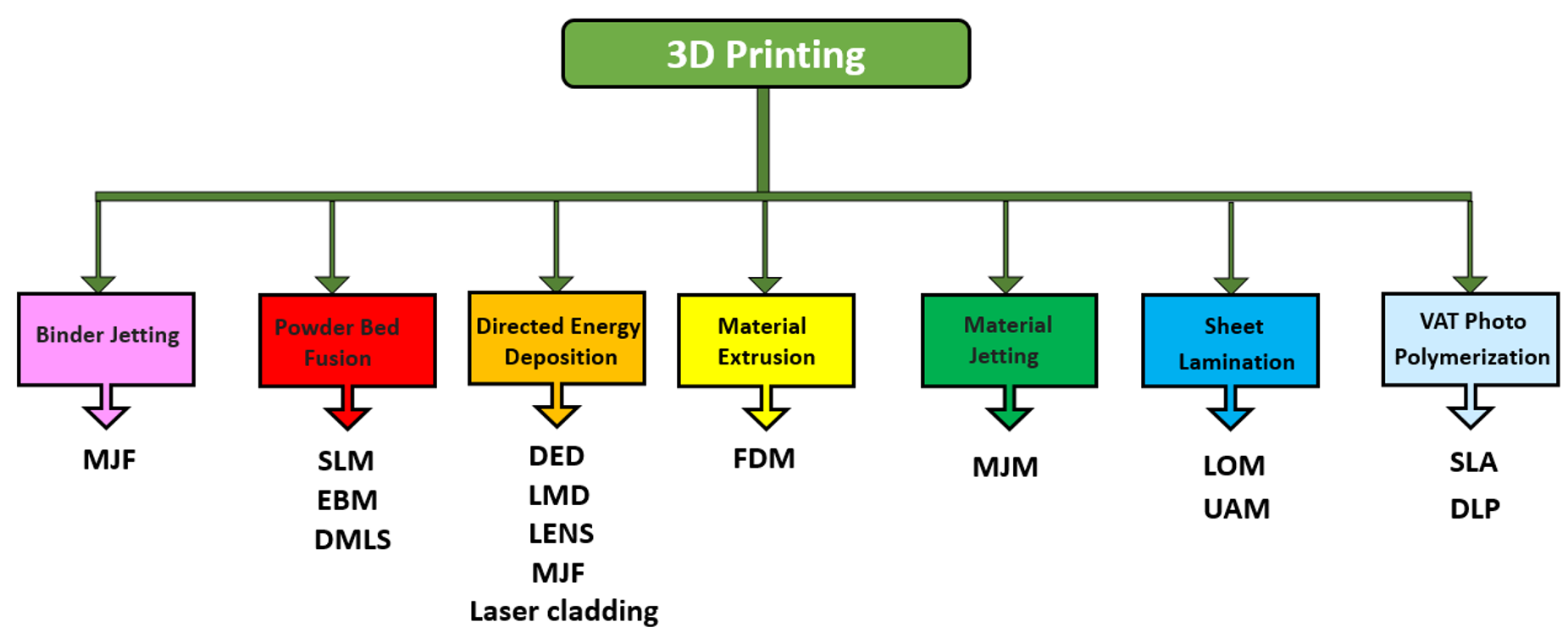
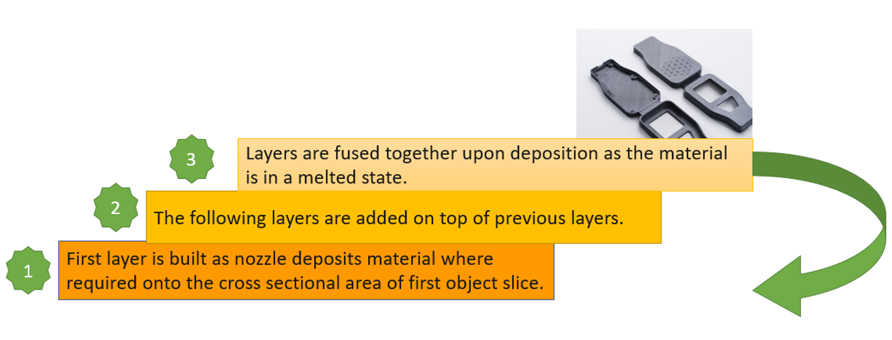
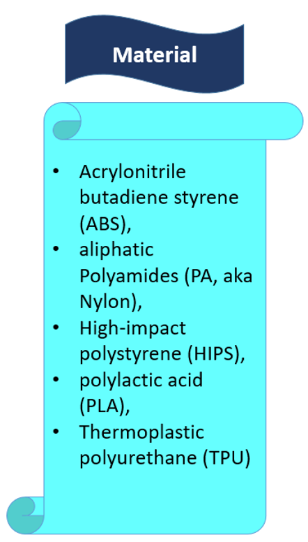
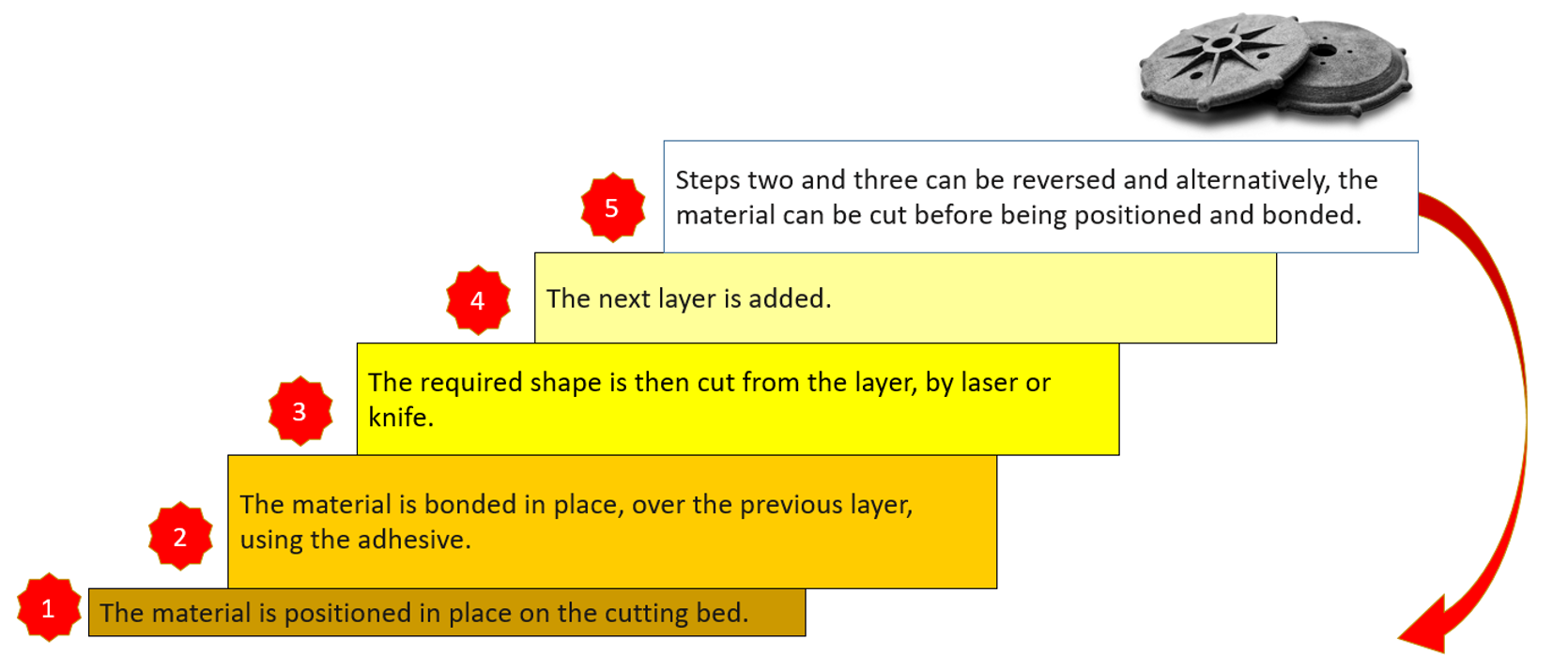
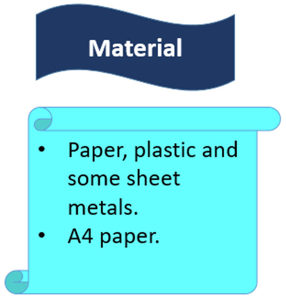
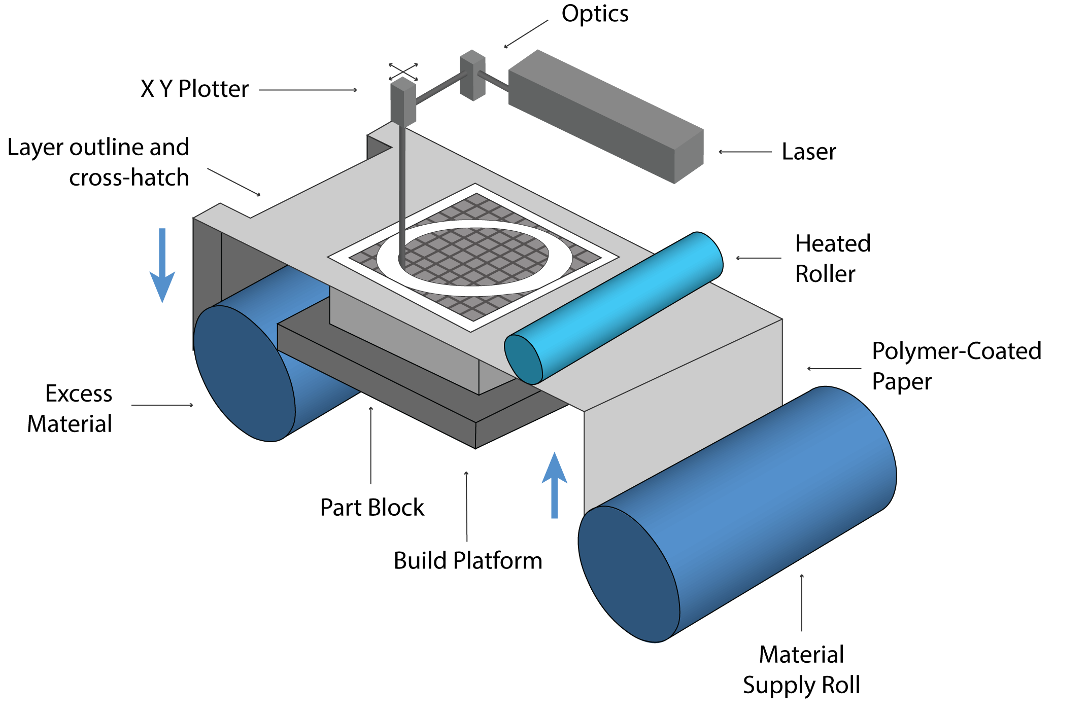
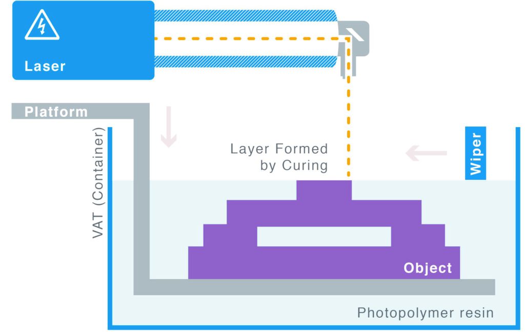
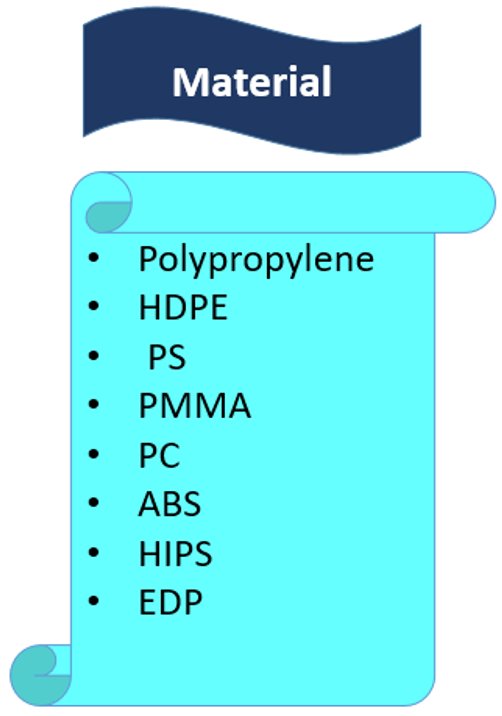
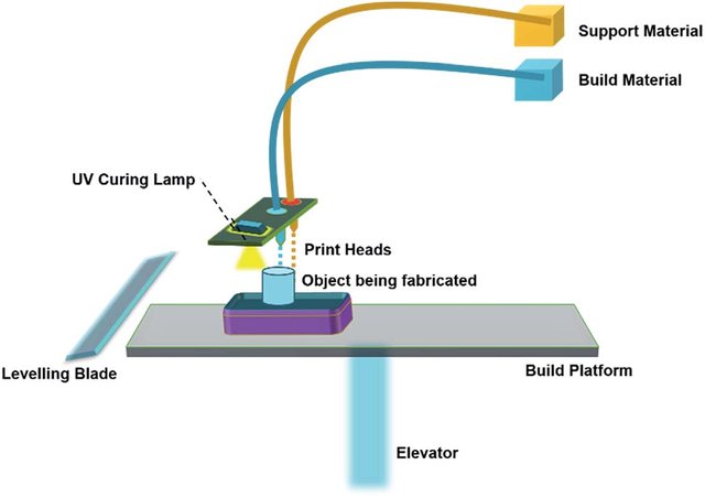
The process of building a three-dimensional object from a CAD model or digital 3D model is known as additive manufacturing or 3D printing. In an additive process, an object is made by adding layers of material one after another until the product is made. This process can be done via several methods in which material is joined, deposited, and solidified under computer control. The materials being added together could be made of plastics, liquids or powder grains being fused, etc. 3D printing Abaqus modeling is fully described in this training package.
Additive manufacturing or 3D printing simulation in ABAQUS
Why do we need to simulate 3D printing in Abaqus? Because of the same reasons, we do other simulations. Checking if there is any residual stress, checking temperature and thermal conditions, deflection in the model, etc. Moreover, to see if the machine’s settings suit our model’s conditions before printing to avoid unnecessary costs. Conditions like material properties, temperature, etc.
This 3D printing Abaqus training package will teach you to do this simulation with two methods: The first method is based on the use of subroutines and Python scripting and was done by a team with the goal of coding all the steps of 3D printing, and the second method uses ADM plug-in developed by Dassault Systemes company to simulate 3D printing process.
Method 1: Using Scripting and Subroutines
In this method, we have three coding files. One is a Python script, and the others are USDFLD and DISP subroutines.
Python script: This script will do everything for us. Creating material properties, sections, interactions, basically anything that must be done in the Abaqus GUI, the code will do it for us. You just need to run the script, enter some inputs, and wait until the simulation is completed. About the modelling, you must create your model in CAD software or the Abaqus itself; then layer the model and save the layers as “igs” files. When you run the script, one of the inputs that you should insert is the directory path of these files.
USDFLD subroutine: With this subroutine, we calculate the elasticity properties because in the 3D printing process, the elasticity is not constant and changes during the process. The formulas used to calculate the elasticity in this tutorial are according to these references: “Rapid Prototyping & Manufacturing, Fundamentals of
Stereolithography“, “Curl Distortion Analysis During
Photopolymerisation of Stereolithography Using Dynamic Finite Element
Method“.
The formulas and equations are explained in the tutorial video completely. Of course, you can apply your own equations and assumptions to calculate the elasticity.
DISP subroutine: The temperature changes during the process will be calculated by the DISP subroutine. The formulas used to calculate the temperature changes are based on our assumptions. You can apply yours based on any references you see fit.
There are two workshops for this method, each using a different version of the python code. The first workshop simulates the 3D printing of gear, and this version of the python code used in this simulation is for uniform models. By uniform model, we mean that all layers must be identical if you layer the model. In this workshop, you have to create just one layer of your model in CAD software or the Abaqus itself and save it as an “igs” file; then, when you run the code, you must enter the directory path of the file and some inputs and wait till the job is completed. (3D printing ABAQUS)
In the second workshop, an industrial shaft will be simulated. There are no differences in the subroutine files except for some of their inputs. The version of the python code used in this simulation is for nonuniform models. This means the layers of the model are different. Therefore, we need to have all the layers as “igs” files. After the script is run, we insert the directory path of these files along with other inputs and wait till the job is completed. In this version of python code, there would be other differences as well, which will be explained in the video.
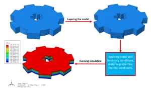
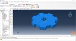
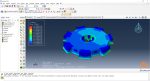
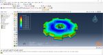
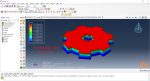
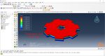
Workshop 1: 3D printing Abaqus simulation of Gear with DISP, USDFLD and Python scripting (Same cross-section)
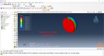
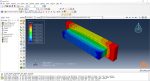
In this workshop, first, the geometry of the model is explained. Next, the difference between continuous and discontinuous layers is discussed, which is an important issue regarding using the Python script for these kinds of examples. Then, material properties with all their equations and detail are explained, and these properties are defined using the USDFLD subroutine. Next, the boundary conditions are explained. After that, the temperature changes and their relations are discussed, which is applied to the model using the DISP subroutine. Finally, after explaining how the Python code and subroutines are written and work, the simulation will be done, and the results will be discussed.
Workshop 2: 3D printing Abaqus simulation of shaft with DISP, USDFLD and Python scripting (non-uniform section)
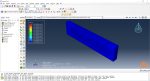
In this workshop, like the previous one, the model’s geometry is explained at first. Next, the model layering is presented. All other stages would be like the previous workshop. The only differences are in the model’s geometry, Python code, and layers; the differences are because this model has a non-uniform cross-section.
Method 2: Using AM Modeler plug-in for additive manufacturing
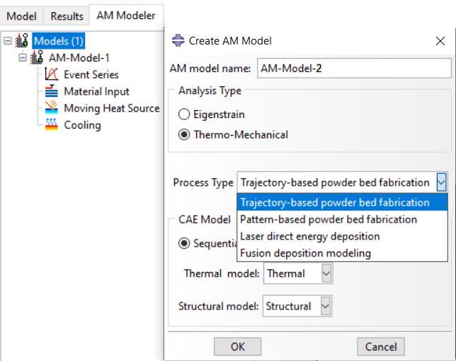
The “AM Modeler” plug-in is a user-friendly interface for additive manufacturing simulation that allows users to simulate 3D printing with minimal risk of errors. Unlike Python scripting or coding, this plug-in only requires users to input the necessary data, create a job, and start the simulation. The plug-in simulates 3D printing using two methods: eigenstrain and thermomechanical. Each method has different process types that users can choose from based on their specific needs. The eigenstrain method has two process types: trajectory-based and pattern-based, while the thermomechanical method has four process types: trajectory-based powder bed fabrication, pattern-based powder bed fabrication, laser direct energy deposition, and fusion deposition modeling. This training package focuses on the thermomechanical method.
The thermomechanical approach involves a thermal-stress analysis of an additive manufacturing process, which is performed sequentially. Initially, a heat transfer analysis is conducted, followed by a static structural analysis that utilizes the temperature fields obtained from the thermal analysis. The simulation allows for precise control over processing conditions in both time and space, resulting in a thorough and realistic solution. However, as time and spatial (mesh) resolution increase, the simulation becomes computationally expensive.
The heat transfer analysis must simulate the progressive material deposition, progressive heating of deposited material, and progressive cooling of the printed part. The stress analysis is driven by temperatures from the heat transfer analysis, and progressive material deposition methods comparable to the heat transfer analysis can be applied. Temperature-dependent material properties can be used for precise stress results.
Workshops of the second method
There are three main workshops for this method: “Sequential thermomechanical analysis of simple cube one-direction LPBF 3D printing using trajectory-based method with AM plug-in”, “3D printing simulation with Fusion deposition modeling and Laser direct energy deposition method with AM plug-in”, and “Material Removing with AM plug-in”. These workshops are done with two versions of the AM Modeler: an older version and a newer version; the first workshop (LPBF) is done with the older version, and the other two with the newer version. Why two versions? It’s because of you to learn how to work with them in case you have each of them.
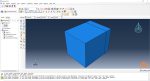
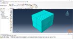
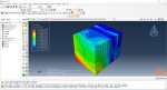
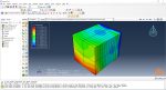
Workshop 3: Sequential thermomechanical analysis of simple cube one-direction LPBF 3D printing using trajectory-based method with AM plug-in
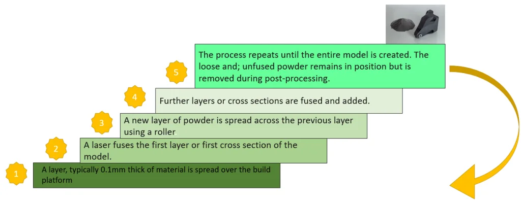
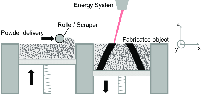
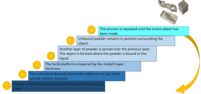
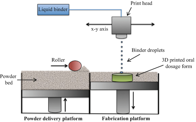
The Laser Powder Bed Fusion (LPBF) method is a 3D printing technique that uses a high-powered laser to melt and fuse metal powders together layer by layer. In Laser Powder Bed Fusion (LPBF), a layer of metal powder is spread over a build platform by a roller. A high-powered laser scans the powder, melting and fusing it together according to the 3D model. The platform is lowered, and the process is repeated layer by layer until the object is complete.
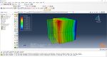
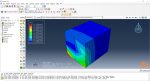
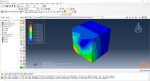
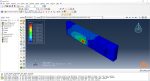
In this workshop, first, the geometry of the model and details of the layers are discussed. After presenting the required material properties, the information and required inputs of the roller and laser beam are introduced, which include their speeds and “Event series” data. Next, the boundary conditions are explained, and then, the modeling in the Abaqus begins. First, the modeling with the Abaqus/CAE is done; then, the inputs required for this simulation, like “Event series” data, will be added via AM Modeler plug-in. Two analyses must be done; first, the thermal analysis, then the structural analysis. In the end, the results will be discussed. This simulation is done using the older version of the AM Modeler plug-in.
You can get Access only to this workshop if you want through this package:
3D printing simulation with Laser Powder Bed Fusion (LPBF) method in Abaqus
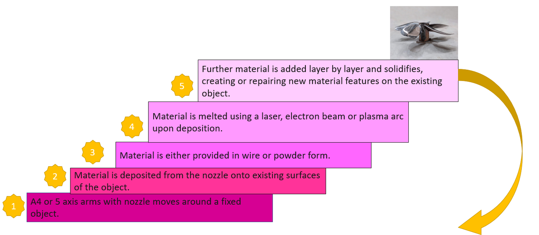
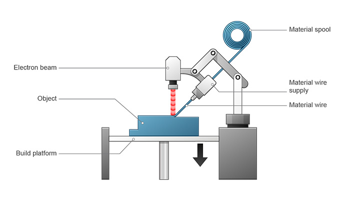
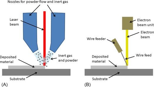
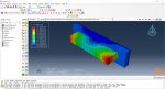
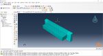
Workshop 4: 3D printing simulation with Fusion deposition modeling (FDM) and Laser direct energy deposition (LDED) method with AM plug-in
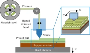
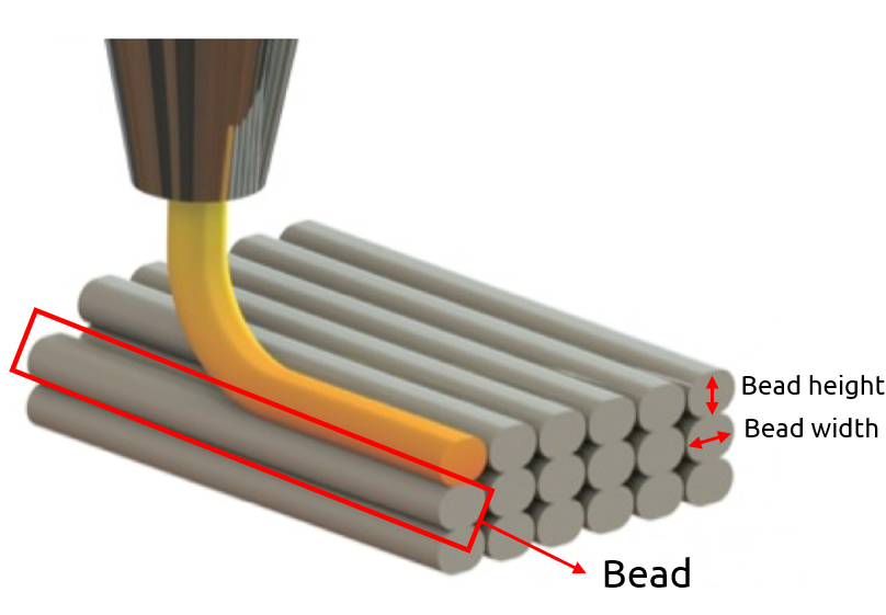
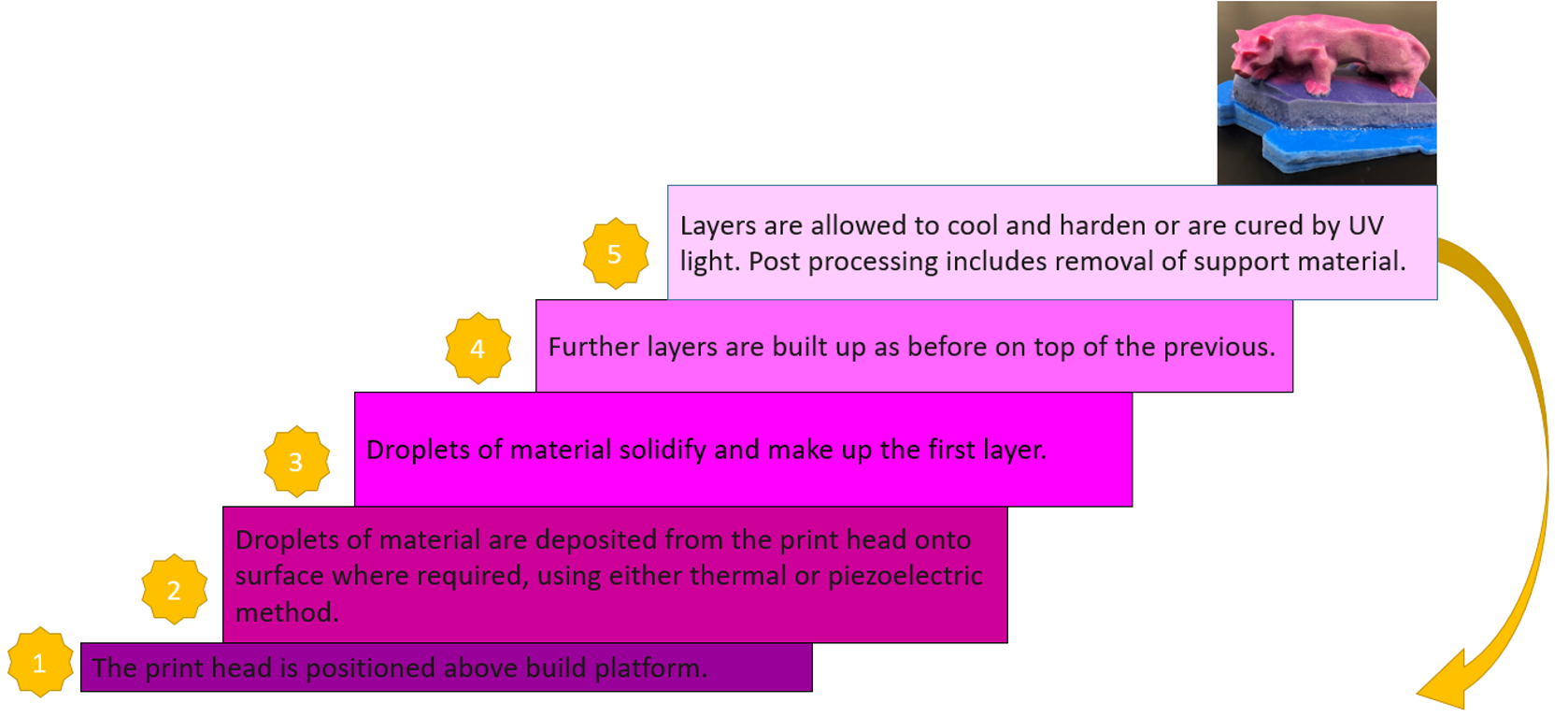
The Fused Deposition Modeling (FDM) method is a 3D printing technique that extrudes melted filament layer by layer to create a 3D object. In this method, a filament is fed into a heated extruder (nozzle), which melts the filament and deposits it layer by layer onto a build platform according to the 3D model. The material cools and solidifies, creating the final object.
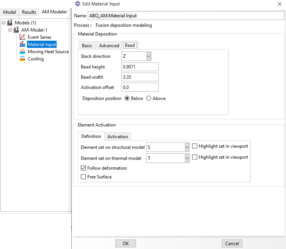
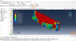
In this workshop, after presenting the model’s geometry, the layering of the model and its details, such as the dimensions of the bead, are explained. Next, the material properties are introduced. After that, the nozzle’s data, such as speed, are represented. All the simulation steps are like the previous workshop except the AM Modeler part because this workshop uses the newer plug-in version.
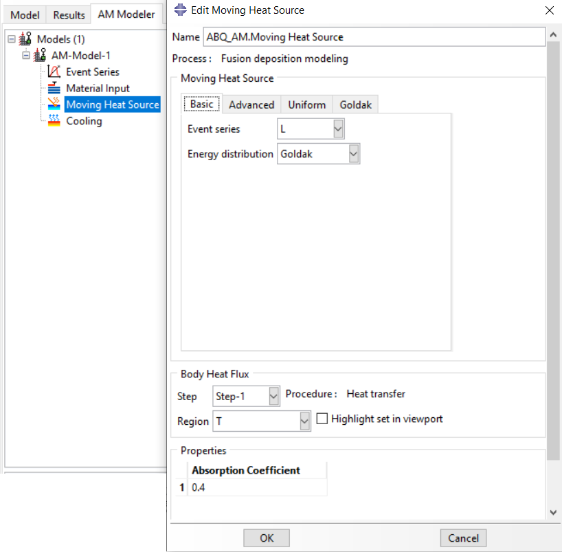
In both workshops, the material is first deposited using the element progressive activation technique (Material Deposition) and heated using a moving heat source. Both material deposition and moving heat source have several types, which are explained in the workshops.
You can get Access only to this workshop if you want through this package:
3D printing simulation with Fused Deposition Modeling (FDM) in Abaqus
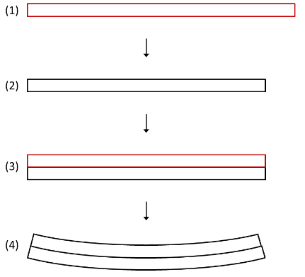
Workshop 5: Material Removing with AM plug-in
This workshop introduces some special-purpose techniques and user subroutines that are available for machining and material removal processes, which often follow an additive manufacturing process. This workshop will teach you how to do a material removal process on a simple cube. This simulation is simply done by defining a bead and an event series along with required special-purpose techniques, “ABQs”. The bead is for assigning the materials that must be removed; the event series is for defining the toolpath trajectory; the ABQs are for applying them and some settings; and the progressive element activation method in a structural or a thermal analysis to deactivates the elements. To do this simulation, after the required settings are done using the AM Modeler plug-in, the input file must be generated, and then, some changes in the input file must be made manually and run the input file.
It would be useful to see Abaqus Documentation to understand how it would be hard to start an Abaqus simulation without any Abaqus tutorial.

kyungmi –
Hi, How does the ADM plugin in the second method handle non-linear material behavior, such as plastic deformation? Can it accurately model complex geometries?