

All about composite analysis | Composite simulation
Composites Abaqus | Abaqus composite is fully discussed in this post. See the content at a glance: In this Abaqus composite tutorial, we will first briefly introduce composite materials.(Abaqus composite material): Second, we will learn the role of composite materials in the world and understand why we need them. Third, we will become aware of the composite material categorization in different aspects. Finally, in what ways and how do we need composite analysis? (analysis of composite)
When you enter the engineering world, one of the first things you will hear is “Composite”. Most likely, you hear it in some of your conversations when you talk about your dental problems, buildings, airplanes, etc.
In this blog, you will learn about composite materials from the beginning to advanced. Many of your questions about these materials will be answered. So, be with us until the end and enjoy learning in the engineering world.
Read More: abaqus tutorial + 100 abaqus courses
1. What is a composite?
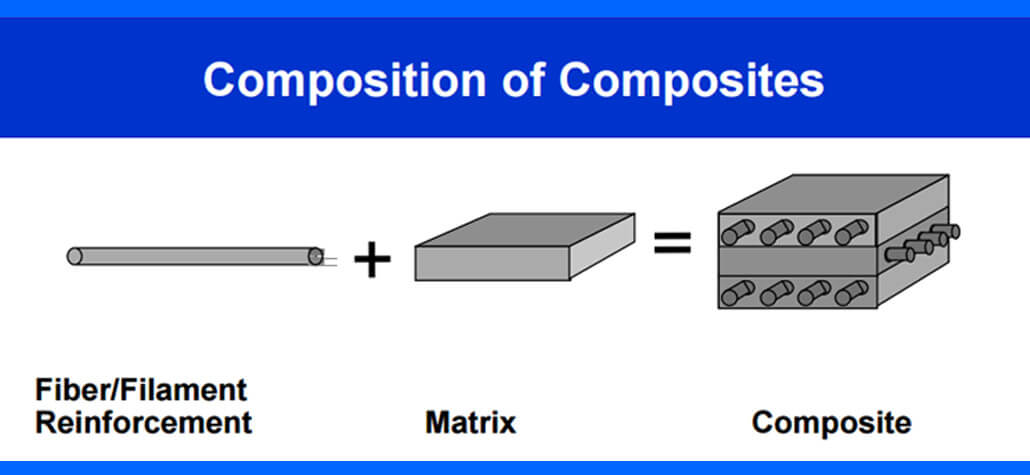
In the beginning, I’d like to define the word “composite” in a very simple sentence: Two different materials that just lock together and they’re not dissolved, creating a new material that has properties we need for a specific application.
These two materials have various physical and chemical properties. When they create a composite, the new material will have new properties, unlike the constituent materials. Properties such as becoming stronger, lighter, or electrically resistant.
One of these materials is called “Matrix” which has soft properties compared to the other one. The other material which we could call the “reinforcement” has stiffer and stronger properties compared to the Matrix. The reinforcement part is surrounded by the Matrix, and you may know it as fibers.
Some examples of composite materials
- Human Hair
- Wood
- Bone
- Mud bricks
- Translucent Concrete
- Absorbent concrete
- Fiberglass
- Carbon Fiber
- Kevlar
Now that you know what composite material is, let’s talk about “why we need them?” What are the advantages and disadvantages of these materials?
2. Why do we need composites?
Compared to other common materials, composites are known mostly because of their strength and lightness. Imagine you want to design a plane; you must select a material with properties such as high strength, being as light as possible to fly, and being flexible. Common materials like steel have the strength we need, but they’re heavy and do not have the flexibility we need. Well, the best choice would be composite.
Manufacturers can create qualities that precisely meet the needs of a specific structure for a specific purpose by selecting the right reinforcing and matrix material mix. Take a look at the table below; there are some advantages and disadvantages of these materials.
Some practical examples of composite materials are:
Buildings (e.g., Reinforced concrete with CFRP), bridges, and other constructions, including boat hulls, swimming pool panels, racing car bodies, airplanes, storage tanks, etc. Additionally, they are being employed more and more in standard automotive applications.

Reinforced concrete with CFRP
Moreover, you can see them in your house and kitchen. Bathtubs, shower stalls, replica granite, cultured marble basins, and countertops are frequently made of composite materials.
 |
⭐⭐⭐ Abaqus Course | ⏰10 hours Video 👩🎓+1000 Students ♾️ Lifetime Access
✅ Module by Module Training ✅ Standard/Explicit Analyses Tutorial ✅ Subroutines (UMAT) Training … ✅ Python Scripting Lesson & Examples |
Still with us, right?!
Now, let’s see the composite material classifications.
3. Composite classifications
As we said before, the composites are made of two materials; one is called the “matrix,” and the other is called “reinforcement”. Therefore, the composites can be classified based on two criteria:
- Based on the “matrix” material
- Based on the “reinforcement” material
Each of them will divide into several types. To understand composite analysis, it is important to know these two materials and their role in composite structures.
The first criterion divides into three types: Organic Matrix Composites (OMCs), Metal Matrix Composites (MMCs), and Ceramic Matrix Composites (CMCs).
The second criterion divides into five types: Particle Reinforced Composites, Flake Reinforced Composites, Fiber Reinforced Composites, Structural Composites, and Nanocomposites.
Don’t worry! We’ll explain them all in the simplest way possible with practical examples.
3.1. Based on Matrix material
The composites are classified into three types based on this criterion:
1. Organic Matrix Composites (OMCs): Generally, OMC refers to two types of composites; Carbon matrix composites which you may know of them by the name Carbon-Carbon composites; and Polymer Matrix Composites (PMCs).
- Polymer matrix composites (PMCs) have drawn a lot of attention, largely because they are more affordable and have higher stiffness and specific strength than traditional metallic alloys. Additionally, PMCs provide greater design freedom and better corrosion and fatigue resistance. But, they have some disadvantages and the most important of them are low working temperatures, high coefficients of thermal and moisture expansion, and poor elastic characteristics in some directions. Read More
2. Metal Matrix Composites (MMCs): A composite material called metal matrix composite (MMC) has fibers or particles spread in a metallic matrix made of steel, copper, or aluminum. Usually, a ceramic (such as silicon carbide or alumina ) or another metal (such as steel) makes up the reinforcement phase. Over polymeric matrices, metal matrices have the benefit of being appropriate for usage in applications requiring long-term resistance to harsh conditions. It is true that most metals have higher yield strengths and modulus than polymers. The ability to plastically deform and strengthen metals through numerous heat and mechanical processes is another benefit of using metals. Read More
3. Ceramic Matrix Composites (CMCs): In Ceramic Matrix Composites (CMCs), ceramic materials are used for both matrix and reinforcement parts. Any ceramic material can be used to make the matrix and fibers. For example, the matrix can be made of Calcium aluminosilicate and the reinforcement part can be fibers such as carbon or silicon carbide. The advantages of the CMCs are including applications in extreme service temperatures, chemical inertness, high creep resistance and thermal shock, low density, high fracture toughness compared to conventional ceramics, etc. Read More
I didn’t bore you so far, did I?! Let’s get to the next criterion.
3.2. Based on Reinforced material
We have five types based on this criterion:
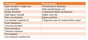
1. Particle Reinforced Composites: Particle-reinforced composites are made up of a matrix that has been strengthened by a dispersed phase made up of particles. Some advantages of this type are including oxidation resistance, these have lower cost and are simpler to produce and construct compared to fiber-reinforced ones, high wear resistance, etc. This one divides into two levels; large particle composites like concrete and dispersion-strengthened composites. Some common examples of this type are:
-
- Concrete
- Particle board
- Road surfaces
Schematic of Particle Reinforced composite [Ref]
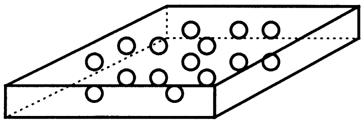
2. Flake Reinforced Composites: This type consists of flat reinforcements of matrices. High out-of-plane flexural modulus, increased strength, and the inexpensive price is a few benefits of this type. However, flakes can’t be easily orientated and there aren’t many materials that can be used. Glass, mica, aluminum, and silver are examples of common flake materials.
Schematic of Flake Reinforced composite [Ref]
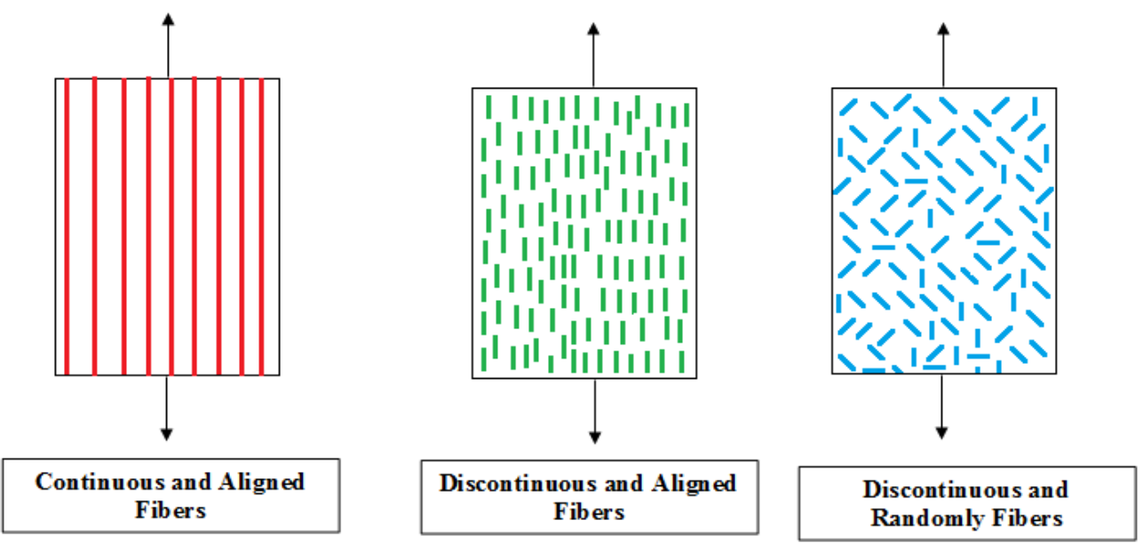
3. Fiber Reinforced Composites: This type consists of matrices reinforced by fibers. Just take a look at the figure below to get an idea of what is the fiber-reinforced composite.
Schematic of Fiber Reinforced Composite [Ref]
Regarding the size of the fiber, fiber-reinforced composites are divided into two categories: continuous and discontinuous. When referring to fibers that are as long as the composite material, the phrase “continuous-fiber-reinforced composite” is used, whereas “discontinuous-fiber-reinforced composite” is used to describe fibers that are relatively short in contrast to the size of the composite material. The fibers could be distributed aligned or at random in the discontinuous type. See the figures below to understand better. Composite simulation
The continuous type could be aligned unidirectional, bidirectional, or even woven.
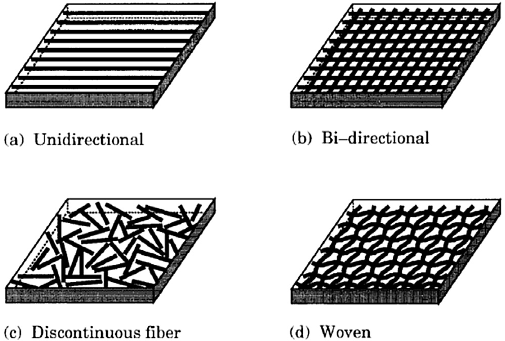
Different types of fiber-reinforced composites [Ref]
I know you might get confused with all these categories. But take a deep breath and look at the pictures again. The pictures always help to better understand something.
Now, it’s time to see some practical examples of Fiber-Reinforced Composites (FRCs):
Glass Fiber Reinforced Polymer (GFRP), Carbon Fiber Reinforced Polymer (CFRP), etc. The most common CFRP composite productions are Tennis rackets, golf clubs, softball bats, hockey sticks, and archery arrows and bows. Some applications of GFRP are in Electronic enclosures, Water pipes or drain coverings, and Sporting equipment such as kayaks, Helicopter rotor blades, wind turbine blades, etc.
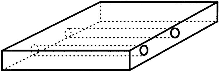
4. Structural Composites: This type comes into two models; Laminar composites and Sandwich composites.
An assembly of fibrous composite material layers that can be linked to provide the necessary technical qualities, such as in-plane stiffness, bending stiffness, strength, and coefficient of thermal expansion, is known as a composite laminate. Each layer may comprise unidirectional continuous fibers, short fibers, or braided or woven fibers embedded in a matrix. Depending on the projected loading of the structure where the laminate will be utilized, the plies are laid out differently.
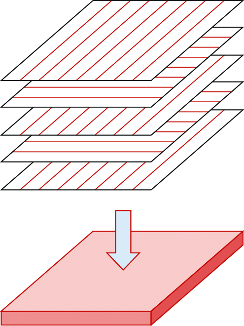
Composite laminate [Ref] |
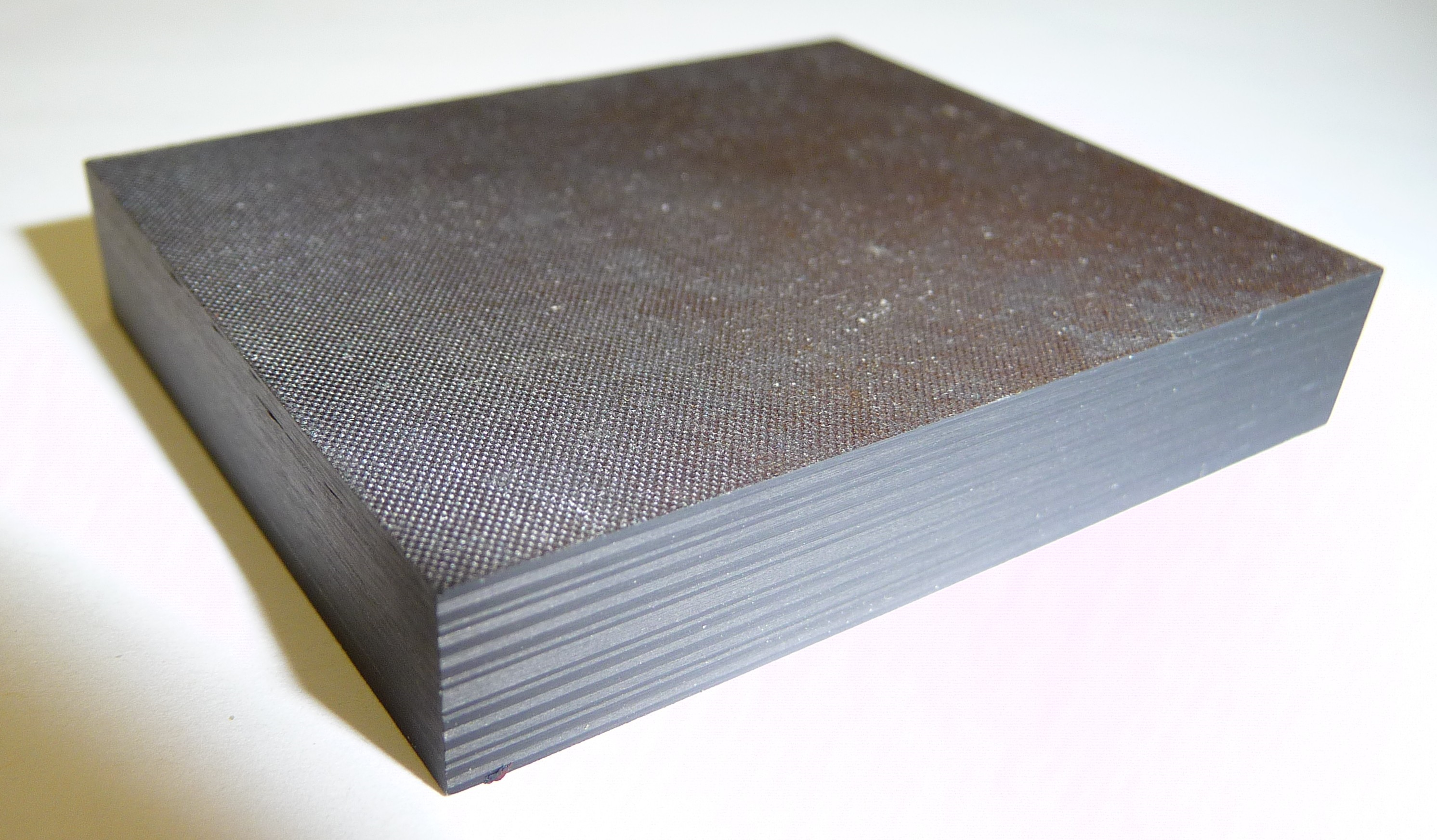
composite laminate specimen |
Sandwich plates are made up of a core covered by facesheets. Due to their high bending stiffness-to-weight ratio, sandwich plates are widely utilized in place of solid plates. The distance between the load-bearing facesheets causes the high bending stiffness; and the core’s lightweight causes the structure lightweight. Each facesheet must be thin in comparison to the core, whether it be an isotropic material or a fiber-reinforced composite laminate. Foam or honeycomb may be used for the core, which must have a material symmetry plane parallel to its midplane and have less in-plane stiffness than the facesheets.
|
|
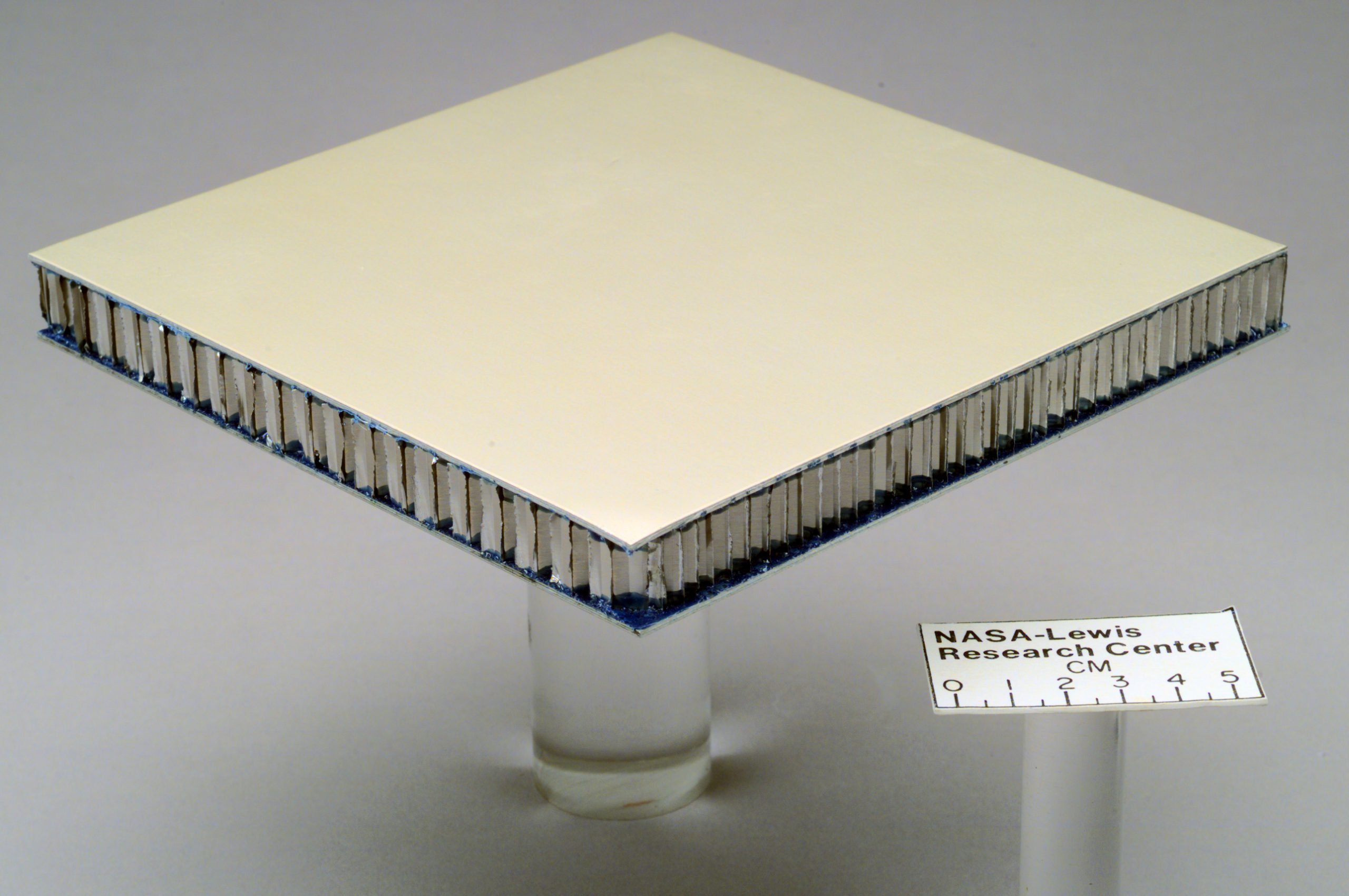 |
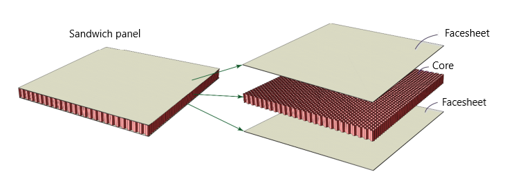
Sandwich composite
I hope you are not bored yet! But don’t worry, we’re going to tell you the final type.
5. Nanocomposites: Materials of the scale of nanometers make up nanocomposites (10–9 m). A constituent must be less than 100 nm in order for something to be considered a nanocomposite. Materials’ characteristics at this size differ from those of the bulk material.
Advanced composite materials typically have microscale components (10–6 m). The majority of the qualities of the resulting composite material are superior to those at the microscale, thanks to the use of nanoscale components. However, some nanocomposites’ qualities, like toughness and impact strength, can actually worsen.
Nanocomposite films have improved qualities including elastic modulus and transmission rates for water vapor, heat distortion, and oxygen in packaging applications for the military, among other uses.
As there are many types of composites, Composites Abaqus analysis can help us choose the best type for a specific application. Let’s take a look at composite analysis to better understand this process.

4. Composite Analysis | Composite simulation
Analysis of Composite (composite simulation) is necessary for designers to ensure that composite structures are strong and stiff enough while minimizing weight. One useful method for composite analysis under loads is Classical Laminate Analysis (CLA). This theory is used to predict the strains, displacements, and curvature that emerge in a composite when it is exposed to mechanical and thermal loads. In other words, CLT can be used to analyze the behavior of composites with multiple plies. It can even be applied to composites that have a core in the middle. Composite Analysis and Abaqus composite simulation are fully discussed in this post.
Performing CLA manually can be challenging due to recurring computations and complex matrices. To simplify the process, Finite Element Analysis (FEA) software like Abaqus can be used. There are some differences between FEA for metal and composite in Abaqus. The element property card is different because the properties of each ply depend on its orientation.
All we have to do is to input Mechanical parameters like E1, E2, etc., for each lamina, followed by the desired stacking sequence.
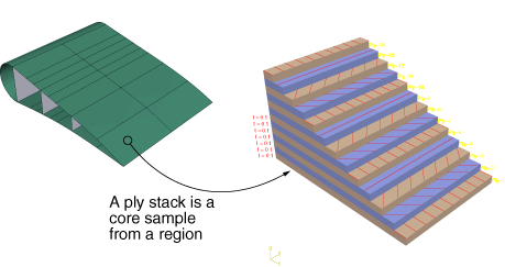
composite simulation a ply stack plot [Ref]
Overall, using composite analysis and methods like CLA and FEA can help designers create strong, lightweight composite structures. (composite simulation)
After obtaining the stress and strains in composite materials (doing stress composite analysis), we usually have to study the composite damages to prevent failure in these materials. The following explanations provide information on this subject.
4.1. composite damage analysis
In comparison to metals, composites’ damage mechanisms are less well known. Composite materials and structures are susceptible to defects, whether they appear during material processing, component fabrication, or in-service use. Understanding how the damage or defect affects the structural integrity of the composite component is crucial to determining how critical the defect is. If we can somehow determine these damages and tend to them in time, the maintenance cost would be severely decreased. Also, our design will be better and well-optimized.
The composite damages can be classified into two levels:
4.1.1. Composite damage during manufacturing
Anomalies caused by processing errors like porosity, microcracking, and delaminations are examples of manufacturing damage. Inadvertent edge cuts, scratches, surface gouges, impact damage, and damaged fastener holes are also included. Manufacturing flaws consist of:
- Voids
- Air bubbles
- Delamination
- Resin starved areas
- Resin rich areas
- Wrinkles
- …
Porosity, or the existence of a void in the matrix, is the most typical one. Incorrect or ineffective curing parameters may be to blame for the porosity. Another production flaw is the inclusion of foreign bodies in the matrix, which can be anything from greasy fingerprints to a backing film.
4.1.2. In-service damage of composites
It’s true that the composite structures have sufficient strength and stiffness but like other structures, they may get damaged during the service. The damages could be caused by impact, low resistance to the service environment, overloading, Staff carelessness, etc.
In-service damages include:
- Impact damage
- Fatigue
- Cracks
- Delamination
- Fiber fracturing
- …
Service flaws in composite structures are typically caused by impact damages. Delamination is the most frequent impact-related damage. Delamination occurs when layers in a laminated composite are split, creating a mica-like structure with a considerable loss in mechanical properties. Delamination is the separation of the laminate at the boundary between two layers as a result of shock, impact, or repeated cyclic pressures. Individual fibers can pull away from the matrix, for instance.
Analysis of composites and determining the defects and damages so that the structure can keep working properly and lower the cost of maintenance is the engineer’s duty. With the help of Computer-aided engineering (CAE) and the finite element method (FEM), the composite analysis is done in the best way possible. Composite simulation is a special skill that can be achieved by our training packages.
We are here at the CAE Assistant to explain some about composite material damage and introduce some FEM tools to simulate these damages correctly. Also, we will help you learn how to simulate and analyze your model and structure. With our high-quality education, you can learn how to work with Abaqus composite materials and perform accurate composite analysis.(Composite in Abaqus)
|
⭐⭐⭐ Abaqus Course | ⏰10 hours Video 👩🎓+1000 Students ♾️ Lifetime Access
✅ Module by Module Training ✅ Standard/Explicit Analyses Tutorial ✅ Subroutines (UMAT) Training … ✅ Python Scripting Lesson & Examples |
4.2. Types of damage in composites
Here are some of the most common types of damage that can occur in composites:
Matrix Damage:
- Matrix Cracking: This occurs when the resin holding the fibers together cracks under stress. It can be caused by impact, fatigue, or thermal cycling.
- Fiber-Matrix Debonding: This happens when the bond between the fibers and the resin weakens or breaks. It can be caused by manufacturing defects, chemical exposure, or mechanical stress.
Fiber damage:
- Fiber Breakage: This occurs when the fibers themselves break under stress. It can be caused by impact, fatigue, or overloading.
Interfacial damage:
- Delamination: This is the separation of two or more layers of the composite. It can be caused by impact, fatigue, or moisture absorption.
Other damage:
- Porosity: This is the presence of air pockets in the composite. It can weaken the material and make it more susceptible to other types of damage.
- Moisture Absorption: Composites can absorb moisture, which can lead to swelling, warping, and loss of strength.
- Chemical Exposure: Some chemicals can degrade the resin or fibers in a composite, leading to loss of strength and other problems.
- Ultraviolet (UV) Radiation: UV radiation can damage the resin in a composite, leading to cracking and loss of strength.
The type of damage that is most likely to occur in a composite depends on a number of factors, including the type of composite, the way it is manufactured, and the way it is used. It is important to be aware of the different types of damage that can occur in composites so that you can take steps to prevent them or detect them early.
4.3. Factors influencing damage in composite materials
The damage susceptibility and severity in composite materials can be influenced by a wide range of factors, broadly categorized into:
Material factors:
- Fiber type and properties: Different fibers (e.g., carbon, glass, aramid) have varying strengths, stiffnesses, and fracture toughness, impacting damage resistance.
- Matrix type and properties: Resins differ in toughness, adhesion to fibers, and environmental resistance, influencing damage initiation and propagation.
- Fiber-matrix interface: Strong bonding between fibers and resin is crucial for stress transfer and resisting delamination.
- Microstructure and defects: Imperfections like voids, porosity, and resin-rich areas act as stress concentrators, promoting damage initiation.
Manufacturing factors:
- Processing parameters: Cure temperature, pressure, and time greatly influence fiber alignment, void content, and matrix properties, affecting damage resistance.
- Surface quality: Poor surface finish can act as initiation sites for cracks and delamination.
- Presence of impurities: Contaminants can weaken the bond between fibers and matrix, promoting debonding and matrix cracking.
Loading and environmental factors:
- Type of loading: Static, dynamic, fatigue, and impact loads affect damage mechanisms and severity differently.
- Magnitude and duration of loading: Higher loads and longer durations increase the risk of damage initiation and propagation.
- Temperature: Elevated temperatures can soften the matrix, weaken the bond, and accelerate damage mechanisms.
- Moisture absorption: Water ingress can plasticize the matrix, reduce strength, and trigger internal stresses leading to damage.
- Chemical exposure: Exposure to aggressive chemicals can degrade the matrix or fibers, causing localized damage and strength reduction.
Design factors:
- Geometry and thickness: Sharp corners, thin sections, and complex geometries concentrate stress, increasing damage susceptibility.
- Fiber orientation: The arrangement of fibers within the composite influences the direction and resistance to specific types of damage.
- Presence of holes and fasteners: Stress concentrations around holes and fasteners can promote damage initiation and propagation.
Understanding these factors and their interactions is crucial in selecting appropriate composite materials, optimizing manufacturing processes, and designing structures with good damage resistance for specific applications. Additionally, ongoing research explores innovative materials and design solutions to further enhance the damage tolerance of composite materials.
4.4 Choosing the Right Tool for Your Composite Design
Modeling composite parts requires specialized software that can handle the unique properties and complexities of these materials. Here’s a breakdown of key factors to consider when selecting the right software:
- Functionality: Does the software offer dedicated tools for composite modeling? Look for features like ply definition, layup creation, and material libraries with common composite options.
- Geometry Complexity: How intricate is your part? Some programs excel at simple geometries, while others handle highly complex shapes efficiently.
- Analysis Needs: Will you be simulating the part’s performance under stress? Choose software with built-in Finite Element Analysis (FEA) capabilities or compatibility with dedicated FEA programs.
- Integration: Does the software seamlessly integrate with your existing CAD workflow? Compatibility with other design tools can streamline the process.
- Cost and User-Friendliness: Consider your budget and team’s skill level. While powerful programs offer extensive features, they might require specialized training.
Popular Professional Composite Design Software:
- ABAQUS: Industry-standard FEA software with robust composite modeling capabilities. Ideal for complex simulations but requires expertise.
- ANSYS: Another powerful FEA suite featuring composite material libraries and analysis tools. Suitable for advanced users.
- Siemens NX: A comprehensive CAD platform with a dedicated “NX Composites” module for defining layups, materials, and analyzing performance.
- Dassault Systèmes Abaqus Composite Design (ACD): Streamlined software specifically for composite design within the Dassault Systèmes 3DEXPERIENCE platform.
Simulation Considerations:
For simulating composite behavior under load, FEA capabilities are crucial. Both ABAQUS and ANSYS offer top-tier simulation tools. However, dedicated composite design software like NX Composites and ACD often integrate seamlessly with their own simulation modules, simplifying the workflow.
Ultimately, the best software depends on your specific needs and project complexity. Consider demos, trials, and user reviews to find the program that best suits your requirements and expertise.
5. Abaqus composite modeling
Until now, you’ve learned so much about composite materials in this Abaqus composite tutorial. You’ve learned “What is a composite material?”, “why we need them?”, advantages and disadvantages of composites, classification of composites, and composite analysis. Now, we’re ready to talk about how to model and analyze these magnificent structures in the Abaqus software. Composite Analysis and Abaqus composite
- First, we talk about how to model a composite in Abaqus, how to create parts, apply material properties, etc.
- Second, we talk about how to simulate damage in composites, damage initiation point, progressive damage, and the most important damage theories such as the HASHIN criterion, Tsai-Wu, Tsai-Hill, Puck criterion, etc.
- Third, fatigue in composites. (fatigue composite)
- And finally, we’ll see some practical examples and simulations of composite in Abaqus (composite simulation).
If you’re interested as we do and want to learn how to do your projects about composite analysis with the FEM method, let’s get right to it and see how to model composite in Abaqus.
5.1. Modeling
As we said, the first step for composite analysis is to model the composite in Abaqus. But you need to know something first. When you want to understand and analyze a complicated material like composites, you look at it from different angles and try to figure out the structure of the model; but what if you check the structure in different scales? Wouldn’t be better?
The understanding of complicated materials utilized in engineering practice can benefit from multi-scale models. in three scales, you can model and start the analysis of the composite structure (Composite Analysis): Macro (100m), Meso (10-3m), and Microscale (10-6m). Look at the picture below to understand better.
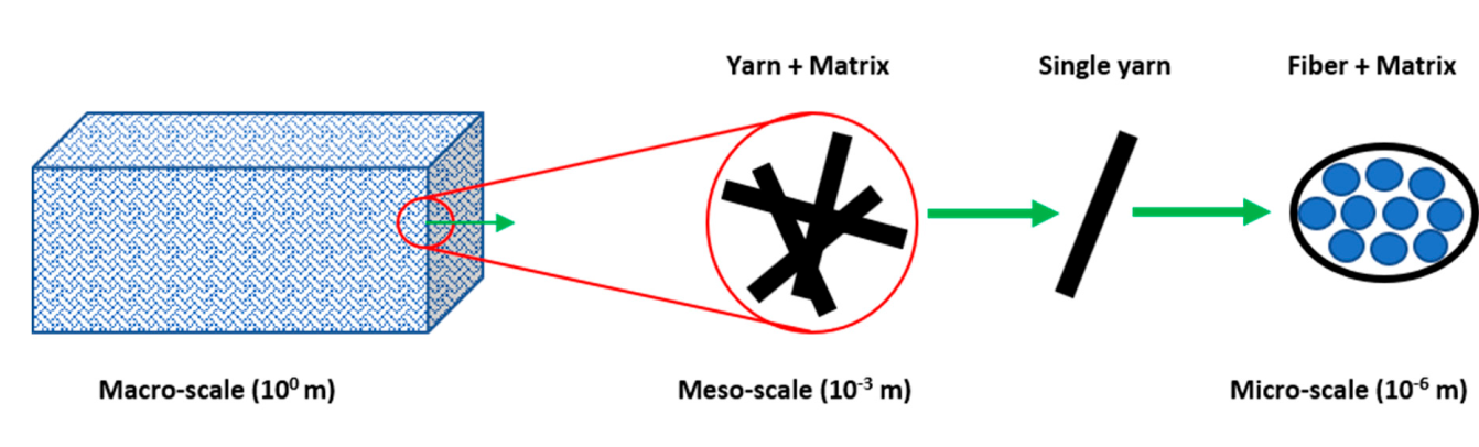
Composite in different scales
Micro-scale (10-6m): RVE analysis is a common method for micro modeling. In composite materials, Representative Volume Element (RVE) is the smallest volume in the structure, which represents the values and properties of the whole model. Each measurement that is made on this volume will yield a value that can be representative of the whole model.
Macro-scale (100m): In macro modeling, instead of separately modeling the components of the composite, the results of the laboratory, as well as the existing theories, suggest that the properties of the composite are introduced to the ABAQUS software in various ways. (common Abaqus composite modeling).
Now, depending on your model and project, you need to choose a scale and start modeling your composite material. Don’t know how and where to start?! Don’t worry! We are here to help you. To start, read Composite simulation| composite analysis (lesson 5).
Need to know more? Check this out:
| You can learn composite modeling and composite analysis with the mentioned methods in this Abaqus composite tutorial. Also, you learn how to model a woven composite in the Abaqus. This training package provides comprehensive basic information and examples of composite modeling in ABAQUS FEM software. |  |
5.2. Composite Damage
Like any structure, composites take damage as well due to the manufacturing process or in-service. Composite material behavior is different compared to other common materials. It has bilinear behavior; just take a look at the stress-strain diagram in the figure below to better understand. When a composite material is subjected to a loading condition that passes the elastic area, it reaches the “damage initiation” point; if the loading condition continues, the damage will propagate, and we have the “progressive damage” area, and the damage might propagate till the composite fails. To run a correct composite analysis, it is crucial to know all composite damage types and their effects on composite materials.
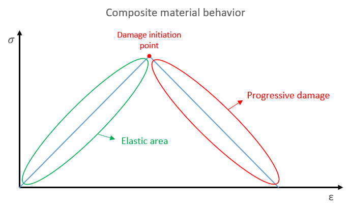
Stress-strain curve for composite materials
In the Abaqus, we must define the “damage initiation” point and the “progressive damage” area; to do so, there are different theories that come in. These theories are categorized into two types: Stress-based and Strain-based.
5.2.1. Abaqus criteria
Like any material, composites are susceptible to damage under various loading conditions. Predicting this damage is crucial for ensuring the lifespan and performance of composite structures. This is where failure criteria come in.
Essentially, failure criteria are like thresholds of stress or strain that, when exceeded, indicate the onset of damage in a composite. By incorporating these criteria into numerical simulations, engineers can identify potential weak spots and predict how the material will behave under specific loads. Composite simulation
You can learn about most common failure criteria used in Abaqus via this link:
The Abaqus capabilities of modeling the damage and progressive damage based on different criteria in the GUI limit only to shell elements.
HASHIN criterion:
In the below package, all available criteria on Abaqus about composites are introduced, and there are some workshops that teach you how to model correctly in Abaqus. Both stress-based and strain-based theories are presented in this package.
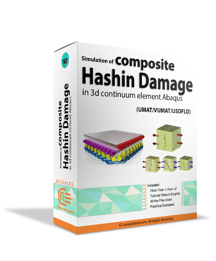
5.2.2. HASHIN criterion for 3D elements
There are different criteria for damage initiation as well as how to reduce the mechanical properties. Three-dimensional HASHIN damage, which involves detecting damage to fibers, matrix, and delamination, is very common. It should be mentioned that progressive damage can be done by reducing the properties suddenly or gradually with different energy methods or equations. Composite Analysis and Abaqus composite simulation.
 |
 |
5.2.3. TSAI criterion for 3D elements
There are also some tutorial packages in this field that will be available on the CAE assistant shop soon.
5.2.4. Puck criterion
There are also some tutorial packages in this field that will be available on the CAE assistant shop soon.
5.2.5. Hybrid composite
There are also some tutorial packages in this field that will be available on the CAE assistant shop soon.
5.3. Composite fatigue
The primary failure mechanism for structures subject to cyclic loading is fatigue. Abaqus is a software that offers various fatigue criteria to predict the fatigue life of materials and structures under cyclic loading conditions. There are several commonly used fatigue criteria supported by Abaqus, including the Stress-Life (S-N) Curve, Strain-Life (ε-N) Curve, Fatigue Damage, Critical Plane Analysis, and Energy-Based Criteria. The Stress-Life Curve is typically used for metallic materials, while the Strain-Life Curve is used for composite materials.
Several factors can affect the fatigue behavior of composite materials, such as loading frequency, stress level, temperature, moisture, and aging. These factors can accelerate or retard the onset of fatigue damage and affect the fatigue life of the composite(fatigue composite)
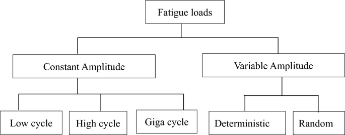
Fatigue loads can be classified based on their amplitude, which can be constant or variable. Here’s a brief overview of each:
- Constant Amplitude Fatigue Load: This type of fatigue load has a constant stress or strain amplitude throughout the loading cycle. The loading history is repetitive and predictable, and the fatigue life can be estimated using S-N curves or other methods.
- Variable Amplitude Fatigue Load: This type of fatigue load has a varying stress or strain amplitude throughout the loading cycle. The loading history can be random or Deterministic. The fatigue life estimation for variable amplitude fatigue loads is more complex and requires the use of statistical methods such as damage accumulation or Rainflow cycle counting.
You can see the fatigue load classification in the figure below:
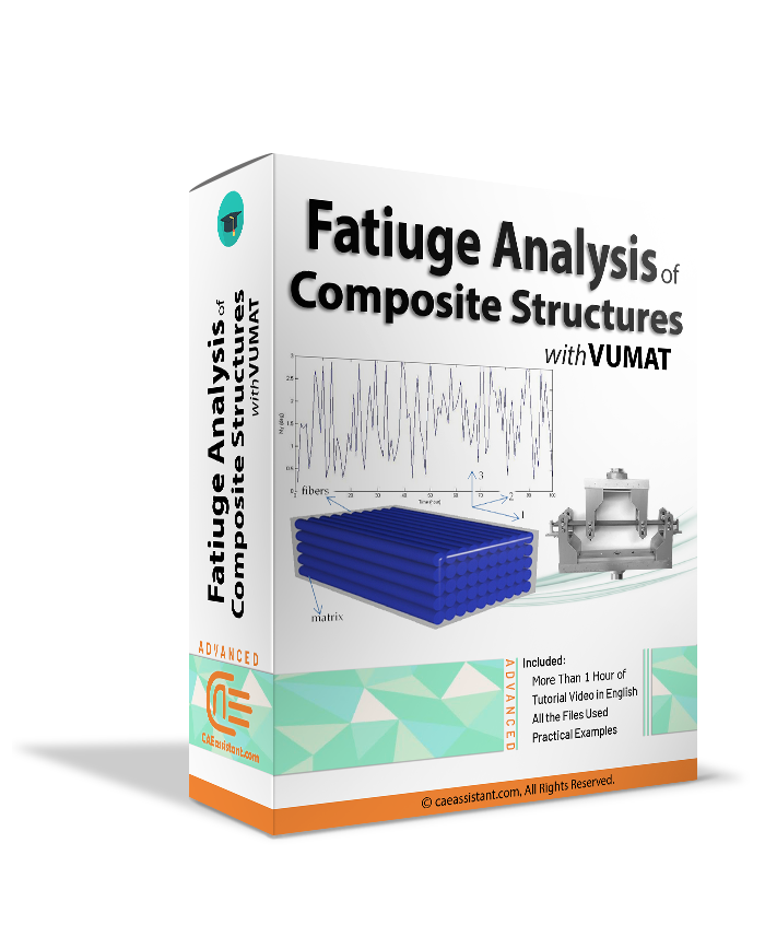
so analysis of composite fatigue(fatigue composite) is very important due to the possible failure costs. Here we have fatigue analysis of unidirectional composites with the UMAT and VUMAT subroutines which use the Shokrieh fatigue theory; Also, there are fatigue analysis of woven composite, short fiber composite, and Balsa wood.
5.3.1. Unidirectional composite
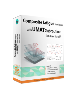 |
 |
5.3.2. Woven composite
| In this training package(composites Abaqus), the modified Hashin fatigue damage model based on the article titled “Life prediction of woven CFRP structure subject to static and fatigue loading “ is used. In this fatigue model, strength and elastic properties reduction and fatigue life are calculated. | 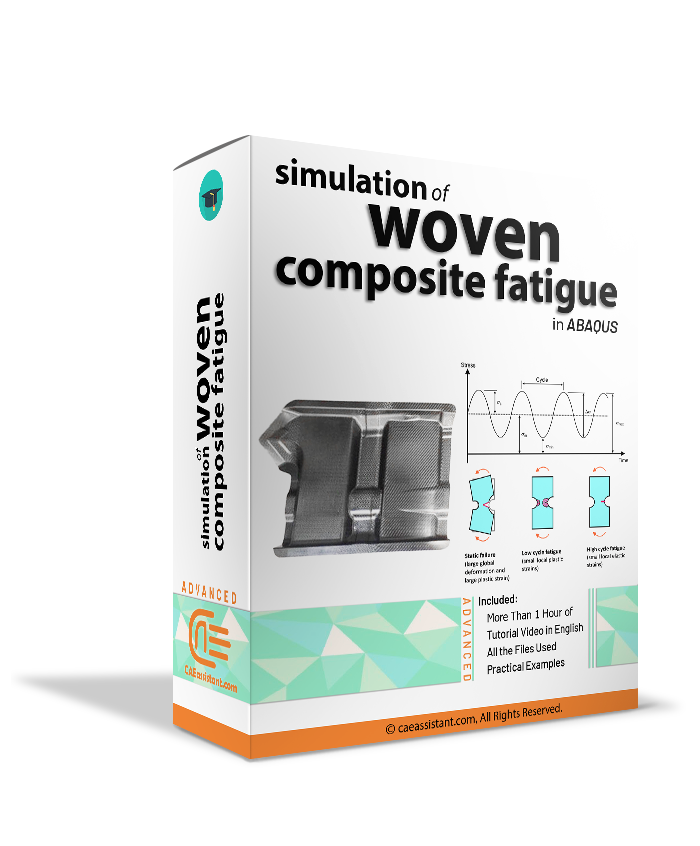 |
5.3.3. Short fiber composite
| The fatigue simulation of short fiber composites with subroutine package is based on “Fatigue behavior and cyclic damage of peek short fiber reinforced composites” article, and the subroutine has been implemented based on the mentioned article. However, this article has used the USDFLD subroutine, but we use the UMAT subroutine in this Abaqus composite tutorial, which is more accurate than USDFLD since the material strength and properties reduction is smooth. | 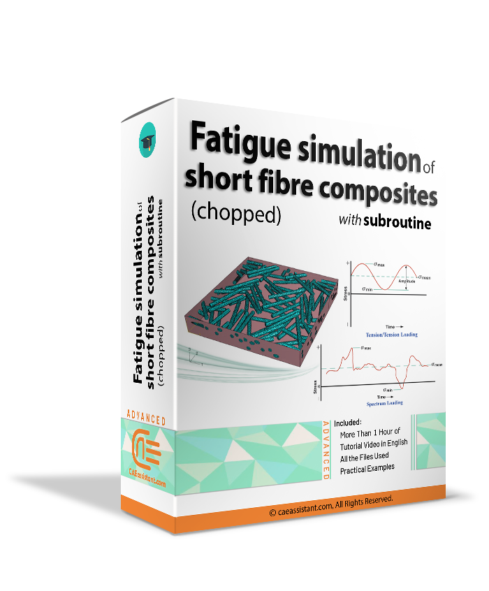 |
5.3.4. Wood
| This training package focuses on writing subroutines to simulate wood fatigue in Abaqus. In the “Balsa wood fatigue simulation with subroutine” package, the used fatigue theory of wood has been described. Then, the flowchart of the subroutine and writing subroutine line-by-line is explained. It helps users to develop the subroutine based on customized theory. Also it can be extended to other Abaqus composite materials with properties close to wood. Finally, the subroutine is implemented on the Abaqus model, and the results are discussed. |  |
5.4. Composite structure
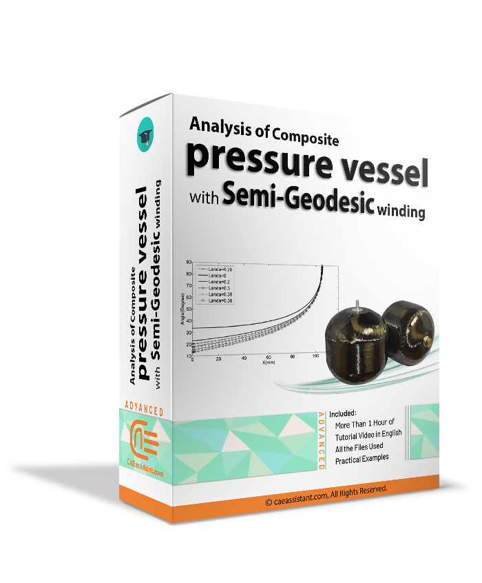
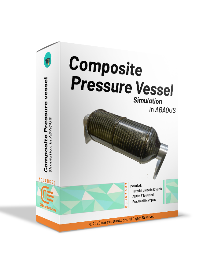
Due to the increasing growth of science and industry, there is a need to develop advanced materials with more profits. Abaqus composite materials, due to their higher efficiency and economic benefits, have become a suitable alternative to traditional materials in various industries. Therefore, the development of these materials by understanding how to produce and study their properties using Abaqus software is essential. The composites are used in many fields such as pressure vessels, aerospace, military, civil structures, etc.
5.4.1. Composite pressure vessel
A composite pressure vessel is a type of pressure vessel made of composite materials, such as carbon fiber reinforced polymer (CFRP), that offers high strength-to-weight ratio and corrosion resistance. The design of a composite pressure vessel involves modeling the composite material behavior under various loading conditions using finite element analysis (FEA) software. The design and analysis of a composite pressure vessel can be successfully performed using Composites Abaqus simulations
 |
 |
| ✅ Subscribed students | +80,000 |
| ✅ Upcoming courses | +300 |
| ✅ Tutorial hours | +300 |
| ✅ Tutorial packages | +100 |
Hello, thank you for this useful article. I learned a lot of good points about the analysis of composite materials.
Do you recommend me any training package for the analysis of chopped composite materials?
thank you