Step by Step Guide to Abaqus DLOAD & VDLOAD Subroutines
In finite element analysis, accurately defining distributed loads is essential for reliable results, and Abaqus offers the DLOAD & VDLOAD subroutines as a tool to achieve this. These subroutines allow users to define custom, spatially, and temporally varying distributed loads, offering flexibility over predefined load types. It is particularly useful for simulating complex conditions, such as wind, wave, or buoyancy forces, where loads change with factors like position, time, or environmental conditions.
The subroutine enables the definition of both concentrated and distributed loads, with the ability to adjust load magnitudes based on parameters like element number and integration point. This makes it ideal for scenarios involving spatially varying pressures, fluid flow, or thermal effects that cannot be captured with standard load types.
While powerful, the DLOAD & VDLOAD subroutines require careful implementation to avoid errors. Users must ensure load definitions align with the model’s specifics to maintain simulation accuracy. In this blog, we will explore the key features of these subroutines, practical applications, and implementation tips. We’ll cover how to use it, discuss its requirements, and provide a step-by-step guide to help users integrate this tool effectively into their simulations, enhancing both precision and reliability in their results.
Do you want to learn DLOAD and VDLOAD subroutines step by step through tutorial videos with 5 Practical examples? 5 Examples!! Of course, you’ll get subroutines files and other files for each example. Just Click Below.
 |
|
1. Understanding the Basics of DLOAD & VDLOAD Subroutines
The DLOAD & VDLOAD subroutines in Abaqus allow users to define complex, user-specified loading conditions during a simulation. Unlike standard loading options in Abaqus, DLOAD provides the flexibility to customize load distributions based on spatial, temporal, or other parameters.
To use the subroutine correctly, it is necessary to understand its main concepts.
The DLOAD & VDLOAD subroutines have different user interfaces. In addition, each subroutine has certain variables which are explained in this section. Some examples are given for better understanding. Here’s a breakdown of how each subroutine works:
1.1. User Subroutine Interface
User DLOAD & VDLOAD subroutine interfaces Fortran code is shown, respectively.
SUBROUTINE DLOAD(F,KSTEP,KINC,TIME,NOEL,NPT,LAYER,KSPT,
1 COORDS,JLTYP,SNAME)
C
INCLUDE 'ABA_PARAM.INC'
C
DIMENSION TIME(2), COORDS (3)
CHARACTER*80 SNAME

user coding to define F

RETURN
END
subroutine vdload (
C Read only (unmodifiable)variables -
     1 nBlock, ndim, stepTime, totalTime,
     2 amplitude, curCoords, velocity, dirCos, jltyp, sname,
C Write only (modifiable) variable -
     1 value )
C
      include 'vaba_param.inc'
C
      dimension curCoords(nBlock,ndim), velocity(nBlock,ndim),
     1  dirCos(nBlock,ndim,ndim), value(nBlock)
      character*80 sname
C

      do 100 km = 1, nBlock
        user coding to define value

  100 continue

      return
      end
1.2. DLOAD Variables
The definitions of variables that are used in the DLOAD subroutine are explained in this section. There are two types of variables, variables to be defined and variables passed in for information.
Before we go further, you probably want to know more about when we need the Abaqus DLOAD and VDLOAD subroutines. well, we have answered that question completely in the introduction of our tutorial: “When do we need to use the subroutine?“
 |
⭐⭐⭐ Free Abaqus Course | ⏰10 hours Video 👩🎓+1000 Students ♾️ Lifetime Access
✅ Module by Module Training ✅ Standard/Explicit Analyses Tutorial ✅ Subroutines (UMAT) Training … ✅ Python Scripting Lesson & Examples |
1.2.1. Variables to be defined
- F
The magnitude of the distributed load, which would be a function of time, displacement, etc.
1.2.2. Variables passed for information
1. KSTEP
The KSTEP parameter represents the current analysis step number during the simulation. It is an integer value It is an integer value that indicates which step of the analysis is being processed during simulation.
2. KINC
The KINC parameter provides the increment number. It is an integer value that provides the increment count during the simulation.
3. TIME (1)
The TIME (1) parameter displays the current value of the current step time or the current value of the load proportionality factor. It is a real number.
4. TIME (2)
The Current value of total time from the beginning of the analysis.
Let’s know more about the step, increment, and step time:
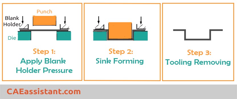
The step refers to the analytical procedure you define to solve the problem. This may consist of a single step or multiple steps. For instance, consider this forming process illustrated in Figure 1, which comprises three distinct steps.
Figure 1: Three steps of forming process
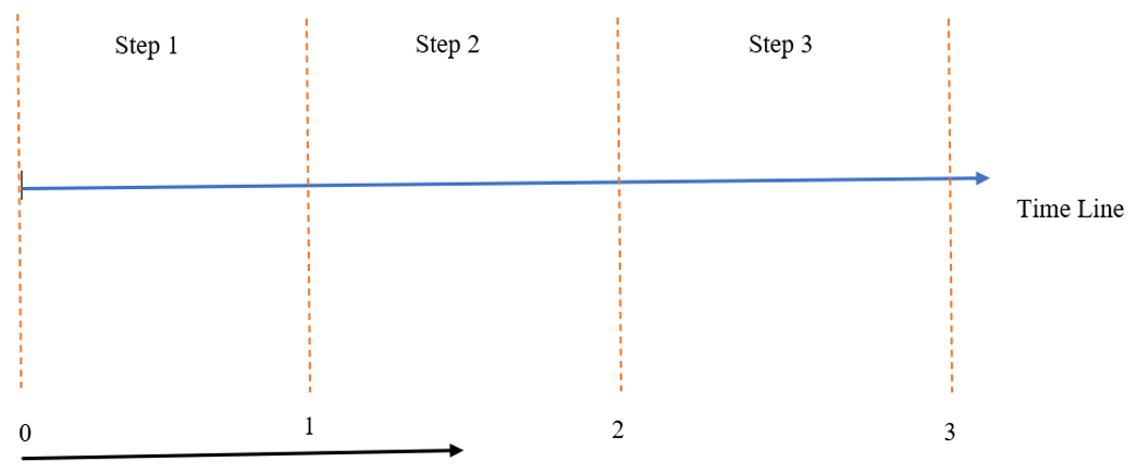
Imagine this is the timeline of the forming process which contains three steps as Figure 2.
Figure 2: Schematics of timeline and steps
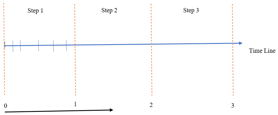
Each step can be broken into smaller parts which are called increments. In the Figure 3, the first step is divided into 6 increments. The number of increments can be variable in each step which can be specified by ourselves or automatically.
Figure 3: Increments of step
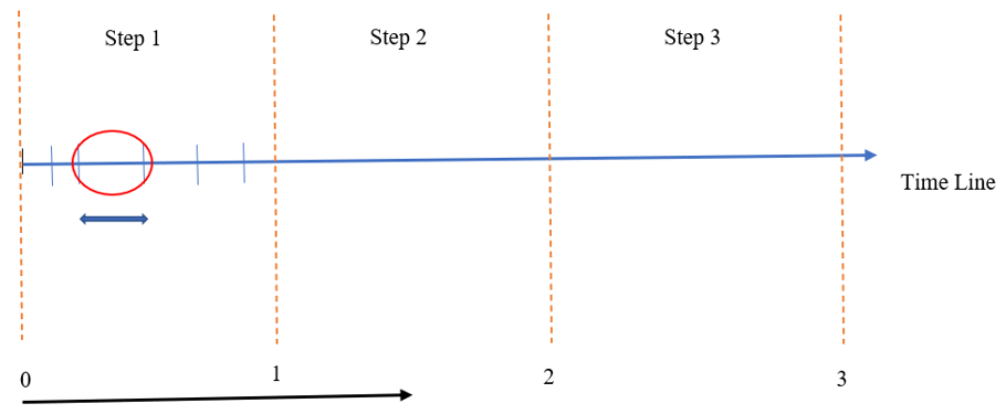
The distance between every two increments is the increment size as shown in Figure 4.
Figure 4: Increment size
5. NOEL
The NOEL parameter represents the element number. Specifically, NOEL is an integer that uniquely identifies an element in the model. It can be used to apply loads or other boundary conditions to specific elements within the finite element model.
6. NPT
The NPT parameter provides load integration point number within the element or on the element’s surface, depending on the load type.
7. LAYER
The LAYER parameter is used to specify the layer number (for body forces in layered solids).
8. KSPT
The KSPT parameter is an integer that represents the section point number within the current layer.
9. COORDS
The COORDS parameter refers to an array representing the coordinates of the load integration point. If geometric nonlinearity is considered during the step, the array reflects the current coordinates. Otherwise, it contains the point’s original coordinates. For axisymmetric elements permitting non-axisymmetric deformation, COORDS (3) specifies the angular position of the integration point in degrees.
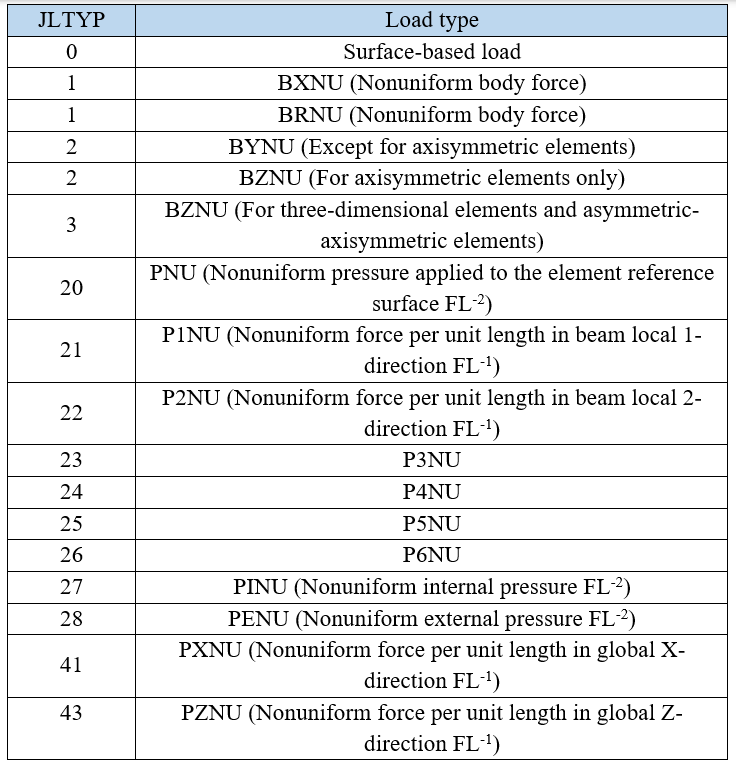
10. JLTYP
Determines the type of load for which DLOAD is being called. The load type can be categorized as a body force, a surface-based load, or an element-based surface load. This information is helpful when multiple unevenly distributed loads are applied to an element at the same time. A summary of the definition of load type is shown in the following table:
You can learn the most important variables of the DLOAD and VDLOAD subroutines in the introduction of this video tutorial. claim it just by clicking on the package below. 
11. SNAME
The SNAME parameter is the surface name used for defining a surface-based load (JLTYP=0). For body forces or element-based surface loads, the surface name is left blank.
1.3. VDLOAD Variables
This section explains the definitions of the variables used in the VDLOAD subroutine. It also has two types of variables, variables to be defined and variables passed in for information.
1.3.1. Variables to be defined
- value (nBlock)
The magnitude of the distributed load. Units are FL-2 for surface loads and FL-3 for body forces.
1.3.2. Variables Passed for Information
1. nBlock
The nBlock parameter specifies the number of points to be processed in this call to VDLOAD.
2. Ndim
The ndim parameter provides the number of coordinate directions: 2 for two-dimensional models and 3 for three-dimensional models.
3. stepTime
The stepTime parameter represents the elapsed time since the beginning of the step. It’s just like the TIME (1) in the DLOAD subroutine.
4. totalTime
The totalTime parameter indicates value of total time, just like the TIME (2) in the DLOAD subroutine.
5. Amplitude
The current value of the amplitude associated with this load (set to unity if no amplitude is specified). If the amplitude is needed, you must multiply the load by its current value within the user subroutine.
6. curCoords (nBlock, ndim)
The curCoords(nBlock, ndim) parameter provides the current coordinates of each point where the load calculation is to be performed.
Parameter Details:
- curCoords(nBlock, ndim):
- nBlock: The number of points to be processed.
- ndim: The number of coordinate directions (2 for 2D problems, 3 for 3D problems).
7. velocity (nBlock, ndim)
The velocity (nBlock, ndim) parameter represents the velocity of the nodes associated with the faces of the elements being processed in the subroutine. This parameter provides the velocity of the nodes in the global coordinate system.
Parameter Structure:
- Velocity (nBlock, ndim):
- nBlock: The number of points to be processed.
- ndim: The number of coordinate directions (2 for 2D problems, 3 for 3D problems).
8. dirCos (nBlock, ndim, ndim)
The dirCos parameter is a direction cosine matrix. It describes the orientation of the local coordinate system for each element face (surface) to which the load is applied, relative to the global coordinate system. Here’s what each component represents:
Parameter Structure:
- dirCos (nBlock, ndim, ndim):
- nBlock: The number of points to be processed.
- ndim: The number of coordinate directions which is typically 2 for 2D problems and 3 for 3D problems.
The dirCos array is critical for specifying how a distributed load (e.g., pressure or traction) aligns with the local surface normal or tangential directions. This orientation is necessary because Abaqus applies loads in local directions, and the dirCos matrix helps map them to the global coordinate system.
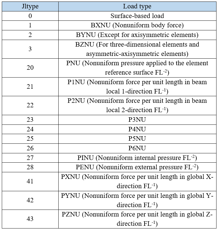
9. Jltyp
A key that specifies the type of distributed load. The load type can be categorized as a body force, a surface-based load, or an element-based surface load. An overview of the definition of load type is presented in the table below:
10. Sname
Surface name for a surface-based load definition (JLTYP=0). In the case of a body force or an element-based load, the surface name is provided as an empty value.
2. DLOAD & VDLOAD Differences
- Type of Solver is the most important distinction of DLOAD & VDLOAD subroutines. The DLOAD subroutine is in Abaqus/Standard solver while the VDLOAD subroutine is in Abaqus/Explicit.
- Variables of DLOAD & VDLOAD subroutines are different, which we have discussed already.
Don’t you want to know how you can How to convert DLOAD to VDLOAD and vice versa?
3. DLOAD & VDLOAD-Specific Requirements
There are some system and software prerequisites that allow you to use the DLOAD & VDLOAD subroutines:
- Abaqus Version Compatibility: Confirm that your subroutine aligns with your Abaqus version.
- Fortran Compiler: A supported compiler is essential for coding and linking the subroutine.
To use DLOAD & VDLOAD subroutines in Abaqus effectively, a basic to intermediate knowledge of Fortran is typically required. Specifically, you should be comfortable with:
- Understanding Fortran syntax means knowing how to write and structure Fortran code.
- Writing and modifying subroutines.
- Handling input/output means knowing how to read from and write to files or communicate with Abaqus’ input and output.
However, you don’t need to be an expert in Fortran to use subroutines in Abaqus, but you should be able to read and understand existing examples, modify them as needed, and debug basic issues. If you’re new to Fortran, start by learning the fundamentals, such as loops, arrays, conditionals, and function calls, which are commonly used in Abaqus subroutines. You can start learning by the following article:
Abaqus Fortran “Must-Knows” for Writing Subroutines
4. Implementing the Abaqus DLOAD & VDLOAD Subroutines (Step by Step Guide)
There are various steps to implement and use the Abaqus DLOAD & VDLOAD subroutines. Using the DLOAD & VDLOAD subroutines in Abaqus involves a systematic process, from setting up the input file to running and debugging the simulation. Here’s a detailed guide:
Step 1: Set Up the Input File
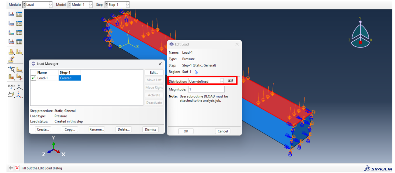
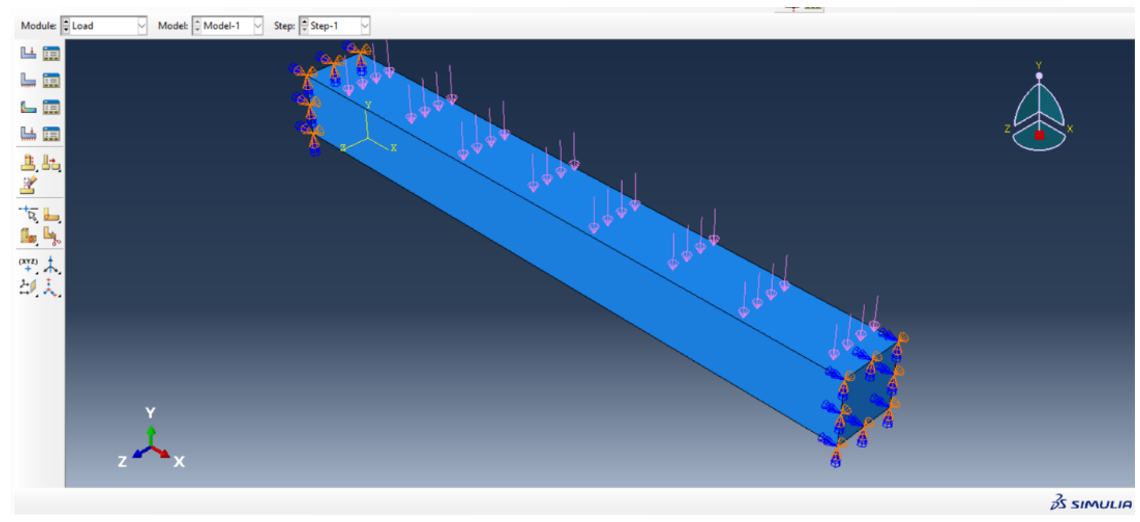
To begin, you need to set up your Abaqus simulation. The first, define the geometry and assign materials and properties. After that create a mesh and apply the boundary conditions. Now in the loads stage, you should determine the load distribution as user-defined as shown in Figure 5.
Do you want more examples of DLOAD and VDLOAD subroutines? check out the tutorial below for 5 more examples.

Figure 5: Load distribution for DLOAD & VDLOAD subroutines
Step 2: Write the Subroutine
The core of this process is the Fortran subroutine, where the load definition is implemented. In the DLOAD & VDLOAD subroutines, you can program a constant, time-dependent, or spatially varying load based on the input parameters provided by Abaqus. It is enough to copy the user subroutine interface and enter the desired force formula in it.
Example: if you have a sinusoidal distributed loading along the x direction and applied to the beam with a 10 × 10 cm section and 100 cm length, such as the following equation:
It will be written in the DLOAD subroutine as shown below.
SUBROUTINE DLOAD(F,KSTEP,KINC,TIME,NOEL,NPT,LAYER,KSPT,
1 COORDS,JLTYP,SNAME)
C
INCLUDE 'ABA_PARAM.INC'
C
DIMENSION TIME(2), COORDS (3)
CHARACTER*80 SNAME

!SIN DISTRIBUTED LOAD:
F=SIN((3.14159*COORDS(1))/1000)

RETURN
END
Step 3: Compile and Link
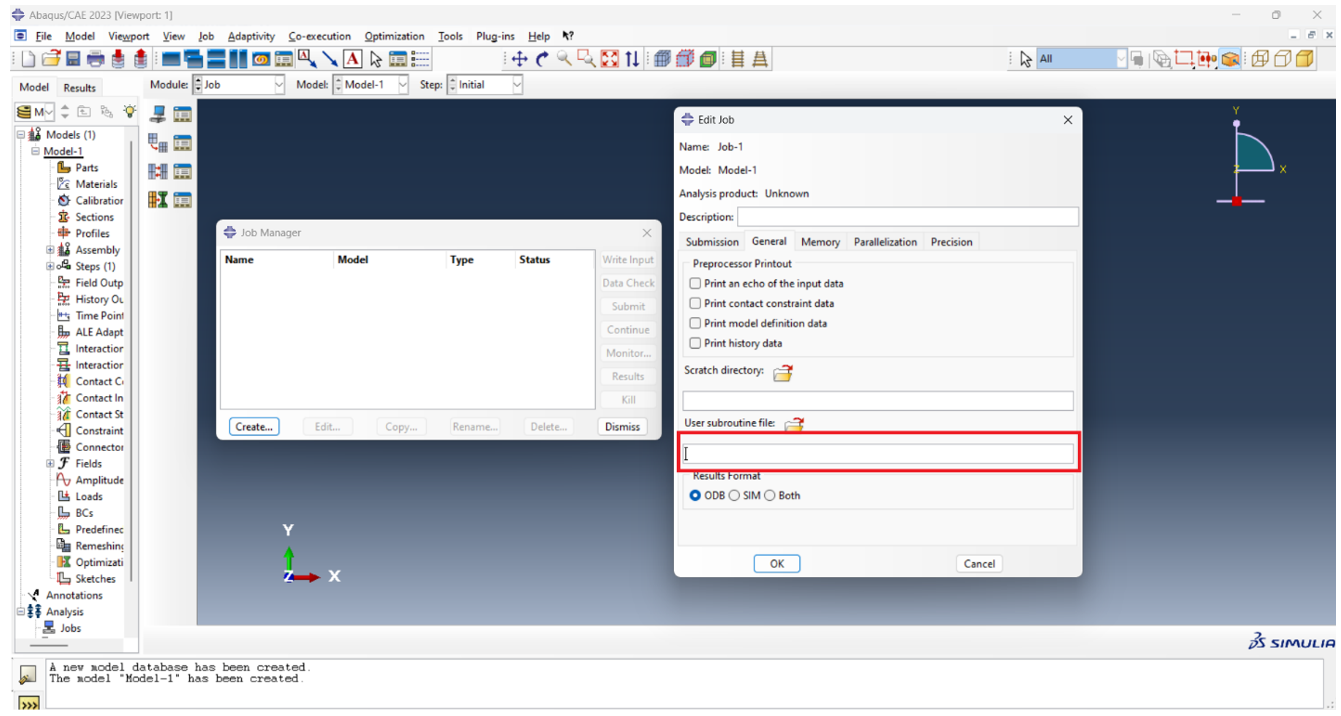
Once the subroutine is written, it must be compiled and linked to Abaqus (As illustrated in Figure 6). This step ensures that ABAQUS can call the subroutine during the simulation. Use a supported Fortran compiler (e.g., Intel Fortran or GNU Fortran) to compile the subroutine into an object file.
Figure 6: How to call the subroutine file in ABAQUS
Step 4: Run and Debug
After compiling and linking, run the simulation and monitor for potential issues. Run the simulation using Abaqus, ensuring that the job references the user subroutine. Check for errors or warnings in the Abaqus log file. Ensure that the subroutine behaves as intended by verifying results such as load distribution and convergence. If issues arise, modify and refine the subroutine logic. Debugging may involve checking input parameters, refining the load calculations, or adjusting the subroutine structure. Test with smaller models to validate functionality before applying to complex simulations.
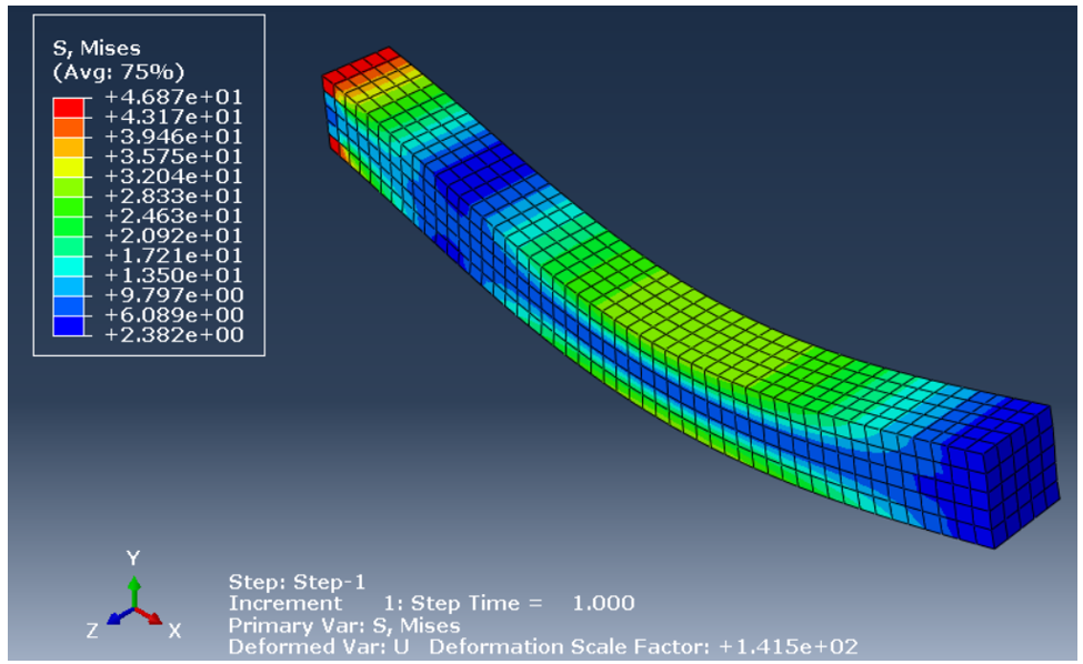
Example: For the beam subjected to the sinusoidal distributed loading which is explained in step 2, the following results are obtained after running the simulation:
Figure 7: Results of the simulation
I know, this was a very simple example, right? it is not even considered an example if you ask me; so, how about a more sophisticated example like “Simulation of Hydroforming with Advanced functional fluid pressure load“
5. Applications of the DLOAD & VDLOAD Subroutines
The DLOAD Subroutine is widely used in various fields of engineering.
Structural Engineering Applications
- Simulating distributed load on bridges same as a clamped beam (Figure 8)
- Simulating wind pressures on tall buildings.
- Modeling seismic loads with time-dependent characteristics.
Figure 8: Distributed load on clamped beam
Aerospace and Automotive Engineering
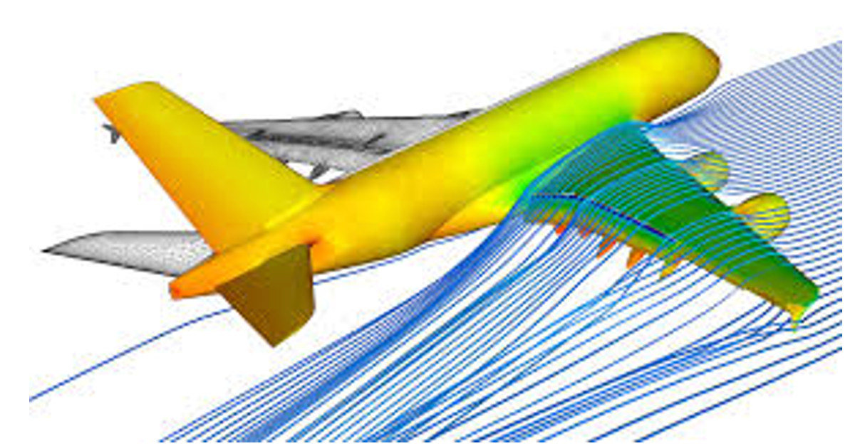
- Analyzing pressure loads on aircraft wings in fluid flow simulations (Figure 9).
- Simulating tire-road interactions on uneven surfaces.
Figure 9: Pressure loads on aircraft wings [Ref]
Energy and Environmental Uses
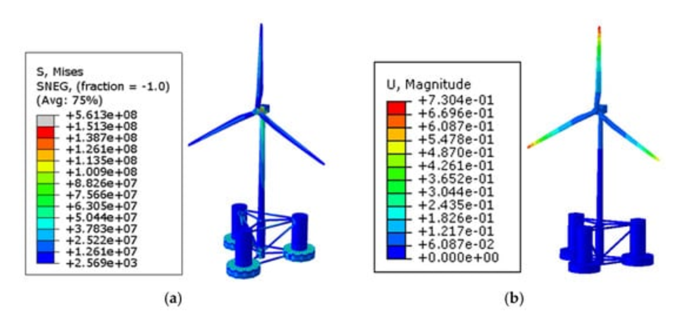
- Modeling wave loads on offshore structures (Figure 10).
- Simulating pressure changes in geothermal systems influenced by temperature.
Figure 10: Modeling wave loads on offshore wind turbine [Ref]
6. Conclusion
This article focused on the DLOAD and VDLOAD subroutines in Abaqus, which allow users to define complex, user-defined loading conditions beyond the standard options available in Abaqus. These subroutines provide flexibility for applying spatially and temporally varying loads, essential for accurately modeling real-world engineering scenarios.
The article begins by explaining the DLOAD and VDLOAD subroutine interfaces, highlighting the different parameters required, such as F, KSTEP, KINC, TIME, NOEL, NPT, and others for DLOAD, and value(nBlock), stepTime, totalTime, velocity, and dirCos for VDLOAD. It emphasizes the importance of correctly interpreting these variables to define load magnitudes and distributions accurately.
Next, it describes the differences between DLOAD and VDLOAD, particularly their respective use in Abaqus/Standard and Abaqus/Explicit solvers, and outlines the system requirements, such as compatibility with the Abaqus version and a Fortran compiler. The article then provides a step-by-step guide for implementing these subroutines, starting from setting up the input file, writing the subroutine in Fortran, compiling and linking it to Abaqus, and finally running and debugging the simulation.
Several practical examples are presented, including the application of a sinusoidal distributed load and simulations of various engineering scenarios, such as structural, aerospace, and energy applications, demonstrating their broad utility.
By the way, you can always find more info about the subroutines in Abaqus documentation.
Do you want to learn DLOAD and VDLOAD subroutines step by step through tutorial videos with 5 Practical examples? 5 Examples!! Of course, you’ll get subroutines files and other files for each example. Just Click Below.
 |
|
The CAE Assistant is committed to addressing all your CAE needs, and your feedback greatly assists us in achieving this goal. If you have any questions or encounter complications, please feel free to share it with us through our social media accounts including WhatsApp.

