
Fracture & Damage Mechanics
1. What is fracture mechanics? Abaqus Fracture analysis
In simple terms, fracture mechanics is concerned with understanding how and why materials fracture, and predicting the conditions under which failure is likely to occur. It is also used to investigate the causes of failures in materials and to develop strategies for preventing failures in the future. The CAE Assistant team fully introduces Fracture analysis, Abaqus fracture and Abaqus damage tutorials in this post. Abaqus damage | Fracture analysis | Damage simulation | Fracture simulation
Here, we will explore the fundamentals of fracture mechanics, including the different types of fractures, the mechanics of crack propagation, and the theories and models used to predict failure. We will also discuss the practical applications of fracture mechanics, such as the design of safer and more reliable structures and the development of advanced materials with improved fracture resistance.
| In summary, damage refers to any alteration in the material’s properties, while fracture and crack specifically refer to types of failure that occur under different conditions of stress and loading. Failure is the ultimate consequence of material degradation, and can occur due to a variety of factors. |
But before we go any further, let’s define the concept of these words one and for all: Damage, Fracture, Crack, and failure; Damage, fracture, and crack are all related to the deformation and failure of materials, but they describe different types of phenomena.
- Damage: Refers to any change or degradation in a material’s properties due to exposure to external factors like stress, temperature, or chemical agents. Damage can reduce the material’s strength and integrity over time, but may not necessarily lead to immediate failure. Abaqus damage models are discussed in this post.
- Fracture: Refers to the separation or breaking of a material due to excessive stress or loading. Fracture can occur suddenly or progressively, and may be ductile (plastic deformation before fracture) or brittle (little or no plastic deformation before fracture). Note that the word “Abaqus fracture simulation” typically involves modeling and analyzing the behavior of materials and structures when subjected to loading conditions that could lead to crack initiation and propagation. introduction to fracture analysis is fully discussed in this post.
- Crack: Refers to a type of fracture that occurs as a result of tensile stresses, typically in the form of a small, linear fissure or discontinuity. Cracks can propagate and grow over time, leading to eventual failure of the material. When we mention “crack” in the context of Abaqus(Abaqus crack), we are referring to different aspects related to the analysis of cracks or fractures in materials and structures.
- Failure: Refers to the point at which a material or structure can no longer support the loads applied to it, resulting in a loss of functionality. Failure can occur due to a variety of factors, including damage, fracture, or a combination of both.
FRACTURE MECHANICS
1.1 Why do we need to know fracture mechanics?
We need fracture mechanics for several reasons:
- Safety: Fracture mechanics helps us design safer and more reliable structures by predicting the conditions under which failure is likely to occur and developing strategies for preventing failures in the future. Through fracture analysis, By understanding how materials behave under different loading conditions, we can design structures that can resist failure and protect human life and property.
- Efficiency: Fracture mechanics helps us optimize the use of materials and minimize waste. By understanding the mechanics of crack propagation, we can design structures that use materials efficiently and avoid overdesigning. Software tools like Abaqus are invaluable for enhancing efficiency, as Abaqus crack simulations offer an effective approach to comprehending crack propagation.
- Innovation: Fracture mechanics is a key driver of innovation in materials science and engineering. Through fracture analysis and By developing new materials with improved fracture resistance, we can create new opportunities for applications and advance the state of the art in many fields.
- Failure analysis: Fracture analysis helps us investigate the causes of failures in materials and structures and develop strategies for preventing failures in the future. By understanding the mechanics of crack propagation, as the context of “Abaqus crack”, we can identify the root causes of failures and develop strategies for avoiding similar failures in the future. Abaqus fracture simulation is a valuable tool in this process, aiding us along the way(discussed further).

1.2 The classification of the fracture mechanics
Fracture mechanics can be classified into two main categories based on the material behavior:
- Linear Elastic Fracture Mechanics (LEFM): In LEFM, the material is assumed to behave in a linearly elastic manner, which means that it deforms elastically under a small load and returns to its original shape when the load is removed. LEFM assumes that the material near the crack tip behaves linearly elastic, meaning that the stress-strain relationship is linear and reversible. In LEFM, the stress intensity factor (SIF) or the strain energy release rate at the crack tip is calculated to predict the critical stress or displacement required for crack initiation and growth. Fracture analysis using LEFM is typically used for analyzing brittle materials, such as ceramics and glasses, where the material behavior can be accurately modeled using linear elastic assumptions.
- Elastic-Plastic Fracture Mechanics (EPFM): In EPFM, the material is assumed to behave in an elastic-plastic manner, which means that it deforms plastically under load, and has a permanent deformation when the load is removed. EPFM assumes that the material near the crack tip behaves elastically-plastically, meaning that the stress-strain relationship is non-linear and irreversible. In EPFM, the J-integral or the crack tip opening displacement (CTOD) is calculated using plastic zone size correction factors to predict the critical stress or displacement required for crack initiation and growth. EPFM is typically used for analyzing ductile materials, such as metals, where significant plastic deformation occurs.
In summary, LEFM and EPFM are two branches of fracture mechanics used to analyze the behavior of materials under loading, but they make different assumptions about the material behavior near the crack tip. LEFM assumes linear elastic behavior, while EPFM accounts for elastic-plastic behavior. We have provided a free course on Abaqus tutorials, and we have also discussed Abaqus fracture simulation. If you are interested in learning more about Abaqus fracture simulation, we recommend clicking on the green button below.

1.3 Types of Fracture Fracture Analysis
Fracture mechanics can also be classified based on the type of fracture, such as:
- Ductile fracture: This type of fracture occurs in materials that can undergo significant plastic deformation before fracturing. Ductile fracture is commonly observed in materials such as metals and polymers, which can undergo large strains before fracturing. Ductile fracture is typically characterized by the formation of necking and void growth before the final fracture occurs.
- Brittle fracture: This type of fracture occurs in materials that have little or no plastic deformation before fracturing. Brittle fracture is commonly observed in materials such as ceramics and glasses, which are relatively strong but do not undergo significant plastic deformation before fracturing. Brittle fracture is typically characterized by the formation of a crack that propagates rapidly through the material, leading to sudden failure.
- Fatigue fracture: This type of fracture occurs due to cyclic loading and the accumulation of damage over time. Fatigue fracture is commonly observed in materials that are subjected to repeated loading and unloading, such as metals used in aircraft structures or turbine blades. Fatigue fracture is typically characterized by the formation of small cracks that grow over time until a critical size is reached, leading to sudden failure.
- Creep fracture: This type of fracture occurs due to long-term exposure to high temperature and stress, causing gradual deformation and eventual failure. Creep fracture is commonly observed in materials that are subjected to high temperatures and stresses over long periods, such as turbine blades in power plants. Creep fracture is typically characterized by the gradual deformation of the material over time, leading to the formation of cracks and eventual failure.
So, the behavior of a crack, such as its rate of propagation, does indeed specify the type of fracture. To simulate this, we need powerful software. Abaqus crack simulations are great because they’re really good at understanding and showing us how these cracks grow.
Now that you have a good understanding of the fracture mechanics overview, let’s delve into the fracture analysis methods required for Abaqus fracture simulation.
1.4 Fracture analysis methods
Fracture analysis methods are used to analyze the behavior of materials under loading and to predict the critical stress or displacement required for crack initiation and growth. Linear Elastic Fracture Mechanics (LEFM) methods assume linear elastic behavior near the crack tip, while Elastic-Plastic Fracture Mechanics (EPFM) methods account for elastic-plastic behavior. LEFM methods typically involve calculating the stress intensity factor (SIF) or the strain energy release rate at the crack tip, while EPFM methods involve calculating the J-integral or the crack tip opening displacement (CTOD) using plastic zone size correction factors. Other fracture analysis methods include cohesive zone modeling, continuum damage mechanics (CDM), and fracture toughness testing. Some of the mentioned methods could be used in both LEFM and EPFM but with their proper modifications.
In the following, the most important methods will be sufficiently explained.
1. Stress Intensity Factor (SIF)
The stress intensity factor (SIF) method is a fundamental concept in fracture mechanics that is used to predict the behavior of materials near the crack tip. It is based on the assumption that the material behavior near the crack tip is linearly elastic, which is valid for brittle materials such as ceramics and glasses. Read More
2. Energy approach
The energy method involves analyzing the energy balance between the energy required to create new surfaces due to crack propagation and the energy released by the stresses around the crack tip. It is a general approach that can be applied to both brittle and ductile materials. Read More
3. J-Integral
The J-integral is a mathematical concept used in fracture mechanics to quantify the amount of energy required to create new crack surfaces and to deform the material near the crack tip. It is a key concept in Elastic-Plastic Fracture Mechanics (EPFM) and Read More
4. Fracture toughness
Fracture toughness is a fundamental material property in fracture mechanics that describes the ability of a material to resist the propagation of a crack. It is a measure of the material’s resistance to fracture when subjected to a high-stress load. Read More
5. Crack Tip Opening Displacement (CTOD)
The Crack Tip Opening Displacement (CTOD) method is a measure of the amount of displacement or opening that occurs at the tip of a crack when a load is applied. The CTOD method is particularly useful for analyzing the behavior of ductile materials, Read More
6. R-curve
The R-curve is a fracture mechanics concept that describes the relationship between the crack growth resistance and the crack extension in a material. It is a measure of the material’s ability to resist crack propagation as the crack grows and is commonly used in Elastic-Plastic Fracture Mechanics (EPFM).Read More

This CAE Assistant training package provides step-by-step tutorials on multiple crack propagation modeling methods, including XFEM, for various materials such as concrete, steel, dams, and bones. These tutorials cover different loading conditions and how to work with the DLOAD subroutine. Each tutorial comes with all the necessary files and an English video guide that explains every step in detail. The tutorials are comprehensive and cover everything from the beginning to the end.
1.5 What are the three modes of fracture?
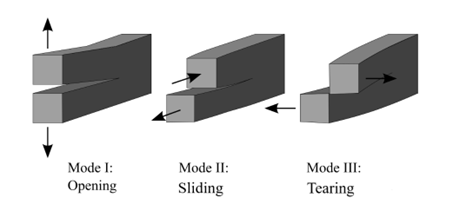
The term “fracture modes” describes the way crack tip stresses are separated into three different types of loads, also known as “modes”. There are three fracture modes:
- Mode I fracture: Also known as opening mode or tensile mode fracture. In this mode, the crack surfaces are pulled apart, causing the crack to open perpendicular to the direction of the applied load. Mode I fracture is often associated with ductile materials such as metals and polymers.
- Mode II fracture: Also known as sliding mode or in-plane shear mode fracture. In this mode, the crack surfaces slide past each other in a direction parallel to the direction of the applied load. Mode II fracture is often associated with materials that are strong in shear, such as composites.
- Mode III fracture: Also known as tearing mode or out-of-plane shear mode fracture. In this mode, the crack surfaces move in opposite directions parallel to the direction of the applied load. Mode III fracture is often associated with materials that are brittle and have a low resistance to shear.
It is important to note that in reality, a fracture may involve a combination of these modes, depending on the material properties, loading conditions, and geometry of the structure. Nevertheless, grasping the modes of fracture is crucial for understanding “Abaqus Fracture Simulation,” predicting and preventing failures in materials and structures, and designing safer and more reliable structures capable of withstanding various loading conditions.


1.6 Fracture analysis techniques in the FEM | Fracture simulation – Abaqus Fracture
In finite element analysis, the analysis techniques are used to apply the required fracture analysis methods such as stress intensity factor and J-integral. In fracture analysis using FEA in a software like Abaqus, there are several techniques that can be used to analyze the behavior of materials near cracks. Some of these techniques include:
1. Crack tip element:
This technique involves using a special type of finite element near the crack tip to model the behavior of the material under high stress concentrations. The crack tip element is typically designed to capture the singularity of the stress field near the crack tip and can be used to calculate the stress intensity factor and predict the critical stress required for crack initiation and growth. Read More
2. Cohesive zone modeling (CZM):
Cohesive zone models are a type of computational model used in the field of fracture mechanics to simulate the behavior of materials under loading and predict their failure mechanisms (fracture analysis). In these models, the material is divided into two distinct regions: the bulk material and the cohesive zone. The bulk material is assumed to behave elastically, Read More
The training package covers the cohesive element ABAQUS and cohesive surface Abaqus in detail, with a focus on modeling using the traction-separation method. Two methods, element-based and surface-based, are used to simulate adhesives, each with its own benefits and drawbacks. This Abaqus Fracture package includes theories for all adhesive behaviors, from the elastic zone to damage initiation, progressive damage, and element removal. It also fully explains the equations, damage initiation criteria, and adhesive damage progression used in the simulations.
3. Extended finite element method (XFEM):
The Extended Finite Element Method (XFEM) is a numerical technique that is used in fracture mechanics analysis to model crack propagation in complex geometries. Also, it is one of the Abaqus techniques for fracture analysis. It is a variant of the finite element method that can handle discontinuities such as cracks without the need for mesh refinement. Read More
This is another of Abaqus fracture packages which provides step-by-step tutorials on Abaqus crack simulation, including XFEM, for various materials such as concrete, steel, dams, and bones. These tutorials cover different loading conditions and how to work with the DLOAD subroutine. Each tutorial comes with all the necessary files and an English video guide that explains every step in detail. The tutorials are comprehensive and cover everything from the beginning to the end.
DAMAGE MECHANICS
Damage Mechanics
2. What is damage mechanics? Abaqus Damage simulation
Damage mechanics is a branch of mechanics that deals with the analysis and modeling of the progressive damage and failure of materials under loading. It seeks to understand the mechanisms of damage and how they lead to the eventual failure of the material.
Damage mechanics is concerned with various types of damage that can occur in materials, such as cracks, voids, and inelastic deformation, and how these types of damage evolve over time. It uses continuum mechanics models to describe the behavior of the material and its response to external loading. Abaqus damage models are fully discussed here and in the related training packages.
Read More: ANSYS vs ABAQUS: Difference between Ansys and Abaqus
The main goal of damage mechanics is to develop models that can predict the onset and evolution of damage in a material, as well as the ultimate failure of the material. These models can be used to optimize the design of structures and materials for specific applications, such as aerospace, automotive, and civil engineering. Read More
2.1 What is the difference between Damage mechanics and Fracture mechanics?
Damage mechanics and fracture mechanics are two related but distinct fields of study within the broader field of mechanics.
Fracture mechanics focuses on the study of crack propagation and the conditions that lead to the ultimate failure of a material due to the growth of cracks. Read More

2.2 The classification of Damage Mechanics
Damage mechanics is a broad field of study that encompasses a wide range of phenomena related to the accumulation and evolution of damage in materials. One way to classify different types of damage is based on the scale at which they occur. Some common classifications of damage mechanics include:
- Microscale damage: This refers to damage that occurs at the microstructural level, such as voids, cracks, or other defects in the material. Microscale damage can affect the mechanical properties of the material, and can lead to further damage and failure if left unchecked.
- Mesoscale damage: This refers to damage that occurs at the scale of individual grains or clusters of grains within the material. Mesoscale damage can include features such as grain boundary cracking or dislocation structures.
- Macroscale damage: This refers to damage that is visible to the naked eye, such as cracks or deformations in the material. Macroscale damage can be caused by a variety of factors, including fatigue, corrosion, or impact loading.
2.3 Damage Types based on loading condition
Another way to classify damage in materials is based on the type of loading or deformation that causes the damage. Some common types of damage are described below.
By understanding the different types and scales of damage that can occur in materials, researchers and engineers can better simulate the behavior of materials, such as fracture simulation under specific loads, develop strategies to prevent or mitigate damage, and design stronger and more resilient materials and structures. Abaqus damage models can show you each type of damage.
1. Fatigue damage:
This is damage that occurs over time due to repeated loading and unloading cycles. Fatigue damage can lead to the growth of cracks and other defects in the material, and can eventually result in failure.

2. Creep damage:
This is damage that occurs over time due to sustained loading at high temperatures. Creep damage can cause the material to deform and weaken, leading to eventual failure.

3. Impact damage:
This is damage that occurs due to a sudden, high-energy impact, such as a collision or explosion. Impact damage can cause cracks, fractures, and other types of damage to the material.

4. Corrosion damage:
Damage occurs due to chemical reactions between the material and its environment. Corrosion damage can weaken the material and make it more susceptible to other damages.


2.4 Damage models in Abaqus | Abaqus damage
The Abaqus damage model is a type of damage model that uses mathematical formulations or algorithms to predict the evolution of damage in materials and structures under different loading and environmental conditions. Abaqus damage is based on the principles of continuum mechanics and takes into account the effects of various types of damage, such as cracking, void formation, and material degradation, on the mechanical behavior of the material. Abaqus damage is widely used in the design and maintenance of materials and structures, as it provides a predictive tool for assessing the long-term durability and reliability of these components. By using Abaqus damage, researchers and engineers can gain a better understanding of the mechanisms of damage and failure in materials and develop effective strategies for preventing and mitigating damage.
| There are several different types of damage models, each with their own strengths and limitations. Some common types of damage models include Abaqus damage models, continuum damage mechanics (CDM) models, fracture mechanics models, fatigue models, and damage accumulation models. These models, including Abaqus damage, can be used to predict the development of damage under different loading conditions and to guide the development of new materials and structures with improved resistance to damage. |
Continuum Damage Mechanics (CDM) models
The Continuum Damage Mechanics (CDM) model is a popular approach used in damage mechanics to describe the evolution of damage in materials. CDM is a macroscopic model that considers damage as a continuous process, where the material’s degradation is represented by a scalar damage parameter. The CDM model assumes that damage in a material occurs due to the accumulation of microcracks and voids, which reduce the cross-sectional area available for load-bearing and, therefore, the material’s strength. The model takes into account the effects of stress, strain, and material properties on the evolution of damage, and it is widely used in the study of damage in composite materials, metals, and other materials.
The CDM model involves the use of constitutive equations that describe how the material properties change as damage accumulates. These equations can be derived from experimental data or based on theoretical models of the material’s behavior. The model also requires a set of damage evolution equations that describe how the damage parameter changes as a function of the applied loads and other factors.
The CDM model is often used in conjunction with finite element analysis (FEA) to predict the behavior of damaged structures under different loading conditions. By using the CDM model, engineers can gain a better understanding of how damage affects the mechanical behavior of materials and structures, and develop strategies for preventing or mitigating damage.
The Gurson-Tvergaard-Needleman (GTN) model
The Gurson-Tvergaard-Needleman (GTN) model is a widely used constitutive model in damage mechanics, particularly for predicting the behavior of ductile materials. The model was developed in the 1970s by Yves-Gerard Gurson, and later extended by Niels Tvergaard and Jonathan Needleman.
The GTN model assumes that damage in a material occurs due to the growth and coalescence of voids under tensile loading. The model describes the behavior of the material as a combination of elastic, plastic, and damaged regions, and takes into account the effects of stress triaxiality and strain hardening on the growth and coalescence of voids. The model is based on the concept of a porous continuum, where the solid material is assumed to be surrounded by a continuous distribution of voids. The model uses a scalar damage variable to track the evolution of damage in the material, and includes a set of damage evolution equations that describe how the damage variable changes as a function of the applied loads and other factors.
The GTN model has been widely used to predict the onset and propagation of ductile fracture in a variety of materials, including metals and alloys. The model has also been extended to include the effects of shear loading and multiaxial stress states, and has been used in the design of materials and structures with improved resistance to damage and fracture.

This package focuses on implementing and developing Lemaitre’s continuum damage mechanics framework for ductile materials in ABAQUS using the VUMAT subroutine. ABAQUS provides users with a range of element types, material models, and efficient equation solvers. The package covers a fully coupled constitutive elastic-plastic-damage model and describes the modeling of ductile damage in detail. The package incorporates the effect of micro-crack closure, which can slow down damage growth under compression, and treats constitutive modeling within the framework of continuum damage mechanics (CDM). One of the best training packages about Abaqus damage modeling in the ductile material.
2.5 Abaqus Damage criteria
Damage criteria are mathematical expressions or algorithms used to predict the onset and progression of damage in materials and structures. These criteria are based on the principles of continuum mechanics and take into account the effects of various types of damage, such as cracking, void formation, and material degradation, on the mechanical behavior of the material.
Abaqus damage criteria, in particular, are a set of damage criteria implemented within the Abaqus finite element software package. These criteria are used to predict the behavior of materials and structures under different loading conditions, and to guide the development of new materials with improved resistance to damage. Abaqus damage criteria include the Johnson-Cook model, the Rousselier model, the Cockcroft-Latham model, and the Mohr-Coulomb model, among others. These criteria take into account factors such as stress, strain, and strain rate, and are calibrated using experimental data to accurately describe the behavior of specific materials.
| By using Abaqus damage criteria, engineers and researchers can gain a better understanding of how damage affects the mechanical behavior of materials and structures, and develop effective strategies for preventing or mitigating damage. Abaqus damage criteria are widely used in the design and optimization of materials and structures for a wide range of engineering applications, from aerospace to automotive engineering. |
Abaqus offers various damage models and criteria which can be employed to imitate the conduct of materials under varying loading scenarios. Below is a list of all the damage criteria that Abaqus supports:
1.Maximum Principal Stress (MPS) criterion: The MPS criterion is a method for predicting failure that is triggered when the maximum principal stress in the material surpasses a specific limit. It is primarily utilized for brittle materials and is derived from the notion that failure arises when the tensile stress surpasses the strength of the material.
2.Maximum Principal Strain (MPS) criterion: When the maximum principal strain in the material surpasses a certain threshold, this criterion anticipates failure. The MPS criterion is often utilized for ductile materials and is grounded on the belief that failure transpires when the material undergoes a particular degree of deformation.
3. Modified Mohr-Coulomb (MMC) criterion: The MMC criterion is a method that forecasts failure when the maximum shear stress in the material goes beyond a particular threshold. It is typically employed for rocks and soils and is based on the concept that failure arises when the shear stress surpasses a specific level.
4. Drucker-Prager (DP) criterion: The DP criterion expects failure when the deviatoric stress in the material surpasses a specific threshold. This criterion is frequently utilized for ductile materials like metals and relies on the belief that failure occurs when the material undergoes a certain level of plastic deformation.
5.Continuum Damage Mechanics (CDM) model: The CDM model explains the conduct of materials undergoing damage due to the emergence and merging of microcracks. This model is based on the concept that damage accumulates as the material goes through loading and can be utilized to anticipate and track the development of damage in a material.
6. Johnson-Cook (JC) model: The JC model is a damage model that combines a failure criterion and a plasticity model to simulate the behavior of materials exposed to high temperatures and strain rates. This model considers the material’s properties like thermal softening, strain hardening, and strain rate sensitivity, and can be practical for simulating the conduct of materials under extreme loading conditions.
7. Puck criterion: The Puck criterion predicts failure when the maximum hydrostatic stress in the material surpasses a particular limit. It is usually employed for brittle materials and is based on the notion that failure arises when the material undergoes a certain level of compression.
8. Tsai-Wu criterion: The Tsai-Wu criterion is a failure criterion for composite materials that accounts for both stress and strain components. The criterion predicts failure when the combined stress and strain components go beyond a certain limit, taking into consideration the material’s properties and orientation.
9. Hashin criterion: The Hashin criterion is another failure criterion for composite materials that considers the properties and alignment of the fibers and matrix. The criterion predicts failure when the stresses and strains in the material surpass certain thresholds, taking into account the properties of the fiber and matrix.
10. Johnson-Cook Damage model: The Johnson-Cook Damage model is a damage model that combines the Johnson-Cook plasticity model with a damage criterion. The model predicts damage accumulation and failure in materials exposed to high temperatures and strain rates, taking into account the material’s properties and the loading conditions.
This package focuses on Johnson Cook’s plasticity, damage initiation, and progressive damage, which are available in Abaqus. Two workshops demonstrate how to use the Abaqus model for Johnson-Cook theory. However, sometimes new theories require changes to the Johnson-Cook equations. This package teaches how to use the Abaqus model for Johnson-Cook theory and write subroutines for implementing Johnson-Cook plasticity and damage initiation, as well as Johnson-Cook progressive damage. Two subroutines are provided for this purpose.

This package covers the topic of hardening plasticity within the Abaqus software. It explains how to implement hardening using either Abaqus material models or subroutines such as UMAT or UHARD. The package emphasizes the use of subroutines for hardening definitions, as they provide a more professional approach. The goal is to make users familiar with these subroutines for defining hardening in their simulations.
Go to all Abaqus tutorials, and learn more about Units in Abaqus or Abaqus units; learn how to use Abaqus student edition; read more about Fortran Abaqus subroutine; or linking Abaqus Fortran; read about Abaqus reaction force and Abaqus negative eigenvalue.
If you need to get the basics about FEM read the Finite Element Analysis article; Learn about all packages available for Composite Analysis; get the practical examples of the 10 most useful Abaqus subroutines examples; if you need to debug your Abaqus file read debugging Abaqus error.
To solve Abaqus convergence issues, Abaqus Umat writing, Abaqus subroutine writing, running multiple Jobs Sequentially in Abaqus, running quasi-static analysis in Abaqus read each related article.
In this post, we have tried to explain ‘Fracture and Damage Mechanics’ thoroughly so that you can choose the right Abaqus fracture package for your needs. Now, you should understand the different types of fractures and damage, their differences, and how we analyze them (Fracture analysis and Fracture simulation). Also, please share your views with the CAE Assistant experts in the comment section. We really appreciate your feedback, as it helps us improve our tutorials and fulfill all your CAE needs without requiring additional tutorials. Abaqus damage | Fracture analysis | Damage simulation | Fracture simulation
References:
1- Fracture Mechanics, Anderson
2- Fracture Mechanics chapters, ScienceDirect
3- Introduction to Damage Mechanics
4- Handbook of Damage Mechanics
You can have the PDF of this post by clicking on CAE Assistant – Abaqus Fracture mechanic
| ✅ Subscribed students | +80,000 |
| ✅ Upcoming courses | +300 |
| ✅ Tutorial hours | +300 |
| ✅ Tutorial packages | +100 |
Here are the frequently asked questions for this post:
What are the fracture analysis methods?
The most important methods:
- Stress Intensity Factor (SIF)
- Energy approach
- J-Integral
- Fracture toughness
- Crack Tip Opening Displacement (CTOD)
- R-curve
What are the three modes of fracture mechanics?
Mode I fracture: In this mode, the crack surfaces are pulled apart, causing the crack to open perpendicular to the direction of the applied load.
Mode II fracture: In this mode, the crack surfaces slide past each other in a direction parallel to the direction of the applied load.
Mode III fracture: In this mode, the crack surfaces move in opposite directions parallel to the direction of the applied load
What are the four basic types of damage based on boundary conditions?
Fatigue damage: This is damage that occurs over time due to repeated loading and unloading cycles.
Creep damage: This is damage that occurs over time due to sustained loading at high temperatures.
Impact damage: This is damage that occurs due to a sudden, high-energy impact, such as a collision or explosion.
Corrosion damage: Damage occurs due to chemical reactions between the material and its environment.
What is the difference between damage mechanics and fracture mechanics?
Fracture mechanics focuses on the study of crack propagation and the conditions that lead to the ultimate failure of a material due to the growth of cracks. On the other hand, damage mechanics examines the physical and chemical changes that occur within the material as it is subjected to loading and deformation, and how these changes affect the material’s mechanical properties. While fracture mechanics concentrates on the final stages of material failure, damage mechanics seeks to understand the process leading up to failure.
What are the damage initiation criteria for ABAQUS?
- Maximum Principal Stress (MPS) criterion
- Maximum Principal Strain (MPS) criterion
- Modified Mohr-Coulomb (MMC) criterion
- Drucker-Prager (DP) criterion
- Continuum Damage Mechanics (CDM) model
- Johnson-Cook (JC) model
- Puck criterion
- Tsai-Wu criterion
- Hashin criterion
- Johnson-Cook Damage model
Abaqus fracture | Abaqus damage | Fracture analysis | Damage simulation | Fracture simulation