
LPBF Printing Full Guide | FEA with Inherent strain method
Metal Additive Manufacturing (AM) encompasses advanced technologies that create three-dimensional parts layer by layer using metallic materials. Among the various methods, Laser Powder Bed Fusion (LPBF) has gained prominence due to its ability to produce high-precision components with complex geometries. In LPBF, a high-energy laser selectively fuses powdered metal, building up parts layer by layer. The process begins with a thin layer of powder spread across the platform. A laser then scans the layer following a predefined path, melting the powder and solidifying it as it cools. The platform lowers, and another layer of powder is applied, repeating the cycle until the part is complete. However, challenges like residual stresses and distortions have spurred the need for innovative simulation methods. The Inherent Strain Method (ISM) has emerged as a game-changer in this regard, offering a computationally efficient approach to predict and address these issues. This article will focus on these three key concepts so you can click on each section you are interested in:
Metal additive manufacturing simulation with the Inherent Strain Method in Abaqus—a fast, efficient alternative to full thermo-mechanical modeling. This tutorial guides you through Python scripting and Fortran subroutines to accurately predict residual stresses and distortions in LPBF-printed parts, all while cutting down computational costs. With step-by-step workshops and real-world applications, this package offers a practical, cost-effective solution for engineers and researchers looking to refine their simulation skills.
1. Metal Additive Manufacturing (AM)
Metal Additive Manufacturing, also known as 3D printing for metals, refers to the process of building three-dimensional metallic parts layer by layer. It has transformed the way complex metallic parts are designed and produced. Unlike traditional subtractive manufacturing methods that remove material from a larger block, MAM constructs parts from the ground up, layer by layer, based on a digital 3D model. It allows for design flexibility, reduced material waste, reduced lead times, and tailored mechanical properties, making it indispensable for industries like aerospace, automotive, and healthcare.
Key Categories of Metal Additive Manufacturing are:
- Powder Bed Fusion (PBF):
- Laser Powder Bed Fusion (LPBF): Uses a high-powered laser to selectively melt and fuse metal powder.
- Electron Beam Melting (EBM): Employs an electron beam to melt and fuse metal powder.
- Directed Energy Deposition (DED):
- Involves depositing molten material directly onto a substrate using a focused energy source like a laser or electron beam.
These categories represent different approaches to achieving the same goal: creating intricate metal components with high precision and complexity.
2. Laser Powder Bed Fusion (LPBF) Process
LPBF involves rapid heating and cooling cycles, transitioning the material through powder, liquid, and solid states. These transitions result in thermal gradients and residual stresses, leading to potential distortions in the final product. Addressing these challenges is crucial for producing reliable, high-performance components.
The process involves key steps, including:
- Powder Deposition: A thin layer of metal powder is spread across the build platform;
- Laser Scanning: A high-energy laser selectively fuses powder particles according to the cross-sectional geometry of the component; and
- Layer-by-Layer Building: The platform lowers incrementally, and the next layer of powder is applied and fused, gradually building the part.
The Laser powder bed fusion process is influenced by several parameters, including laser power, scan speed, hatch distance, and layer thickness. These parameters significantly affect temperature distribution, residual stress, and distortion in the final part. Experimentally optimizing these parameters is costly and time-intensive, which has led to the adoption of computational modeling and simulation techniques.
We have a tutorial specifically designed for LPBF simulation in Abaqus. The workshop in this tutorial teaches laser powder bed fusion simulation in Abaqus, covering model geometry, material properties, and key process parameters like roller and laser beam speeds. It explains boundary conditions and step-by-step modeling using Abaqus/CAE, integrating “Event series” data with the AM Modeler plug-in. The process includes both thermal and structural analysis, concluding with result evaluation.
The precision of LPBF stems from its ability to control parameters like laser power, scan speed, and layer thickness. These parameters directly influence the quality, density, and mechanical properties of the finished component. LPBF’s ability to produce lightweight structures, reduce material waste, and offer design freedom makes it invaluable for industries such as aerospace, automotive, and medical devices.
2.1. Thermal and Mechanical Phenomena in LPBF printing
During LPBF printing, the material undergoes rapid heating and cooling cycles, transitioning between powder, liquid, and solid states. These transitions result in complex thermal and mechanical interactions, which must be accounted for to predict the final properties of the manufactured part. Key factors include:
- Thermal Conductivity: Dictates how heat propagates through the material during the process;
- Latent Heat: Represents the energy required for phase changes between solid, liquid, and powder states; and
- Specific Heat Capacity: Influences the rate at which the material temperature changes.
These properties are often temperature-dependent and must be meticulously defined for accurate simulation.
Abaqus Tutorial 3D Printing Simulation for LPBF with AM Modeler Plug in
2.2. Challenges in Laser Powder Bed Fusion Simulation Processes
Despite its advantages, LPBF printing comes with challenges, particularly the complexity of thermal and mechanical behaviors during the process. Rapid heating and cooling cycles induce thermal gradients, residual stress, and potential distortions in the fabricated parts. Understanding and predicting these phenomena are crucial for optimizing the process and ensuring the reliability of the final products.
2.3. Thermal-Mechanical Simulations for LPBF
Thermal-mechanical simulations provide insights into the thermal and mechanical behavior of materials during the LPBF process. Two primary numerical approaches are used for simulation:
2.3.1. Detailed Thermal-Mechanical Simulation
This approach involves either fully coupled or partially coupled analyses:
- Fully Coupled Analysis: Simultaneously evaluates thermal and mechanical behaviors. The geometry is modified at each time step, where displacements influence temperature distribution. While this method offers high accuracy, it is computationally intensive, especially for complex geometries.
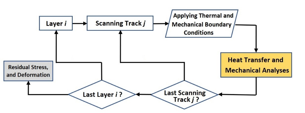
Figure 1: Fully-coupled thermo-mechanical simulation analysis workflow
- Partially Coupled Analysis: Conducts thermal and mechanical simulations independently. A transient heat transfer analysis determines the temperature distribution, which is subsequently applied as a temperature field in quasi-static mechanical analysis. This reduces computational requirements while retaining reasonable accuracy.
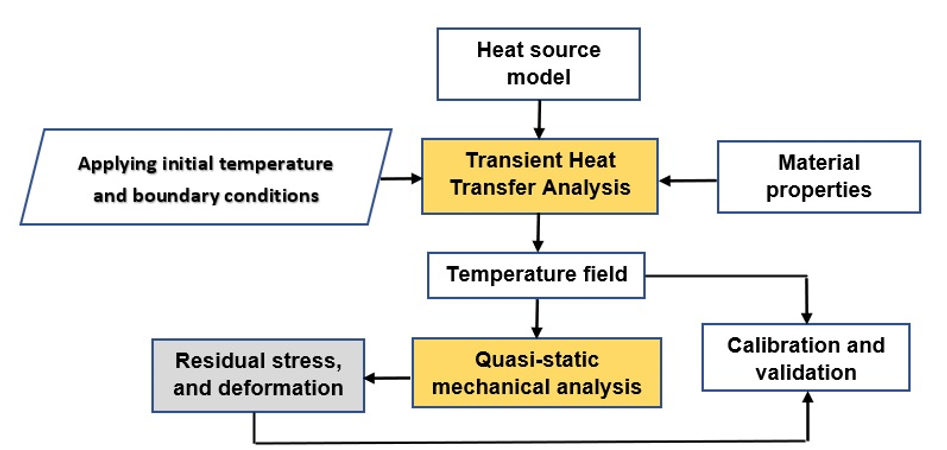
Figure 2: Partially-coupled thermo-mechanical simulation analysis workflow
2.3.2. Inherent Strain Method
This simplified approach is computationally efficient and particularly useful for predicting residual stresses and distortions in large or complex parts. The Inherent Strain Method (ISM) originated in welding mechanics and has been adapted for LPBF simulation. (Full ISM tutorial for metal LPBF simulation in Abaqus)
3. Inherent Strain Method (ISM)
One effective way to simulate and address the challenges in LPBF printing is the Inherent Strain Method (ISM). This technique simplifies the computational analysis of residual stresses and distortions by replacing the complex thermal-mechanical interactions with pre-defined strain values. The inherent strain values are derived from detailed simulations or experiments and represent the accumulated strain induced by the thermal cycles.
The ISM focuses on the key outcomes—stress and deformation—without modeling the entire thermal history, thus reducing computational time and complexity. By dividing the build into layers or tracks, the ISM applies the inherent strain values iteratively, mimicking the layer-by-layer nature of LPBF.
3.1. Significance and Applications of the Inherent Strain Method
The ISM is particularly useful for large-scale simulations and optimization studies where computational efficiency is paramount. By abstracting the thermal and mechanical interactions into manageable datasets, the method enables engineers to predict residual stresses, optimize build strategies, and reduce distortions. It also facilitates the exploration of various process parameters, such as laser power and scan strategies, to minimize defects and improve part performance.
The ISM Efficiently predicts residual stresses and distortions with minimal computational cost
Workflow: Define problem & material properties ➔ Run micro-scale thermal/mechanical simulations (DFLUX/USDFLD) ➔ Extract inherent strain values ➔ Apply strains in macro-scale model via Python scripting ➔ Analyze residual stresses and distortions.

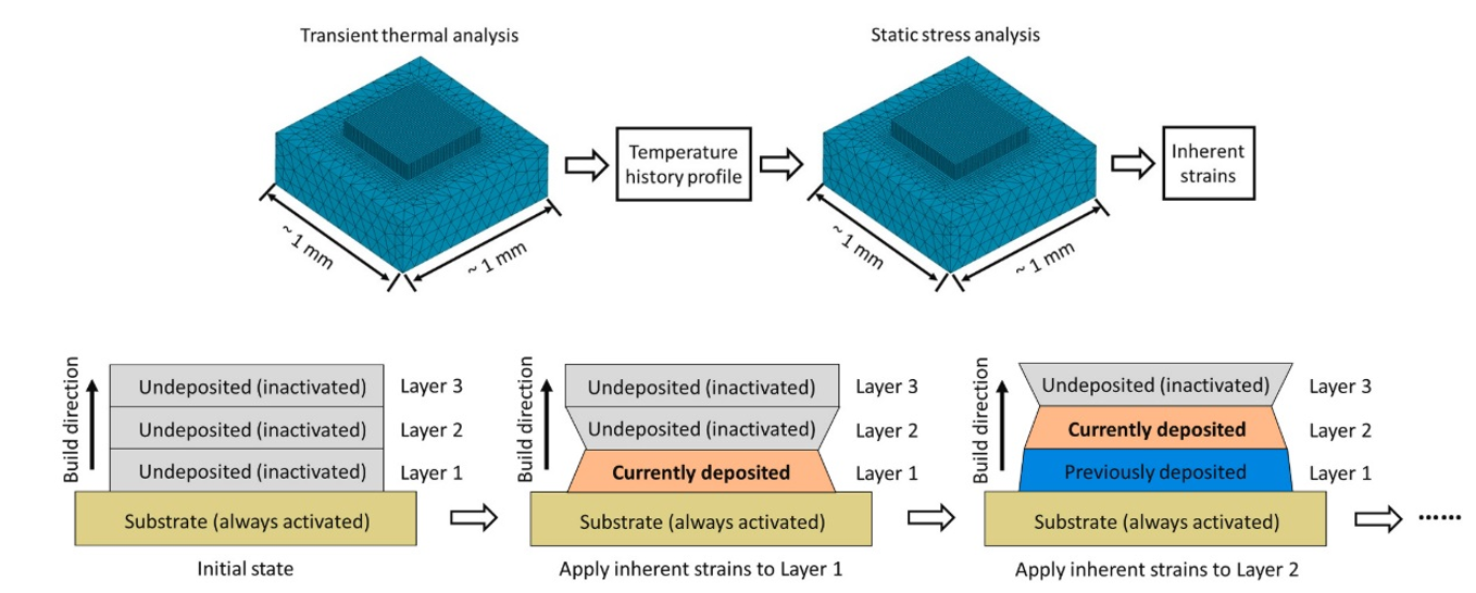
Figure 3: Analysis workflow of the inherent strain method [Ref]
3.2. The Inherent Strain Methodology
The inherent strain method simplifies the LPBF process by separating it into two distinct stages:
3.2.1. Micron-Scale Modeling
- Detailed thermal-mechanical simulations are performed to capture plastic strain tensors at the microscopic level. (Full tutorial and step by step explanation of micro modeling)
- These tensors are extracted and represent the inherent strains caused by thermal and mechanical effects during layer solidification.
3.2.2. Macro-Scale Modeling
- The inherent strain values obtained from the micron-scale model are applied to a macro-scale mechanical model.
- Using a layer-by-layer approach, residual stresses and distortions in the final part are predicted with reduced computational effort.
3.3. Theoretical Background of ISM
The inherent strain method assumes that the total distortion results from the summation of elastic, plastic, thermal, and phase transformation strains. In LPBF, thermal and phase transformation strains often diminish during the cooling phase, leaving plastic strain as the dominant component of inherent strain.
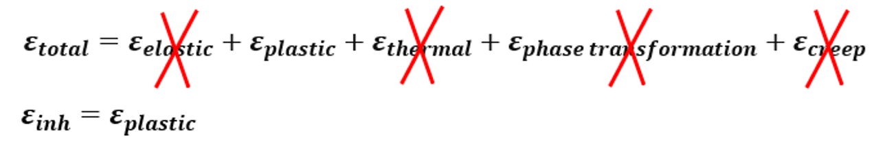
Classical inherent strain method
To enhance accuracy, a modified inherent strain approach incorporates elastic and plastic strains at the intermediate state and residual elastic strains at the steady state. This refinement improves the predictive capability for residual stresses and distortions in laser powder bed fusion simulations.
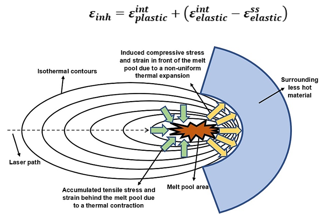
Figure 4: Formation mechanism of the compressive-tensile stress and strain due to thermal expansion and contraction in the melt pool area
3.4. Comparison to Other Methods
Compared to detailed thermal-mechanical simulations, the inherent strain method offers significantly lower computational costs, albeit with reduced accuracy. It is ideal for large-scale simulations where computational resources are a limiting factor.
3.5. Why choose Subroutine Over AM Plugin
While commercial software like Abaqus provides modular plugins for LPBF simulation, such tools often have limitations, including reduced flexibility for defining custom heat source models and temperature-dependent material properties. By employing the inherent strain method and leveraging Python scripting, users can gain greater control and adaptability in their simulations. Besides that the inherent strain method is being used widely in different commercial software, but the underlying algorithms are not clear. So the first objective, is to find out the value of definition for the inherent strain values.
4. Simulation Workflow
The simulation workflow involves two key modeling scales:
- Micron Scale: In this phase, the geometry and process parameters, such as laser power, scanning strategy, and layer thickness, are defined. Thermal analysis predicts temperature distributions, and mechanical analysis extracts inherent strain values. These analyses require precise material property definitions and tailored subroutines (USDFLD and Dflux) to simulate complex thermal-mechanical interactions.
- Macro Scale: Using the extracted inherent strain values, a macro-scale model predicts residual stresses and distortions. The agglomeration approach simplifies the simulation by grouping multiple layers, enabling efficient computation.
From this point forward, our discussion will center around the training package we have developed. You can download it from here, or find similar packages that utilize plugins by clicking here.
4.1. Micro Scale
The modeling uses two layers with a specific scanning strategy for each. The first layer has longitudinal scanning, and the second has transverse scanning. The material used, Inconel 718, is a superalloy widely applied in industries. The geometry and material properties are carefully defined, including dimensions, layer thickness, laser power, and other characteristics.
The thermal and mechanical behavior of the material during the LPBF process is analyzed. The thermal analysis is conducted first to extract temperature distributions, and material properties like thermal conductivity, density, and specific heat are defined, considering their dependence on temperature and state (powder, liquid, or solid).
A subroutine is used to account for changes in material properties during the simulation. This involves defining variables for temperature transitions and updating states during each simulation step. The process uses a heat source model to simulate laser movement, with parameters carefully defined to reflect real-world conditions.
The layers and substrate are assembled, and interactions, boundary conditions (convection and radiation), and constraints are applied. The scanning strategy is implemented using a user-defined code to simulate the laser’s movement over each track. The simulation considers various aspects, such as the laser’s speed, power, and path.
The ISM Efficiently predicts residual stresses and distortions with minimal computational cost
Micro-Scale Modeling Workflow: Define material properties and boundary conditions ➔ Set up thermal and mechanical simulations in Abaqus ➔ Use DFLUX and USDFLD subroutines to model heat flux and field variables ➔ Extract inherent strain values from the simulation results ➔ Analyze and prepare strain data for use in the macro-scale model.
The process concludes with defining cooling times and outputs, like temperature distribution and heat flux. Finally, the simulation is executed, with checks to ensure proper functioning and accurate results. The method enables detailed analysis of LPBF processes, providing insights into temperature effects and material behavior.
Here’s a simplified explanation:
I. Layer Deposition and Melting:
-
- Materials are deposited in layers, with a laser melting each layer to form a solid structure.
- After depositing and melting the first layer, a pause allows it to cool before the next layer is added. The heat from subsequent layers can remelt the previous ones, but this depends on how much heat is applied and for how long.
II. Temperature Control and Layer Behavior:
-
- The process is designed to control the temperature at each layer to ensure proper bonding. The temperature history shows how layers are reheated and solidified as new layers are added.
- Specific materials and process parameters, like laser power and layer thickness, determine how many layers are needed and how they interact thermally.
III. Material Properties:
-
- Material properties, like elasticity and plasticity, change with temperature. These properties are modeled to ensure accurate predictions of how the material behaves under thermal and mechanical stress.
IV. Simulation and Analysis:
-
- A simulation is created to mimic the real-world process. This includes detailed steps for activating elements in the model as the laser moves across layers.
- Python scripts automate much of this, defining activation steps, temperature conditions, and material changes.
V. Output and Refinement:
-
- The results show how the material transitions from powder to liquid to solid, highlighting changes in mechanical properties like stress and strain.
- Inherent strains, caused by heating and cooling cycles, are calculated for macro scale modeling.
4.2. Macro Scale
In this stage, the focus shifts to the macroscale modeling of a cantilever beam to simulate its mechanical behavior during and after layer deposition. The goal is to account for the residual stresses and distortions due to the additive manufacturing process. Here’s how it works:
I. Transition to Macroscale:
-
- After completing the microscale simulation, which provided critical thermal and strain data, these values are integrated into the macroscale model. This involves activating elements (representing layers) based on their thermal state during the simulated build.
II. Layer Modeling:
-
- Instead of modeling each real physical layer (which would be computationally expensive), an approximation method is used. Multiple physical layers are combined into fewer “equivalent layers.” For instance, several layers are grouped together based on their cumulative thickness, reducing the computational burden while preserving accuracy.
III. Material and Mechanical Properties:
-
- The material properties, such as elasticity and thermal expansion, are defined. The data from the microscale simulation informs the anisotropic thermal expansion coefficients, ensuring that the macroscale model accurately reflects material behavior.
IV. Element Activation:
-
- Layers are simulated to be “activated” progressively, representing the deposition process. This involves specifying which parts of the beam become active layer by layer, according to the defined process parameters.
V. Simulation Execution:
-
- After defining the geometry, layers, and material properties, the model is meshed and run in a simulation environment. The job involves observing how the beam behaves as supports are removed and layers are built up.
VI. Results and Validation:
-
- The simulation predicts residual distortions in the beam after each stage of support removal. These predictions are compared with experimental results. By refining the number of equivalent layers, the model’s predictions align closely with observed data, validating the approach.
VII. Impact of Layer Numbers:
-
- The number of equivalent layers significantly impacts the accuracy of the simulation. More layers lead to better predictions, but at the cost of increased computation time. An optimal balance is achieved with a practical number of equivalent layers, which provides reliable results without excessive computational demands.
In summary, macroscale modeling combines data from the microscale level and uses approximations like equivalent layers to efficiently simulate and predict mechanical responses, ensuring accuracy and practical computation times. This process supports validation against real-world experiments, confirming its reliability.
Metal additive manufacturing simulation with the Inherent Strain Method in Abaqus—a fast, efficient alternative to full thermo-mechanical modeling. This tutorial guides you through Python scripting and Fortran subroutines to accurately predict residual stresses and distortions in LPBF-printed parts, all while cutting down computational costs. With step-by-step workshops and real-world applications, this package offers a practical, cost-effective solution for engineers and researchers looking to refine their simulation skills.
LPBF printing is one of the 3D printing methods which you have saw its simulation methods here’ but what about other 3D methods and their simulations? How even 3D printing simulation works in other methods? what are the key parameters in additive manufacturing simulation? Why do we even need 3D printing simulation?
you can get all these answers in our complete blog: “Additive Manufacturing Simulation Ultimate Guide“
5. Conclusion
In this blog, we examined the Inherent Strain Method (ISM) as an efficient approach for simulating residual stresses and distortions in the Laser Powder Bed Fusion (LPBF) process within Metal Additive Manufacturing (MAM). LPBF produces high-precision metal components but also introduces complex thermal and mechanical interactions that affect part quality. Accurately predicting these effects helps optimize manufacturing parameters and reduce defects.
First, we introduced MAM and LPBF, explaining their significance and the challenges caused by rapid heating and cooling cycles. We then explored different simulation methods, including detailed thermal-mechanical simulations and ISM, emphasizing ISM’s ability to predict distortions with lower computational costs. We discussed ISM’s methodology in two modeling scales: micron-scale simulations extract inherent strain values, which macro-scale models use to predict deformations. By comparing ISM with other methods, we highlighted its computational efficiency and adaptability. Finally, we outlined a simulation workflow using Abaqus, demonstrating how subroutines improve flexibility and control in ISM implementation.
Through this blog, we showed that ISM simplifies thermal-mechanical interactions into inherent strain values, balancing computational efficiency and accuracy. Engineers can use this method to optimize additive manufacturing processes, making it a practical and effective tool for predicting LPBF-induced residual stresses.
The Author of this blog is: Hossein Mohammadtaheri