
Moment of Inertia vs. Moment of Area – Everything You Need in One Simple Guide
Have you ever seen a figure skater pull her arms close to her body and spin faster? Most people would say, “Wow! How amazing she is! How beautiful she is!”
But we engineers think, “Why does she spin faster?”
The answer: Moment of Inertia. We refer it in this blog as “MoI”.
Now imagine a bridge under heavy traffic, packed with vehicles. Most people are angry, beeping, and shouting.
But again, we engineers ask, “How is the bridge still standing?”
The answer: Moment of Area. We refer it in this blog as “MoA”.
The moment of inertia determines how much resistance an object has to rotational motion, while the moment of area defines how well a structure resists bending forces. Engineers use these principles to design safe and reliable systems, from rotating shafts in engines to load-bearing beams in skyscrapers.
In this article, we’ll explain these concepts, their mathematical foundations, and their practical applications in engineering. You’ll also learn about the parallel axis theorem, which allows engineers to extend inertia calculations to new rotational axes, and see why hollow shafts are widely used for their efficiency and strength.

GIF courtesy of POPSUGAR, featuring Nancy Kerrigan at the 1994 Winter Olympics |

Heavy traffic on bridge gf |
1. What is a Moment of Inertia?
The moment of inertia which we refer it in this blog as “MoI” describes how strongly an object resists changes in its rotational motion. It depends on both the object’s mass and how that mass is distributed relative to the axis of rotation.
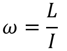
For example, consider a figure skater; when she pulls her arms close to her body, the distribution of her mass around the axis of rotation becomes more concentrated. This reduces her moment of inertia and allows her to spin faster. The below formula shows you how it happens:
Where:
 is the Angular velocity (how fast it spins): Rad/s
 is the Angular momentum: Kg.m2/s
 is the MoI (how mass is spread out): Kg.m2
Since the angular momentum is constant until an external torque is applied, so, the MoI increases as the hands are opened, and as a result, the Angular velocity decreases.
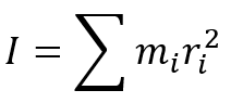
Formula to calculate the MoI:
Where:
 is the Mass of each point.
 is the Distance of each point from the axis.
This quantity can also be defined using the integral:
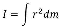
Units:
- Moment of Inertia (I): kg·m²
2. What is a Moment of Area?
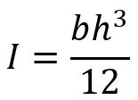
The moment of area also known as the second moment of area determines a structure’s resistance to bending or deformation. It’s a critical factor in construction, ensuring that beams, bridges, and other structures withstand applied loads efficiently. The moment of area about the x-axis in the x-y coordinate is calculated by this equation:

For a rectangular beam of width b and height h, Consider a thin strip of width dx at a distance y from the neutral axis. The moment of area about its centroidal axis (x-axis) is:
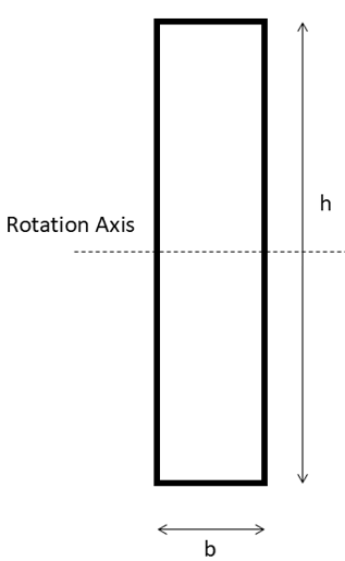
Figure 1: rectangular beam cross-section
The differential moment of area is:
![]()
where dA = bdy.
Integrating over the entire height of the rectangle:
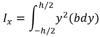
By solving the integral:
Units:
- Moment of Area (I): m4
⚠️ Caution ⚠️: DO NOT confuse moment of inertia with moment of area just because they both use the letter “I”. They are completely different concepts and have different units.
In the next figure for some cross sections, the moment of area is calculated.
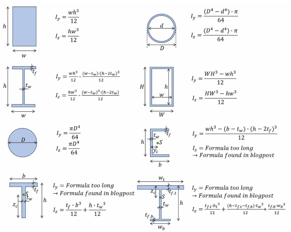
Figure 2: moment of area for different cross sections [Ref]
Both principles, MoI and MoA are essential in designing stable, efficient, and strong engineering structures. Engineers can develop safer, more effective systems, from skyscrapers to spacecraft by mastering these concepts.
3. The Parallel Axis Theorem: Engineering Versatility
The parallel axis theorem, also called the Huygens–Steiner theorem (named after Christiaan Huygens and Jakob Steiner), is a helpful tool for figuring out how an object resists rotation or bending—not just around its center, but around any axis that’s parallel to it.
It works like this:
If you already know the moment of inertia (or second moment of area) around the object’s center of gravity, and you know how far the new axis is from that center, this theorem lets you calculate the moment for the new axis using that distance.
- Moment of Area:
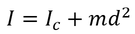
If the axis is not aligned with the centroid, it’s time to rely on the parallel axis theorem to obtain the moment of area:
![]()
-
- IC is the moment of area about the centroidal axis.
- A is cross-sectional area.
- d is the distance between the centroidal axis and the new axis.
- I is the moment of area about the new axis.
- Moment of Inertia:
The parallel axes theorem is not only specific to the moment of area, but can also be used to calculate the MoI about an axis parallel to the axis of mass center. The formula for this MoI is very similar to the moment of area, with a little difference:
-
- IC is the MoI about the center of mass.
- m is the mass of the object.
- d is the distance between the two parallel axes.
- I is the MoI about the new axis.
This theorem is derived from classical mechanics, particularly from the concept of rotational inertia in rigid body dynamics. It is based on the principle that the moment of inertia of an object depends on both its mass distribution and the location of its rotational axis.
Since most engineering structures and components do not always rotate around their centroidal axes, the theorem provides an easy way to extend known inertia values to new rotational axes. The additional term md² accounts for the shift in the axis of rotation.
- Importance of the Parallel Axis Theorem:
- Essential for Beam Design: Used to calculate the correct moment of area when the neutral axis does not align with the centroid.
- Strength Analysis of T-Beams and I-Beams: Structural elements like T-beams and I-beams are made of multiple connected sections. Since their centroidal axes differ from the reference axis, engineers use this theorem to calculate their overall moment of area accurately.
- Application in Robotics and Mechanical Systems: Used to compute the moment of inertia for parts rotating around displaced axes (e.g., robotic arms, crankshafts, linkages), enhancing motion control and stability.
- Crucial for Composite Sections: Helps calculate the overall resistance to bending in composite structures, such as T-beams, where multiple members contribute to the structure’s stiffness.
- Example:
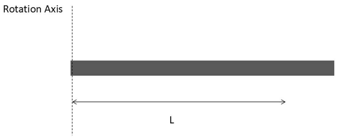
Figure 3: rotational rod about out of center axis
Use the parallel axis theorem to find the MoI of a thin uniform rod when the rod rotated about its end. The MoI when rotated about its center of mass is:
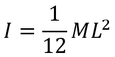
Where:
- M is the rod’s total mass.
- L is the rod’s length.
- Step 1: Determine the distance between the axis of rotation and the parallel axis going through the object’s center of mass. In this case, the axis of rotation has been moved half of the rod’s length from its center of mass or the distance of L/2.
- Step 2: Use the parallel axis theorem to find the MoI of the object about the axis of rotation. Plugging the known MoI for an object about its center of mass, into the parallel axis theorem yields.
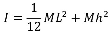
Next, we plug in the proper quantity for h:
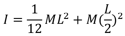
Evaluating the exponent yields:
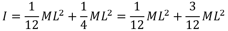
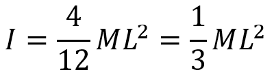
Performing the addition yields the answer:
4. Polar Moment of Inertia
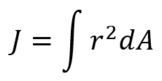
The polar moment of inertia (J), which we will refer it as “PMoI” in this blog, is a geometric property of a cross-section that indicates how the area is distributed around a given axis (typically the center axis of the shaft). It quantifies the resistance of a structural member to torsion.
It is the material’s resistance to torsional (twisting) deformation — related to the shape of a cross-section, not mass. The polar moment of inertia is indeed a kind of second moment of area, just taken about a central (polar) axis, instead of a horizontal or vertical one. Don’t confuse it with the mass moment of inertia, which uses mass elements instead of area.
For common shapes:
-
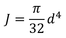
Solid Circular Shaft:
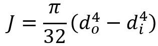
- Hollow Circular Shaft (tube):
Where:
-
d = diameter of the solid shaft
-
do = outer diameter
-
di= inner diameter
Units:
-
SI Units:
meters4 (m4)
But can we use the parallel axes for the PMoI?
Yes, the Parallel Axis Theorem can be applied to the PMoI — but it requires applying it to the two perpendicular planar area moments (Ix and Iy) about the same point. Let’s clear that out.
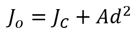
If you know the polar moment of inertia about the centroidal axis of a shape, you can find it about any parallel axis using:
Where:
-
Jo = PMoI about the new axis (not at centroid)
-
JC = PMoI about the centroidal (central) axis
-
A = area of the cross-section
-
d = distance between the centroidal axis and the new axis
But how it works according to what we said earlier?
Remember, the polar moment of inertia is related to both the moments of inertia about the x- and y-axes:
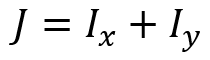
Where:
- Ix is second moment of area about the x-axis
- Iy is the second moment of area about the y-axis
So, applying the parallel axis theorem to each:
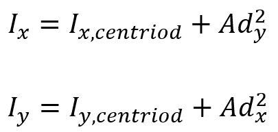
Then:
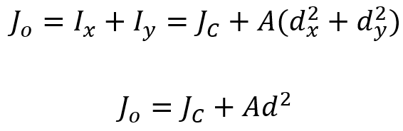
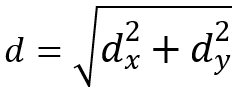
Where:
 is the distance from the centroid to the new axis
- A is the area of the shape
5. Shapes Matter; Hollow Shaft: A Closer Look at Design
Different structural shapes have varying second moments of area and polar moments of inertia, which influence their resistance to bending and torsion, respectively. A good example is the hollow shaft — its shape improves strength while reducing weight.
- Why Are Hollow Shafts Used?
Hollow shafts are widely used in engineering because they offer a high strength-to-weight ratio. Compared to solid shafts, they provide:
- Better resistance to torsion while using less material.
- Lower weight, making them ideal for aerospace and automotive applications.
- Improved energy efficiency by reducing unnecessary mass in rotating systems.
The MoI and MoA for a hollow circular section respectively are given by:
Where:
-
d = diameter of the solid shaft
-
do = outer diameter
-
di= inner diameter
This equation shows that even a small increase in the outer diameter can significantly increase the shaft’s stiffness. This is because both the second moment of area (which governs bending resistance) and the polar moment of inertia (which governs torsional resistance) are proportional to the fourth power of the diameter. As a result, hollow shafts can maintain high stiffness while reducing material usage, making them efficient for resisting bending and twisting forces.
- How Forces Affect a Hollow Shaft
The diagram below illustrates the different forces acting on a hollow shaft and how they influence its MoI and moment of area:
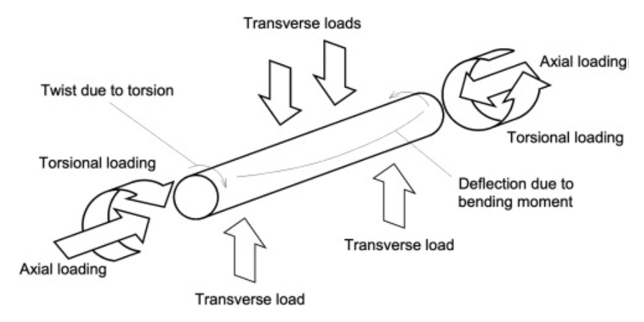
Figure 4: Hollow shaft under different load conditions [Ref]
- Axial Loading: Forces acting along the shaft’s length, affecting stability and buckling resistance.
- Torsional Loading: Twisting forces cause angular deformation, which is resisted by the polar moment of inertia J.
- Transverse Loads & Bending Moments: Forces applied perpendicular to the shaft induce bending moments, resisted by the second moment of area (moment of area).
- Deflection Due to Bending Moment: The deflection (δ) of a beam or shaft under bending is influenced by its moment of area as:
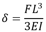
Where:
- F is Applied force (N)
- L is the length of the shaft (m)
- E is Young’s modulus (Pa)
- I is the Moment of area (m4)
- Twist Due to Torsion: The angle of twist θ in a shaft under a torque T is given by:
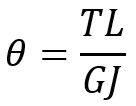
Where:
- T is Applied torque (N·m)
- L is Shaft length (m)
- G is Shear modulus (Pa)
- J is the Polar moment of inertia (m4)
The MoI and MoA defines a structure’s ability to resist torsion and bending forces. Hollow shafts maximize these properties while reducing weight, making them essential in modern mechanical and structural engineering.
6. Conclusion
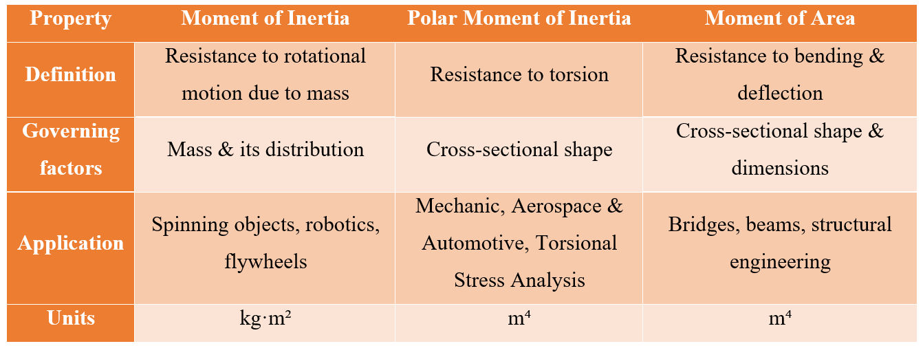
In summary, in the following table, you can observe a comparison between moment of inertia VS polar moment of inertia VS moment of area.
The author of this blog: Abhinav Tanksale.
About the author: Abhinav Tanksale is a CAE Analyst and a passionate blogger who founded My Physics Cafe to help engineers strengthen their grasp on fundamental concepts. Drawing from his own experiences in the industry, he understands the challenges professionals face when the basics aren’t solid. Through his platform, Abhinav delivers clear, practical content designed to build real competence in the technical domain. His philosophy is simple yet powerful: expertise is a natural consequence of consistently applying the basics.
The CAE Assistant is committed to addressing all your CAE needs, and your feedback greatly assists us in achieving this goal. If you have any questions or encounter complications, please feel free to share it with us through our social media accounts including WhatsApp.
Explore our comprehensive Abaqus tutorial page, featuring free PDF guides and detailed videos for all skill levels. Discover both free and premium packages, along with essential information to master Abaqus efficiently. Start your journey with our Abaqus tutorial now!