
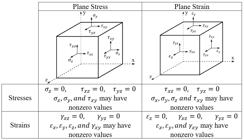
Plane Stress vs Plane Strain: What They Are & When to Use

If you’ve ever looked at a complex 3D model and thought, “There has to be a simpler way,” you’re not alone. That’s where the idea of plane stress vs plane strain comes in! These two clever shortcuts help engineers break down big problems into easier 2D ones. Not sure which one to use or why it matters? Let’s clear it up—simply and quickly.
1. Plane Stress VS Plane Strain
In engineering, we often want to know how materials behave under load. But solving problems in 3D can be slow and complex. That’s where plane stress and plane strain come in. They let us simplify 3D problems into easier 2D ones.
In mechanical engineering, plane stress and plane strain are two fundamental concepts used to simplify the analysis of stress and deformation in materials. Plane stress applies to thin objects where stress in one dimension (like thickness) is negligible, often seen in thin plates under load. Plane strain, on the other hand, is used for long structures where strain in one direction is minimal, such as in long walls or dams. Understanding these concepts helps engineers predict material behavior under various loading conditions effectively.
These two concepts help engineers predict how things stretch, compress, or deform—without doing unnecessary math.
-
Plane stress happens in thin objects where forces act mostly in two directions. The stress in the thickness direction is so small we can ignore it, often seen in thin plates under load.
- ✔️ Only stresses in X and Y directions matter
- ❌ Stress in Z direction ≈ 0
-
Plane strain shows up in thick or long structures, where one direction doesn’t stretch or shrink at all, such as in long walls or dams.
- ✔️ Strain in Z direction = 0
- ❌ It’s not allowed to deform in the long direction
 Plane Stress VS Plane Strain
2. Why 2D Modeling? | Plane Stress and Plane Strain
Two-dimensional (2D) modeling is a smart and efficient method in structural and mechanical analysis. It works best when one dimension of a structure is either very small or very large compared to the others.
By assuming a constant or negligible variation along the thickness direction, 2D analysis significantly reduces computational cost without sacrificing much accuracy. This makes it possible to simulate large structures, like bridges or pressure vessels, using less time and memory than full 3D models.
Moreover, 2D assumptions allow engineers to focus on capturing essential behaviors, such as stress concentrations, load paths, and deformation patterns, while avoiding unnecessary complexity. Especially during early design stages or feasibility studies, 2D modeling accelerates decision-making by quickly identifying critical issues. When properly applied, plane stress and plane strain approximations yield results that are not only faster to compute but also highly reliable.
In both cases (Plane stress and plane strain), we reduce the problem to two dimensions, typically the x-y plane. This reduces the number of equations to solve, simplifies boundary conditions, and accelerates computation without major sacrifices in accuracy.
Advantages of 2D Modeling in Plane Stress and Plane Strain:
- Time Savings: A 2D simulation can be solved in a fraction of the time needed for a 3D model, making it ideal for design iterations, preliminary studies, or concept validation.
- Lower Resource Requirements: 2D models consume far less memory and processing power, allowing complex simulations to be run even on modest computers.
- Clearer Insights: By focusing on a plane, engineers can more easily visualize stress distributions, deformation patterns, crack paths, and strain localizations. In general, the results are more understandable if you use 2D modeling.
3. What is Plane Stress?
Plane stress occurs when the stress across one dimension (usually the thickness) is negligible compared to the stresses in the other two dimensions. This is often seen in thin plates subjected to forces perpendicular to the plane. For example, a thin metal sheet is subjected to tension in its plane. The stresses in the thickness direction are negligible compared to the in-plane stresses.
- Stress Tensor for Plane Stress:
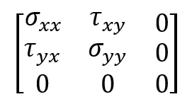
As you can see, there are no stress components perpendicular to the plane (z direction). There are only normal and shear stresses in the in-plane direction (x-y plane). The figure below shows in-plane stresses.
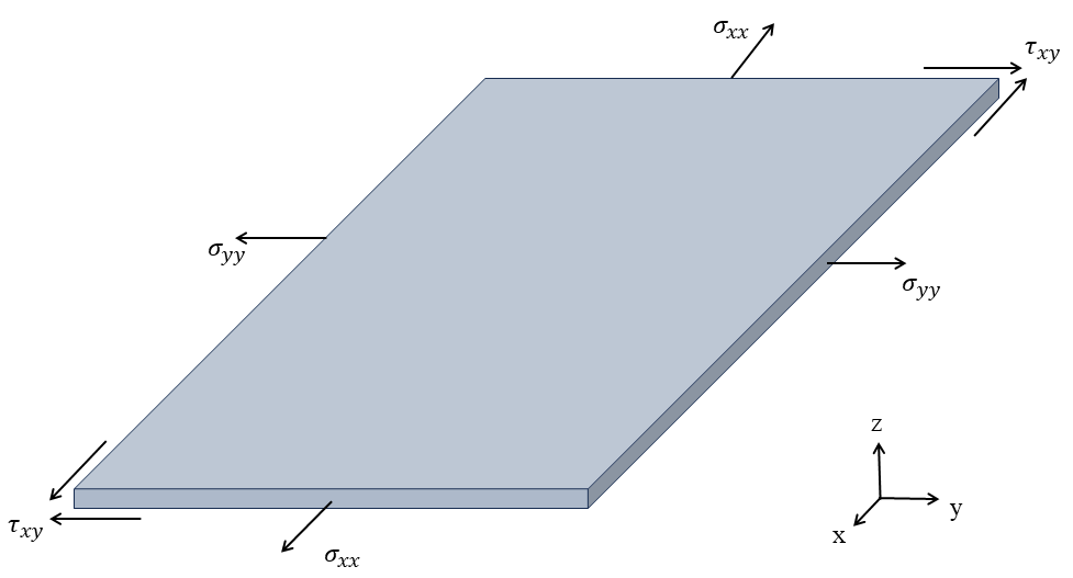
Figure 1: Plane stresses in the x-y plane
- Formulas and Relations (Constitutive Model):
Plane stress conditions arise when a structure is very thin compared to its other dimensions, such that out-of-plane stresses are negligible, so:

The constitutive relations between stress and strain (based on linear elasticity) are:
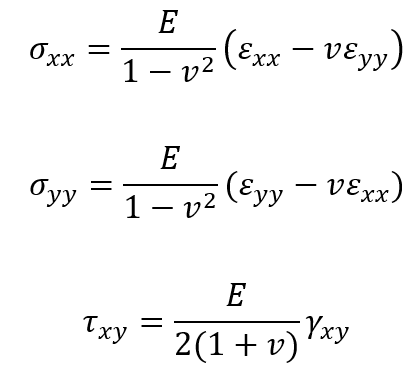
where:
- E is Young’s modulus
- v is Poisson’s ratio
 and
and  are normal strains
 is engineering shear strain
In plane stress, deformations are allowed freely along the thickness, meaning no constraint inhibits out-of-plane expansion or contraction.
4. What is Plane Strain?
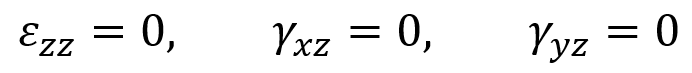
Plane strain refers to a condition in which deformation occurs only in two dimensions while the strain in the third dimension is negligible or zero. This is common in long structures where the length dimension is much greater than the other two.
For example, a long concrete dam is subjected to loading along its height and width. In these cases, the strain across the length of the structure is assumed to be zero, and only the strains in the other two dimensions (height and width) are considered.
- Strain Tensor for Plane Strain:
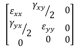
The figure below shows a schematic figure in plane strain.
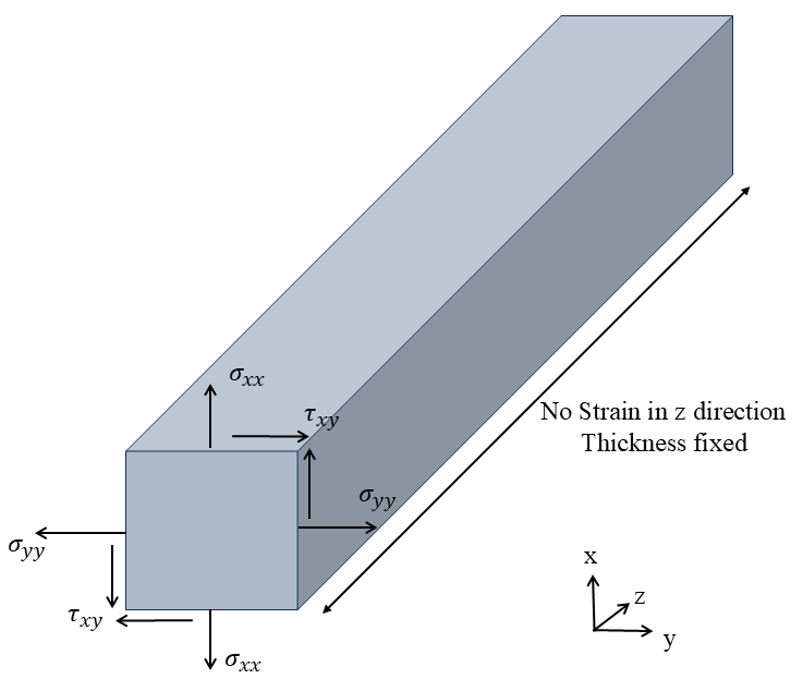
Figure 2: Plane strain schematic
- Formulas and Relations (Constitutive Model):
Plane strain conditions occur when the structure is extremely long or restrained in one direction, preventing any deformation along that axis. Based on the strain matrix, the assumptions are:
So, the stress-strain relationships for plane strain are:
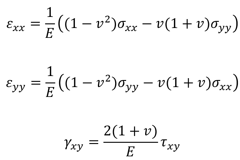
Where:
- E is Young’s modulus
- v is Poisson’s ratio
 and
and  are normal stresses in the x and y directions.
- shear stress
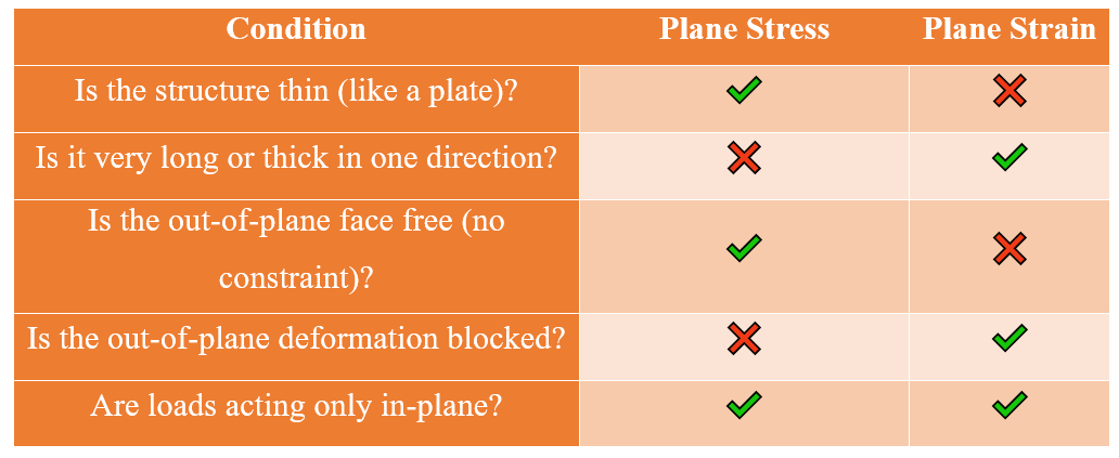
5. Which one should we choose? Plane stress or plane strain
Selecting between plane stress and plane strain isn’t just about picking a simulation method — it’s about matching the mathematical model to the real physical behavior of your structure. The choice depends mainly on geometry, boundary conditions, and loading direction.
- Use Plane Stress When:
- The thickness is very small compared to its length and width (typically less than 1/10).
- The loads lie in the plane of the structure.
- There are no constraints in the out-of-plane direction (the structure is free to deform through the thickness).
Examples:
- Thin metal or plastic sheets
- Car body parts
- Thin composite laminates
- Use Plane Strain When:
- The structure is very long or thick in one direction, and you assume no deformation along that axis.
- The out-of-plane strain is essentially zero due to physical constraints or symmetry.
- The body experiences uniform behavior in the long direction.
Typical examples:
- Long tunnels or pipelines buried underground
- Earth dams
- Cross-sections of extrusion dies
Sometimes, it’s not easy to decide between plane stress and plane strain. The structure might fall somewhere in between. For example:
- If your part is not very thin or very thick (for example, a plate with medium thickness), the outer layers might behave like plane stress, while the center behaves more like plane strain.
- If your part has holes, notches, or sharp corners, the stress around those areas can become three-dimensional, even if the rest of the structure is 2D.
If you’re unsure which option fits best, avoid guessing. Run both plane stress and plane strain simulations to see the range of possible stress or strain values. This helps you estimate the lower and upper bounds. For higher accuracy, you can switch to a full 3D model. Below, there is a table that reviews conditions for selecting Plane stress and strain quickly.
 Conditions for selecting the Plane stress and strain method
6. What is stress?
Stress is the force or pressure that a material feels when something pushes or pulls on it. Imagine squeezing a rubber ball or stretching a rubber band both are under stress. The more you push, pull, or twist something, the more stress it feels. If the stress becomes too much, the material can change shape or even break. Stress helps engineers understand how much weight or pressure a material can handle before it starts to get damaged.
Stress in the context of the mechanics of materials is defined as the internal force per unit area within a material.
6.1. Real Examples of Stress
- Tensile Stress: The tension in a cable supporting a suspended bridge
- Compressive Stress: The compression in a concrete column supporting a building
- Shear Stress: When a material is subjected to a force that causes sliding, such as in scissors cutting paper.
- Torsion Stress: The torsion in a drive shaft of a car
- Bending Stress: The bending stress in an arch bridge
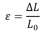
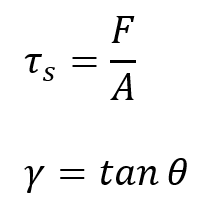
6.2. Stress Formula
The formula for stress (![]() ) is:
) is:
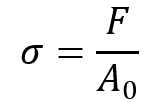
Where:
 is the stress,
- F is the applied force,
- A is the original cross-sectional area over which the force is applied.
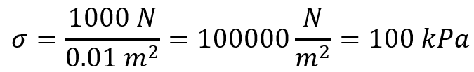
Example: If a rod with a cross-sectional area of 0.01 m² is subjected to a tensile force of 1000 N, the stress is:
6.3. Stress Unit
The unit of stress in the International System of Units (SI) is the Pascal (Pa), which is equivalent to one Newton per square meter (N/m²). Other units of stress include:
- Kilopascal (kPa): 1 kPa=1000 Pa
- Megapascal (MPa): 1 MPa=1,000,000 Pa
- Pounds per square inch (psi): Commonly used in the United States, where 1 psi=6894.76 Pa
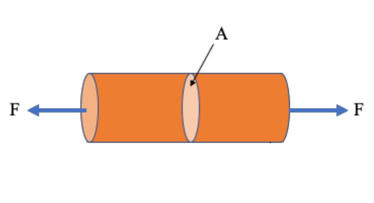
Figure 3: Stress concept [reference]
|
If you need deep training, our Abaqus Course offerings have you covered. Visit our Abaqus course today to find the perfect course for your needs and take your Abaqus knowledge to the next level! |
 |
In this Abaqus training package for beginners, which is designed for FEM Simulation students in mechanical engineering, various examples in the most widely used fields are presented:
|
7. What is strain?
Strain is a measure of deformation representing the displacement between particles in the material body. It quantifies how much a material reshape under forces. Imagine a rod getting stretched under tension. Strain tells you by what fraction its length increased compared to its initial length. Strain is a dimensionless quantity as it represents the ratio of the change in length to the original length.
7.1. Real Examples of Strain
- Tensile Strain: When a rubber band is stretched, the length increases compared to its original length.
- Compressive Strain: When a sponge is squeezed, its length decreases compared to its original length.
- Shear Strain: When a stack of paper is pushed sideways, the layers shift relative to each other.
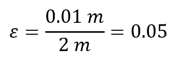
7.2. Strain Formula
The formula for linear strain (![]() ) is:
) is:
Where:
 is the linear strain,
 is the change in length,
 is the original length.
Example: If a steel bar originally 2 meters long stretches by 0.01 meters under a load, the strain is:
7.3. Strain Unit
Strain is a dimensionless quantity because it is a ratio of two lengths. Therefore, it does not have any units. It is often expressed as a percentage or a fraction.
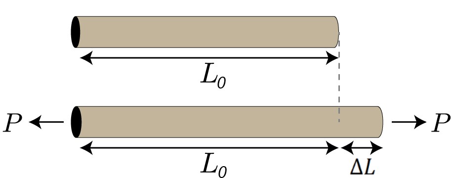
Figure 4: Strain concept [reference]
 |
⭐⭐⭐ Free Abaqus Course | ⏰10 hours Video 👩🎓+1000 Students ♾️ Lifetime Access
✅ Module by Module Training ✅ Standard/Explicit Analyses Tutorial ✅ Subroutines (UMAT) Training … ✅ Python Scripting Lesson & Examples |
8. What are engineering and true stress and strain?
Engineering Stress and Strain and True Stress and Strain are two different ways of measuring the stress and strain in a material.
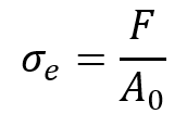
8.1. Engineering Stress and Strain
- Engineering Stress (
 ): Engineering stress is calculated by dividing the applied load (F) by the original cross-sectional area (
 ) of the material:
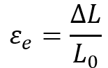
- Engineering Strain (
 ) Engineering strain is calculated by dividing the change in length (
 ) by the original length (
 ):
):
8.2. True Stress and Strain
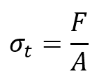
- True Stress (): True stress is calculated by dividing the applied load (F) by the instantaneous cross-sectional area (A) of the material:
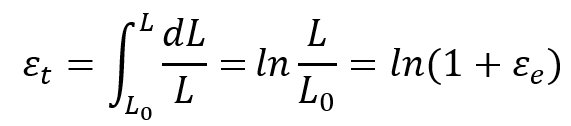
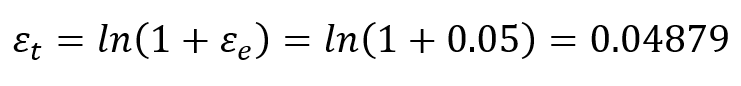
True Strain ( ![]() ): True strain is calculated by integrating the incremental change in length over the original length:
): True strain is calculated by integrating the incremental change in length over the original length:
8.3. Differences between Engineering and True Stress and Strain
Engineering stress and strain are sufficient for many engineering problems, especially in the initial linear elastic region. True stress and strain become more important for highly deformable materials (plastics, metals undergoing large strains) where necking (reduction in area) occurs.
- Engineering Stress and Strain are simpler to calculate and are often used in the initial design and analysis of materials. They are based on the original dimensions of the material and do not account for the changes in dimensions that occur during deformation.
- True Stress and Strain provide a more accurate representation of the material’s behavior, especially at higher strains. They account for the actual changes in the dimensions of the material as it deforms.
8.4. Example: Tensile Test
Imagine a round metal bar being stretched in a tensile test. Initially, the engineering and true stress and strain will be very close. However, as the bar necks (becomes thinner in a specific region), the true stress will increase due to the reduced area, while the engineering stress will decrease based on the constant original area.
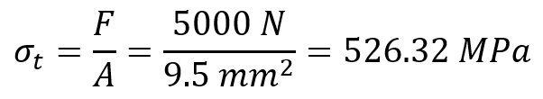
- Engineering Stress and Strain: Suppose a metal rod with an original cross-sectional area of 10 mm2 and an original length of 100 mm is stretched by 5 mm under a load of 5000:
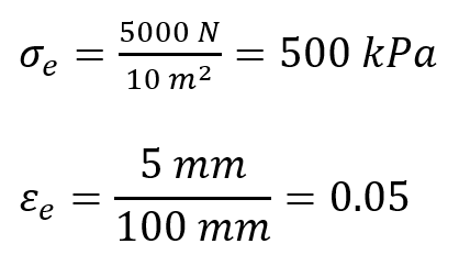
- True Stress and Strain: Assume the cross-sectional area at the stretched length is 9.5 mm2 due to necking.
In the third lesson of Abaqus for beginners package, there is a simple example of a beam that would help you to simulate concentrated load on it and do a stress analysis to have the stress distribution one the beam.
9. What are types of stress and strain?
Stress and strain can be categorized into several types based on the nature of the forces and deformations involved. Below are detailed explanations of different types of stress and strain, along with examples and formulations.
9.1. Normal Stress and Strain
- Normal Stress is the stress that occurs perpendicular to the surface of the material. It can be tensile (stretching) or compressive (squeezing).
- Normal Strain is the deformation per unit length in the direction of the applied load.
In the previous sections, formulas and examples for this type of stress and strain were presented.
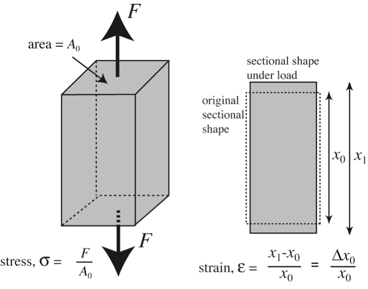
Figure 5: Normal stress and strain [reference]
Learn the normal stress with a practical example: 3D truss modeling in Abaqus.
9.2. Bending Stress and Strain
- Bending Stress occurs when a moment or bending force is applied to a member of structure like beam, causing it to bend.
- Bending Strain is the deformation resulting from the bending moment.
Formulation:
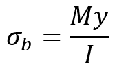
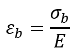
Where:
- M is the bending moment,
- y is the distance from the neutral axis,
- I is the moment of inertia,
- E is the modulus of elasticity.
Example: Let’s consider a beam (like a metal rod) with a length of 2 meters, supported at both ends. If you apply a force of 500 Newtons directly in the middle of the beam, it will bend downwards. To calculate the bending stress, let’s assume the beam has a rectangular cross-section with a width of 0.1 meters and a height of 0.05 meters.
- Bending Moment:

- Distance from the neutral axis (half the height): y=0.025 m
- Moment of inertia:

- Bending Stress:

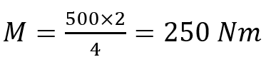
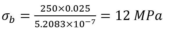
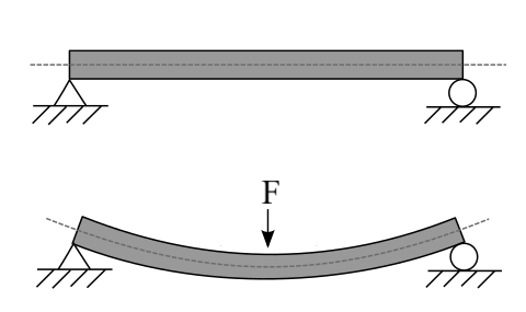
Figure 6: Example of bending [reference]
9.3. Shear Stress and Strain
- Shear Stress (
 ) occurs when forces are applied parallel to the surface of the material.
 - Shear Strain (
 ) is the angular deformation resulting from the applied shear stress.
Formulation:
Where:
 is the angle of deformation.
Example: A bolt with a cross-sectional area of 20 mm2 is subjected to a shear force of 1000 N. The angle of deformation is also equal to ![]() .
.
- Shear Stress:
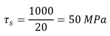
- Shear Strain: base on formula, shear strain is equal to
 .
.
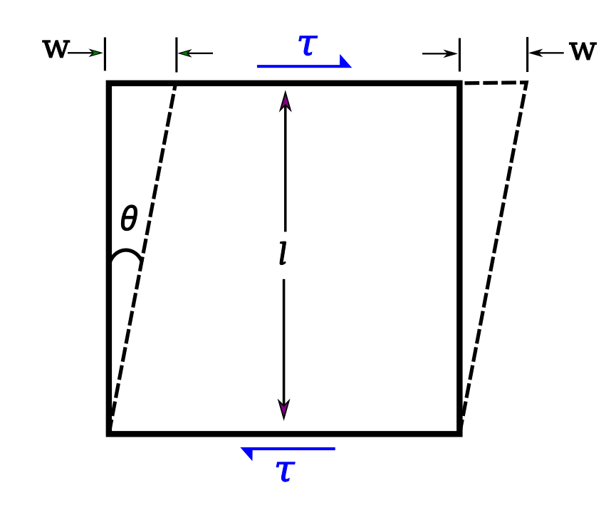
Figure 7: Shearing [reference]
9.4. Torsional Stress and Strain
- Torsional Stress () occurs when a material is subjected to a twisting moment or torque.
- Torsional Strain () is the angular deformation resulting from the applied torque.
Formulation:
Where:
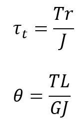
- T is the applied torque,
- r is the radius of the shaft,
- J is the polar moment of inertia,
- G is the modulus of rigidity,
- θ is the angle of twist.
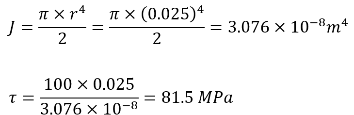
Example: Let’s say you have a solid metal rod with a length of 1 meter and a circular cross-section with a diameter of 0.05 meters. You twist one end of the rod while the other end is fixed. The twisting force you apply is called torque. If you apply a torque of 100 Nm to the rod, you can calculate the torsional stress using the formula (The modulus of rigidity for the material is equal to ![]() ):
):
- Torsional Stress:
- Angle of Twist:
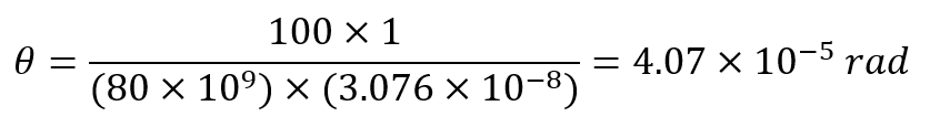
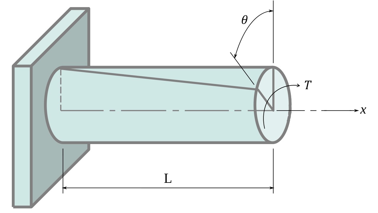
Figure 8: Torsion [refernce]
9.5. Thermal Stress and Strain
- Thermal Stress (
 ) occurs when a material is subjected to a change in temperature, causing it to expand or contract.
 - Thermal Strain () is the deformation resulting from the change in temperature.
Formulation:
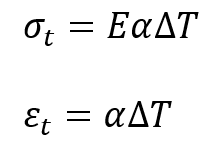
Where:
- E is the modulus of elasticity,
- α is the coefficient of thermal expansion,
- ΔT is the change in temperature.
Example: A steel rod with a coefficient of thermal expansion of ![]() and a modulus of elasticity of 200 GPa is heated from 20
and a modulus of elasticity of 200 GPa is heated from 20![]() to 100
to 100![]() .
.
- Thermal Strain:
![]()
- Thermal Stress (assuming no deformation is allowed):
![]()
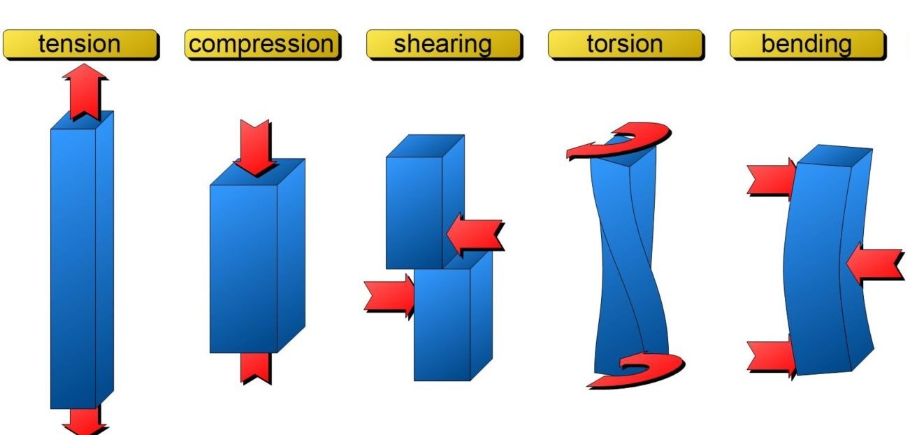
Figure 8: All types of stress[reference]
Now you have learned types of stress and strain, right? But I’m sure you have heard of Principal stress and strain, and also Mohr’s circle. What are these? what is the difference between them? You can learn all of it in this article: “What is Von Mises Stress? | Mohr’s Circle and Principal Stress and Strain“
Read more: you can read about stress and strain relationship and all about stress strain curve in our other blog.
Question: What are the units of stress and strain in Abaqus? Get the answer in: “Used Units in Abaqus | Abaqus units“
10. Conclusion
Explore our comprehensive Abaqus tutorial page, featuring free PDF guides and detailed videos for all skill levels. Discover both free and premium packages, along with essential information to master Abaqus efficiently. Start your journey with our Abaqus tutorial now!
The CAE Assistant is committed to addressing all your CAE needs, and your feedback greatly assists us in achieving this goal. If you have any questions or encounter complications, please feel free to share it with us through our social media accounts including WhatsApp.