
Shear Force & Bending Moment Full Guide + Diagrams explained
Ever noticed how bridges carry tons of weight without collapsing? Or how buildings stand firm against both people and weather? It’s not magic—it’s physics. And two of the most important concepts behind this stability are shear force and bending moment.
To grasp shear force, think about cutting a piece of paper with scissors. The opposing forces cause the paper to shear. Similarly, in a beam, shear force represents the internal resistance to external loads acting perpendicular to its length. Bending moments, on the other hand, describe how forces create rotational effects, causing beams to bend. These concepts help engineers predict stress distribution and design structures that withstand applied loads.
In this blog, we will explain shear force, shear stress, and bending moments. We will discuss their mathematical representations, sign conventions, and how to visualize them using shear force and bending moment diagrams. Additionally, we will analyze practical examples to help you understand how these forces affect different structures.
1. What is Shear force?
Shear force is the internal force in a structure or material that resists the sliding of one part over another due to external loads. It can also refer to external forces applied in a way that induces shearing.
Example:
- Internal shear force: When analyzing beams in structural analysis, we calculate internal shear forces to understand internal stress distributions.
- External shear force: When two opposite, parallel forces are applied on a plate (like a punch press), they are shear forces externally applied.
Mathematically, shear force at any section is:
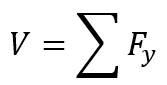
Where:
- Fy represents vertical forces.
- V is shear force.
Units:
Shear force (V): Newton
2. What is Shear Stress (Shear)?
- Shear (Shear Stress): shear itself is not a force—it’s a mechanical phenomenon or type of deformation. It describes how material layers slide past each other when subjected to opposing forces. Shear stress acts parallel to the surface of a material, causing one part of the material to slide past the other. A simple example is cutting a piece of paper with scissors and the paper experiences shear stress.
The formula to calculate the shear stress is:
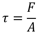
Where:
 is shear stress (how much force is causing the sliding effect)
- A is a cross-sectional area (the area where the force is applied)
- F is applied force (force acting on the object)
Units:
Shear stress (![]() ): Pascal
): Pascal
3. What is Bending Moment?
The bending moment is the rotational effect of a force acting at a distance, which causes the beam to bend. It is the product of force and the perpendicular distance from a reference point to the line of action of the force. For example, imagine a cantilever beam fixed at one end and loaded at the other. The applied force creates a bending moment at the fixed end, trying to rotate or bend the beam.
Mathematically:
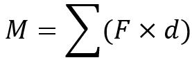
- Where d is the distance from the section.
- M is bending moment.
4. Sign Conventions of Shear force and Bending moment
- Shear Force: Positive shear force if it induces a clockwise rotation to the beam element. In contrast, it is regarded as negative when induced counterclockwise rotation is evaluated.
- Bending Moment: Positive Bending moment if it produces tension in the bottom fibers and compression at the top fibers in the beam. Negative if it does exactly the opposite.
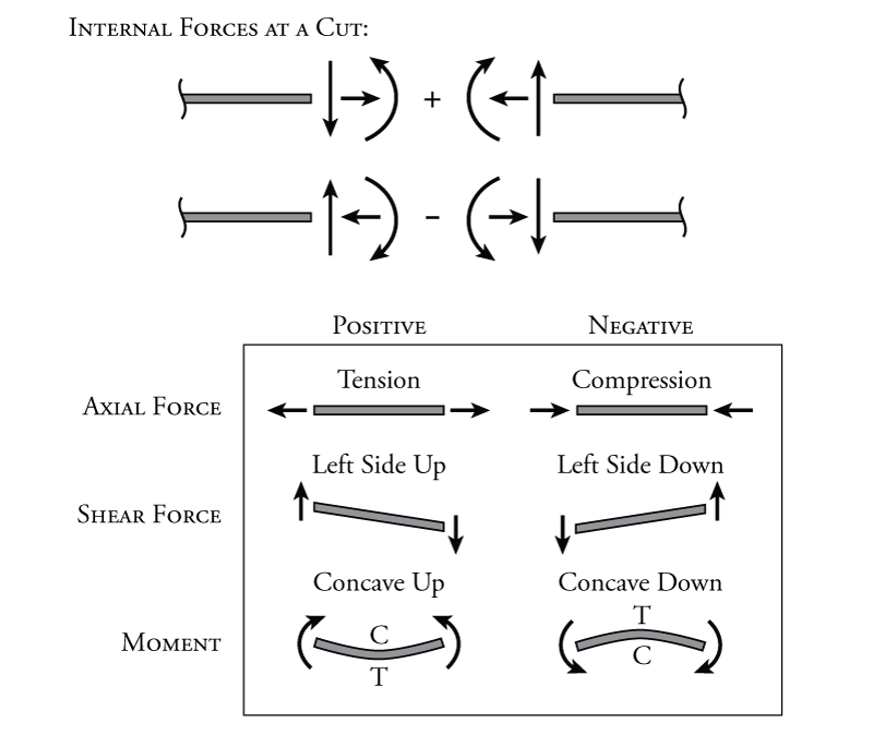
Figure 1: shear force and bending moment sign Conventions
5. shear force and bending moment diagram
After understanding the fundamental definitions of shear force and bending moment, let’s analyze how they are visually represented in the form of diagrams. The image below illustrates the shear force diagram (SFD) and bending moment diagram (BMD) for a cantilever beam subjected to a point load (P) at its free end.
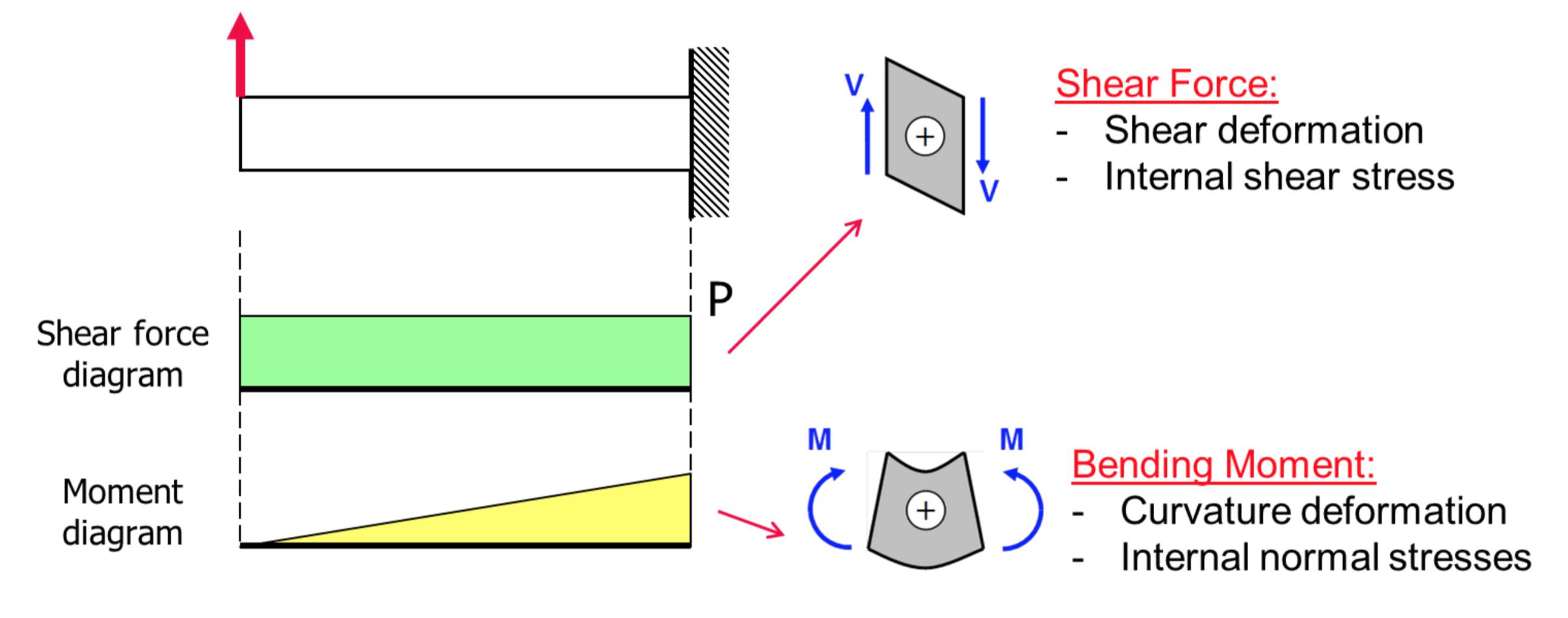
Figure 2: Bending moment diagram and shear force diagram for a beam [Ref]
- Shear Force Diagram (SFD):
The shear force (V) at any section of the beam is the sum of vertical forces acting to the left or right of that section. The shear force diagram (SFD) in the image is a horizontal green rectangle. In this case, since there is only one point load (P) at the free end, the shear force remains constant throughout the beam. The shear force at every point is equal to P (positive sign due to upward force).
Mathematical Representation:
![]()
Thus, the shear force diagram appears as a horizontal rectangle indicating a constant value throughout the length of the beam.
- Bending Moment Diagram (BMD):
The bending moment (M) at any section of the beam is the product of the force (P) and the perpendicular distance (x) from the free end. The moment increases linearly as we move towards the fixed support, where the maximum bending moment occurs.
Mathematical Representation:
![]()
At the free end (x=0), the moment is zero.
At the fixed end (x=L), the moment is maximum and given by:
![]()
The bending moment diagram appears as a triangular shape, showing a linear variation from 0 at the free end to PL at the fixed support.
6. Distribution of Shear Stress and Bending Stress
Once we know the shear forces and bending moments in a beam, the next question is—how do those internal forces translate into actual stresses within the material?
Let’s start with bending stress. When a beam bends, the material on one side stretches (tension) while the other side compresses. The stress isn’t uniform—it varies linearly across the height of the beam’s cross-section. That’s why, in an I-beam, the flanges carry most of the bending stress.
Now, shear stress is a bit different. It peaks at the neutral axis and tapers off toward the top and bottom surfaces. Most of this stress is handled by the web of the I-beam.
So, not all parts of a beam handle stress the same way. The way these internal forces spread through the beam’s cross-section affects everything from material choice to cross-section shape.
We can express these stress distributions mathematically, and we’ll walk through the key equations below.
Before diving into how stresses are distributed across a beam’s cross-section, it’s worth quickly revisiting why they occur in the first place.
At the core of structural analysis are two things: equilibrium and material behavior. As engineers, we know every segment of a beam must satisfy the basic conditions of static equilibrium:
Equilibrium: Any segment of a beam must satisfy the conditions of static equilibrium:
 (no net horizontal force).
 (no net vertical force).
 (no net moment about any point).
These conditions ensure the structure stays balanced. But the real-world challenge isn’t just about balance—it’s about how the material inside the beam resists these loads. That’s where internal forces like shear and bending come into play—and where things start to get interesting.
So, again, not all parts of a cross-section carry stress the same way. The internal stress distribution is what drives most structural design choices.
Let’s break it down into two parts: bending stress and shear stress.
6.1. Bending Stress Distribution
Bending moments cause bending stresses.
When a beam bends, the material fibers on opposite sides of the neutral axis behave differently:
-
The top fibers compress
-
The bottom fibers stretch
-
And right in the middle, at the neutral axis, there’s no bending stress
This creates a linear stress distribution: zero at the center and maximum at the top and bottom surfaces. That’s why in I-beams, we beef up the flanges—they take most of the bending load.
The bending stress is calculated as:
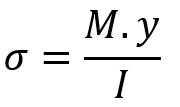
Where:
-
= bending stress (Pa or N/m²)
-
M = bending moment at the section (Nm)
-
y = distance from the neutral axis (m)
-
I = moment of inertia of the cross-section (m⁴)
6.2. Shear Stress Distribution
Shear force leads to shear stresses.
Shear stress follows a different pattern. It’s maximum at the neutral axis and tapers to zero at the top and bottom of the beam. This creates a parabolic distribution in rectangular beams, and it’s especially important in I-beams where the web (vertical part) carries most of the shear.
Here’s the shear stress formula:
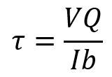
Where:
-
= shear stress at a given point (Pa or N/m²)
-
V = shear force (N)
-
Q = first moment of area above the point of interest (m³)
-
I = moment of inertia (m⁴)
-
b = width of the section at that point (m)
6.3. Why Stress Distribution Matters
Understanding how stress distributes through a beam isn’t just a theory exercise—it’s a design tool. It tells us:
-
Where to add material to resist bending (the flanges)
-
Where to reinforce for shear (the web)
-
And where failures are most likely to begin
When you’re evaluating a design—or diagnosing a failure—these stress patterns usually tell the full story.
6.4. Mathematical Approach
In three steps we can calculate forces and stresses in the beam section:
Step 1: Find Support Reactions:
To start, we calculate the reactions at the supports. By using equilibrium equations
Step 2: Calculate Shear Force:
To find the shear force at any point along the beam:
- For a Concentrated Load, the shear force is equal to the concentrated force.
- For a uniformed distributed load (UDL), the shear force is equal to the summation of the concentrated support force and the concentrated force resulting from the conversion of the extended force
Step 3: Calculate Bending Moment (M):
The bending moment at any point is obtained by integrating the shear force
These calculations help us draw the Shear Force and bending moment Diagrams.
7. Practical Example: Beam Calculation
In the following example, we are going to calculate shear forces and bending moments for beam that see in next figure. Finally, we will determine shear force and bending moment diagrams for beam.
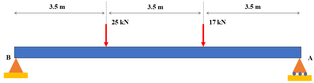
Figure 3: simply supported beam under to concentrated forces
First of all, we should draw free body diagram. The B support is pinned so it can carry both vertical and horizontal forces but A support is roller support and just can carry vertical load. The following figure shows free body diagram.
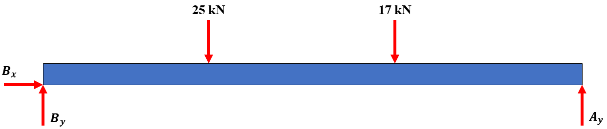
Figure 4: Beam free body diagram
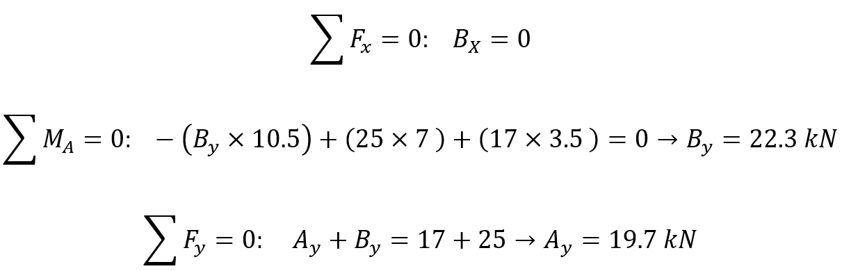
To calculate supports reactions, we should use equilibrium equations. Because there is no force in x direction so ![]() is equal to zero:
is equal to zero:
After calculating supports reactions, for defining shear forces and bending moment at any segment we have to make some section between any forces. First, we start by left side of the beam:
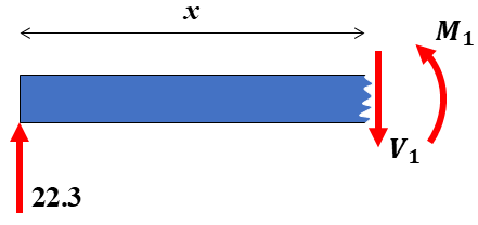
Figure 5: Free body diagram for first cut
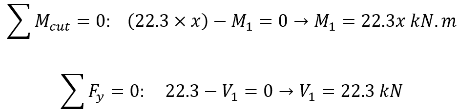
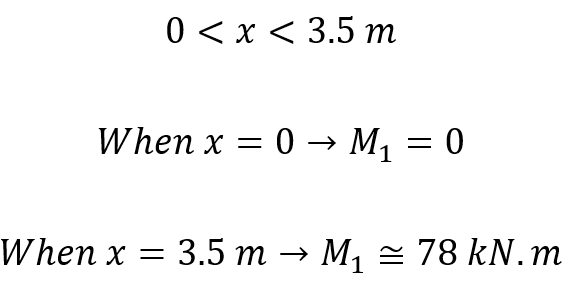
If x is the distance of an arbitrary section from the pinned end of the beam, so bending moment for this distance is determined as follows:
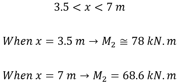
Now it’s turn to repeat these calculations for next cut (between two concentrated forces):
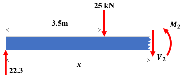
Figure 6: Free body diagram for second cut
For this cut, just like first one we should use equilibrium equations:
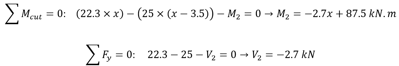
For this distance x is between 3.5mm to 7mm:
Now by information obtained, we can draw shear force and bending moment diagram. Pay attention because the roller support can’t tolerate bending moment, so we don’t need to calculate bending moment between 17kN force and roller support. In this distance bending moment decrease to zero.
As you can see in Figure 8, wherever a concentrated force is applied to the beam, the shear force increases or decreases in a step function way.
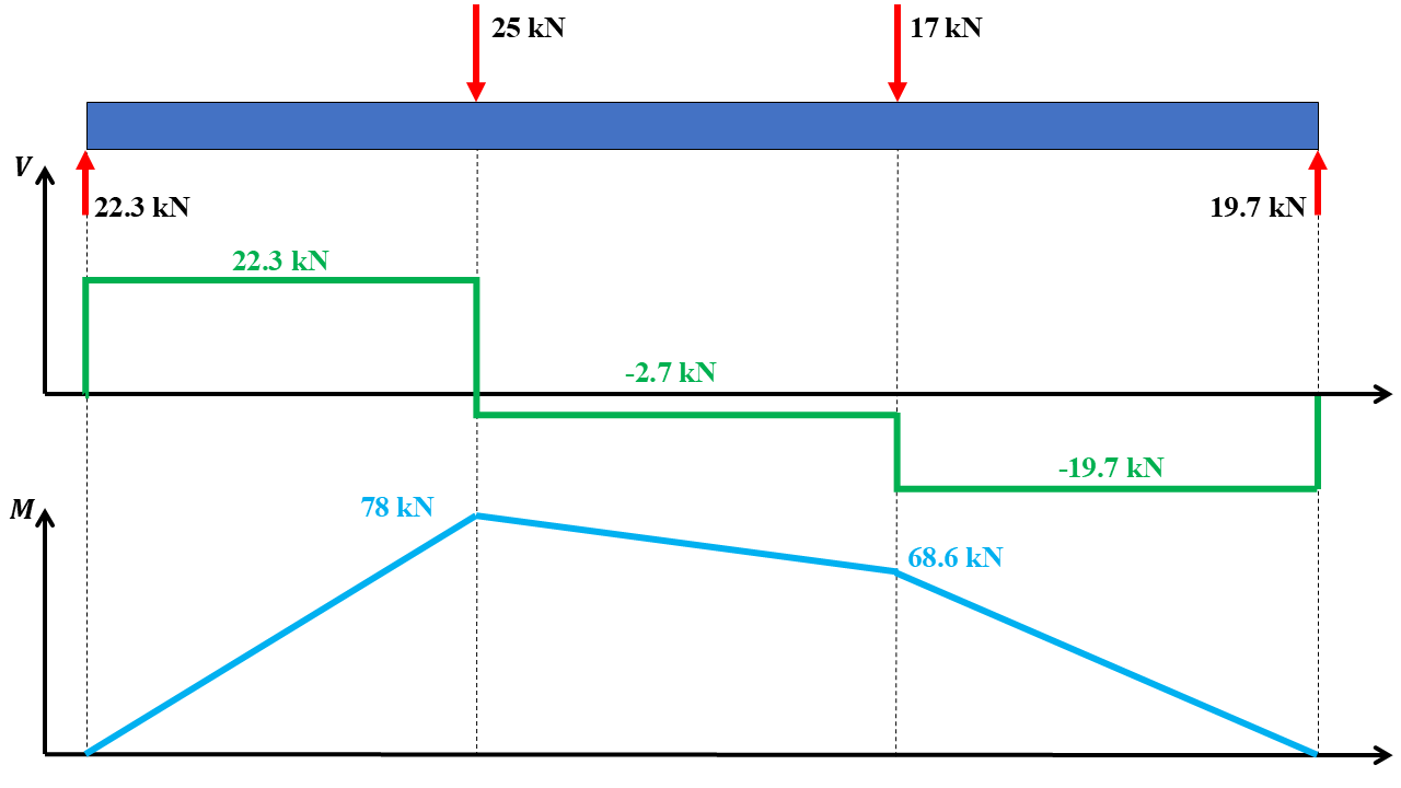
Figure 7: shear force and bending moment diagrams
8. Conclusion
This article covered shear force, shear stress, and bending moments, which are essential concepts in structural analysis. Understanding these forces helps engineers design safe and efficient structures by predicting how materials respond under different loads.
We began by defining shear stress, shear force, and bending moments, explaining their significance in engineering. Then, we discussed shear force and bending moment diagrams, showing how these forces vary along a beam. The article also covered sign conventions, which help in correctly analyzing these forces. Additionally, we examined the distribution of shear and bending stress within a beam, highlighting how stress varies across different sections. Finally, we explored mathematical approaches and practical examples to apply these concepts in real-world scenarios.
From this discussion, we learned that shear force and bending moment analysis is crucial for structural stability. Engineers use these principles to calculate forces, design safer structures, and ensure materials can withstand applied loads.
The author of this blog: Abhinav Tanksale.
About the author: Abhinav Tanksale is a CAE Analyst and a passionate blogger who founded My Physics Cafe to help engineers strengthen their grasp on fundamental concepts. Drawing from his own experiences in the industry, he understands the challenges professionals face when the basics aren’t solid. Through his platform, Abhinav delivers clear, practical content designed to build real competence in the technical domain. His philosophy is simple yet powerful: expertise is a natural consequence of consistently applying the basics.