
Truss Analysis Full Guide | Theory + Simulation Tutorial
Trusses are structural systems made of straight members joined at nodes. Each member carries only axial loads—tension or compression. Truss analysis helps engineers predict how these members behave under various forces. This is key for safe designs in bridges, roofs, towers, and other load-bearing structures.
Engineers use two main approaches to truss analysis: the Method of Joints and the Method of Sections. These methods rely on equilibrium equations and are useful for hand calculations. However, for larger or more complex systems, truss simulation using the Finite Element Method (FEM) is more efficient. Abaqus is a powerful FEM tool that models truss behavior in detail.
This blog explains how truss elements work and how to check their stability. It also covers the basics of analysis methods and how to use Abaqus to simulate a truss. You’ll learn a full modeling workflow—from setup to result review—and get tips for common issues. Finally, a case study compares analytical and simulation results to show how accurate FEM-based truss analysis can be.
1. What is Truss (Elements & Stability)? Fundamentals and Applications
First, it’s essential to understand what makes truss structures unique; but let’s make a simple definition of it: A truss is a structure made of straight members connected at joints, designed so that each member only carries tension or compression — no bending.
In common terminology, a truss refers to a rigid framework composed of a series of straight components. However, within the realms of engineering and material strength, it possesses a more precise definition – in these fields, a truss is characterized as a structure consisting of members that exclusively bear axial loads.
Now, let’s dive deeper to understand it better starting with truss elements.
1.1. Truss Elements
Truss elements are straight members connected at joints, carrying only axial force—tension or compression.
Members of a structure can be deemed to solely carry axial loads if the following conditions are met:
Assumption 1: The joints of the structure behave like pinned connections
Assumption 2: Loads are only applied at the joints of the structure
When these conditions are applicable, the truss members are not subjected to any bending moments – they solely endure axial loads. Consequently, each member of a truss must be either under tension or compression.
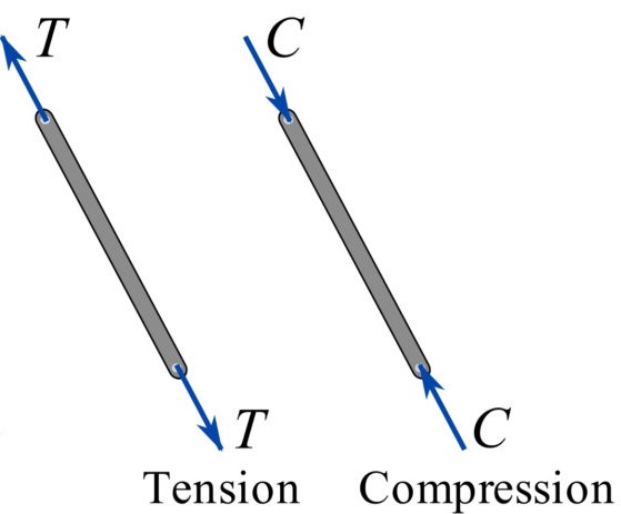
Figure 1: Truss under tension or compression
1.2. Truss VS Frame
The exclusive nature of axial loads on truss members simplifies the analysis of trusses significantly compared to the analysis of frames, where members may experience both bending moments and axial loads. The truss and frame comparison are presented in the following table.
| Feature | Truss | Frame |
| Load Resistance | Primarily axial (tension and compression) | Axial, shear, and bending |
| Joints | Typically pinned (allowing rotation) | Can be pinned or rigid (restricting rotation) |
| Bending Moments | Generally, not designed to resist bending moments | Can resist bending moments |
| Typical Applications | Roof structures, bridges, long-span structures | Buildings, machine frames, general structures |
| Member Connections | Typically connected at joints | Members can be continuous or connected at joints |
| Flexibility | Can be more flexible in resisting transverse loads | More rigid and can resist transverse loads better |
| Weight | Can be lighter for the same load capacity | Can be heavier than a truss for the same load capacity |
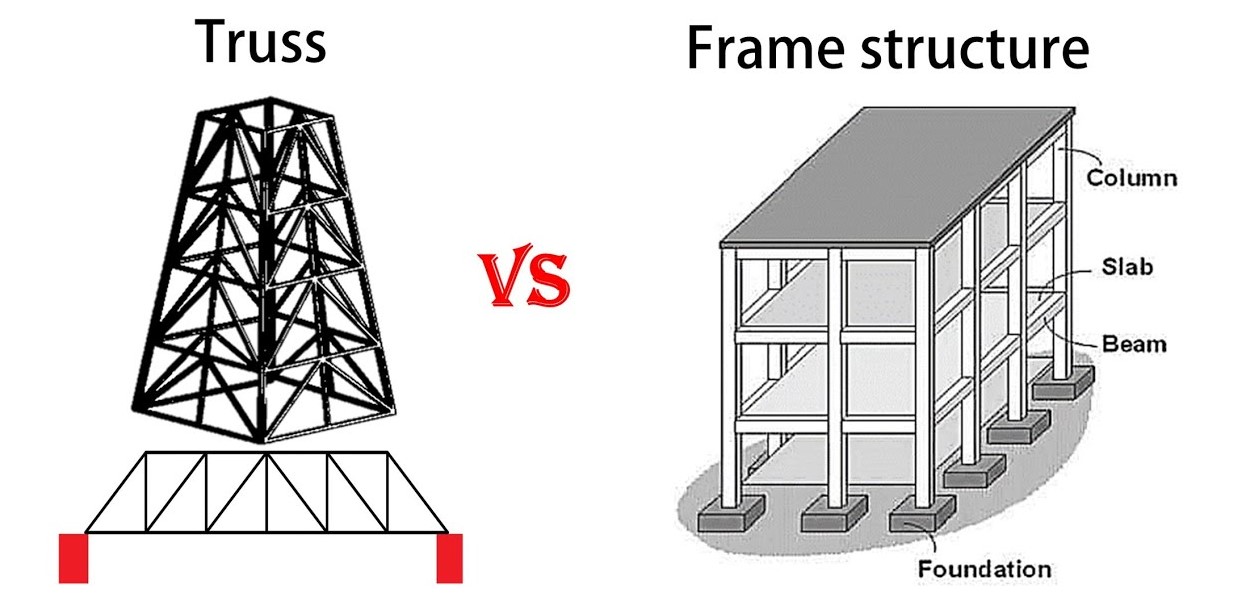
Figure 2: Truss and Frame
1.3. Truss Stability
A truss must be statically determinate and stable. The basic stability condition is:
m+r=2j
where m is the number of members, r is the number of support reactions, and j is the number of joints.
For example, the left-side truss in the following figure (m=3, r=3, j=3 m+r=3+3=6=2j) is stable; while, the right-side truss (m=4, r=3, j=4 m+r=4+3=7 2j) is unstable.
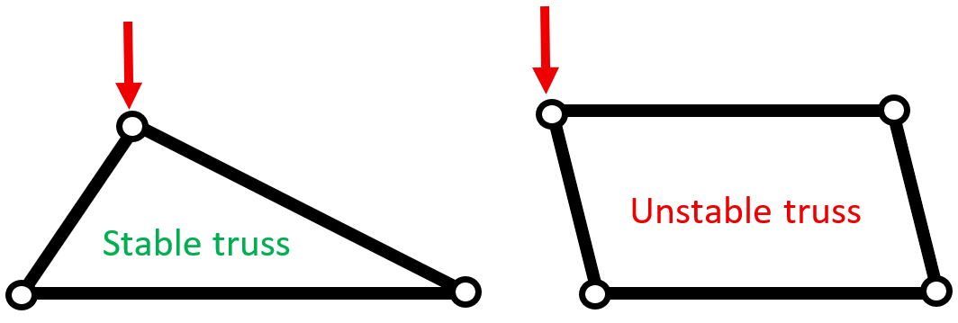
Figure 3: Stability of truss
1.4. Truss Applications
- Bridges (e.g., Pratt, Warren, Howe trusses)

Figure 4: Application of truss in bridges
- Roof supports

Figure 5: Application of truss in roof supports
- Transmission towers

Figure 6: Application of truss in transmission towers
- Aircraft frameworks
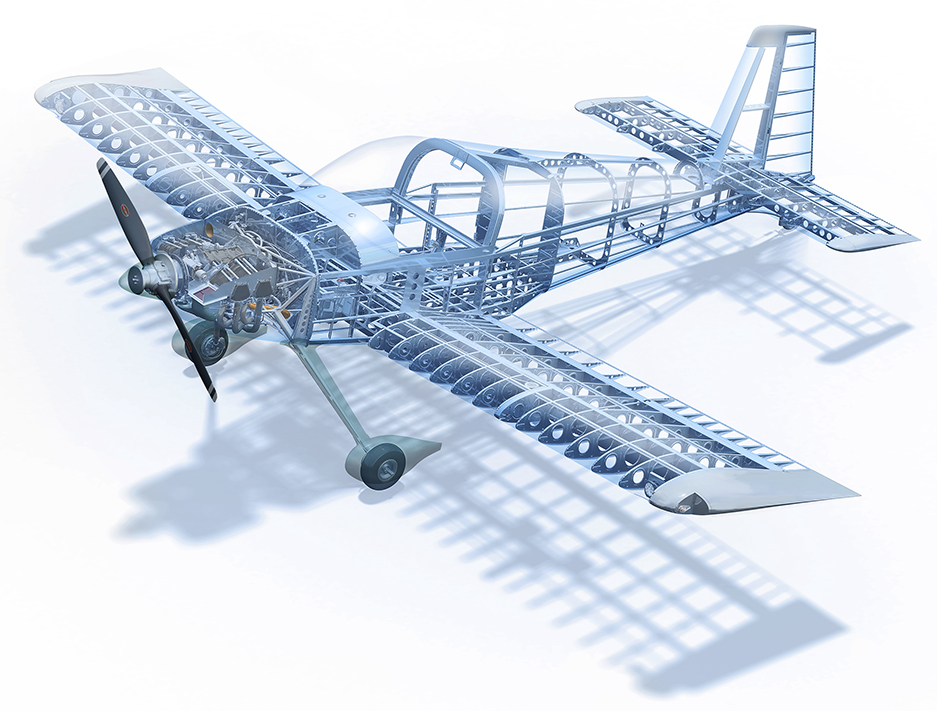
Figure 7: Application of truss in aircraft frameworks
There exists a wide variety of types. Moreover, not every type is appropriate for the intended function of the structure. Before we can proceed with designing a truss, such as a timber truss roof, it is essential to select the most suitable truss type.
There are many varieties of trusses; some commonly used truss-styles, are shown in the following figure.
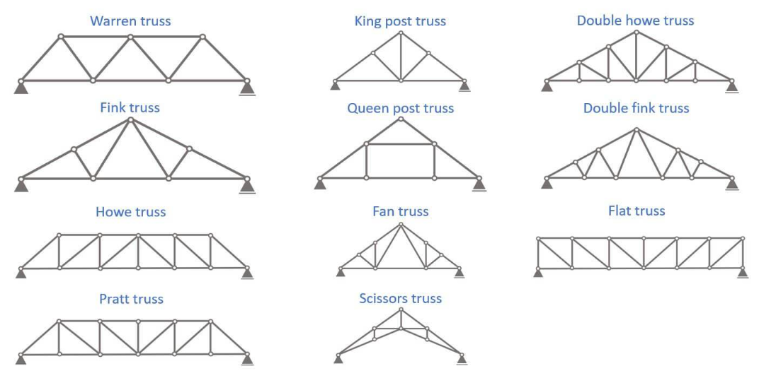
Figure 8: Types of trusses
1.5. Advantages and Disadvantages of Truss Structures
Pros
Excellent weight-to-span ratio: Trusses allow for longer spans with a relatively low weight compared to other structural systems, such as beams, which primarily function through bending. Efficient structures, like trusses, predominantly operate in compression and tension, minimizing bending effects.
Material efficiency: Trusses require less material than beams for the same span, resulting in a more sustainable and cost-effective design.
Structural efficiency: Loads are transferred effectively through the truss system. Each member can be optimized according to the forces it experiences.
Cons
More complex assembly compared to beams.
Increased number of connections: This results in a greater potential for errors and necessitates more maintenance.
Fire safety concerns: Since the connections are made of steel, they exhibit lower fire resistance, as heated steel can ignite wood more rapidly.
2. Truss Analysis Techniques
When examining a truss or what we call “truss analysis”, the primary goal is to ascertain the force within each of its members under a specific set of applied loads. This enables us to verify that the members can support the loads without experiencing failure, or provides us with the necessary information to choose the most suitable cross-section for each member. There are two principal methods available for this purpose – the Method of Joints and the Method of Sections.
- Method of Joints
A node-based method where equilibrium equations are applied at each joint:
-
- Use
 and
and 
- Solve for axial forces in each connected member
- Use
- Method of Sections
A faster technique for analyzing specific members by “cutting” through the truss and applying equilibrium equations to the exposed section.
These traditional methods for truss analysis are foundational and help validate simulation results in Abaqus.
3. Truss Simulation in Abaqus: A Complete Workflow
Let’s now explore how to bring theory into practice with a structured workflow truss simulation in Abaqus.
Setting Up Your Abaqus Model
- Start a New Model Database in Abaqus/CAE
- Define Part as a 2D or 3D wire (depending on problem dimensionality)
- Use “Truss” element type when defining the part
Meshing and Element Selection
- Choose T3D2 (3D) or T2D2 (2D) truss elements
- Ensure correct orientation and connectivity of elements
- Use structured meshing for cleaner force distribution
- It should be noted that in a truss structure, each individual member is ideally treated as a single element in a finite element analysis. This means you wouldn’t break down a truss member into smaller mesh elements; instead, you’d define each member as a distinct element within the overall mesh.
Applying Loads and Boundary Conditions
- Assign boundary conditions at supports (pinned, roller, fixed)
- Apply concentrated forces or distributed loads at joints or along members
- Consider pre-tension if applicable in cables or preloaded members
Running the Analysis
- Create a static general step
- Define field outputs (axial forces, displacements, reaction forces)
- Submit the job and monitor the progress
- Post-process results using deformation plots and XY plots
Advanced Techniques: Handling Statically Indeterminate Trusses
Real-world trusses are often statically indeterminate, meaning they have more members than necessary for equilibrium. In Abaqus, indeterminate systems are automatically solved using stiffness-based finite element methods
In Abaqus:
- You can incorporate nonlinear geometry (Nlgeom) for large displacements
- Introduce initial imperfections or material plasticity for advanced behavior
Common Problems:
- Zero or negative stiffness: Check for unconnected nodes or missing BCs
- Unrealistic deformations: Validate units and element types
- Solver errors or convergence issues: Check mesh or use nonlinear steps
4. Case Study: Analyzing a Real-World Truss Structure in Abaqus
In this section, a simple example will be explained to learn how to simulate truss structure analysis in Abaqus. In this example, we intend to calculate the stress in truss using the Abaqus software and analytical solution and following that, compare the results obtained from the Abaqus software with those of analytical solution.
Problem description: Consider a bridge truss as shown in figure 9. The cross-sectional area of truss members is 5.87 in2 .
- Determine the normal stress in member BE using analytical solution
- Determine the normal stress in member BE using Abaqus software
- Compare the answers of A and B
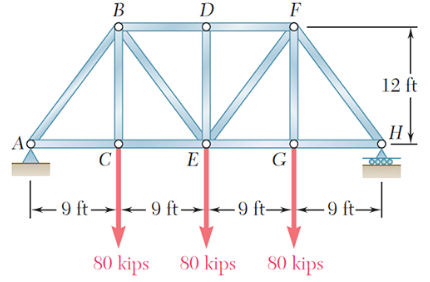
Figure 9: Pratt bridge truss
4.1. Analytical solution using method of sections
First we determine the reactions forces of the boundary conditions.
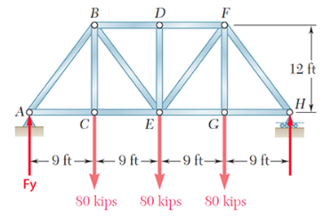
Figure 10: Reaction forces
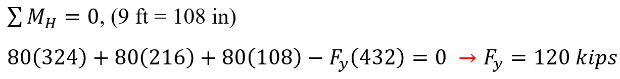
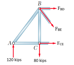
Figure 11: Left section of the truss
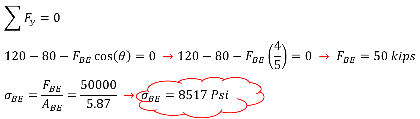
Therefore, the stress in member BE obtained from the analytical solution is equal to 8517 Psi.
4.2. Abaqus truss Simulation
1. Geometry Definition:
Create a new part:
Start Abaqus and create a new model database. Then, create a new part, selecting “2D Planar,” “Deformable,” and “Wire”. Set an approximate size for the part, which will help with the later meshing process.
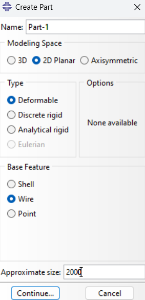
Figure 12: Creating the truss part
Create the truss geometry by sketching the individual members as lines or using the “Create Wire” tool.
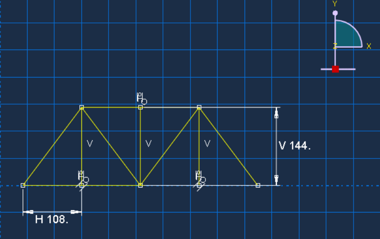
Figure 13: Sketching the truss
2. Material and Section Properties:
- Create a material: Define the material properties, such as Young’s modulus and Poisson’s ratio.
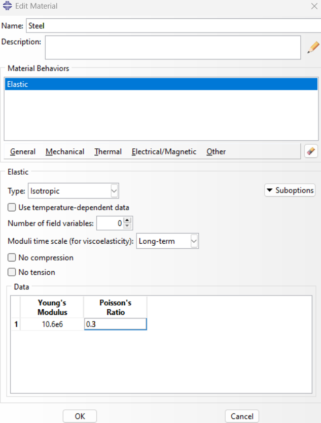
Figure 14: Defining material properties
- Create a section: Create a truss section, specifying the cross-sectional area. If no area is specified, Abaqus will assume a unit area.
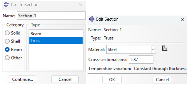
Figure 15: Creating section
- Assign the section: Assign the defined section to the truss members.
3. Assembly and Step Definition:
- Instance the part: Create an instance of the part in the assembly module.
4. Define the analysis step: Create a static, general analysis step.
- Set analysis parameters: Set parameters such as the time period for the analysis.
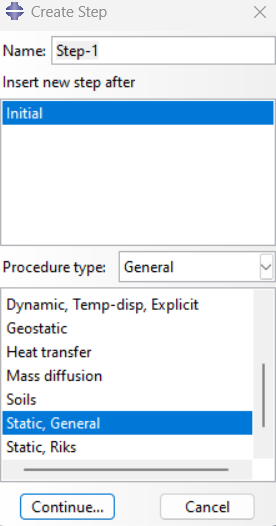
Figure 16: Defining step
5. Boundary Conditions and Loads:
- Apply boundary conditions: Apply constraints to restrict movement at the supports (e.g., fixed supports or hinges).
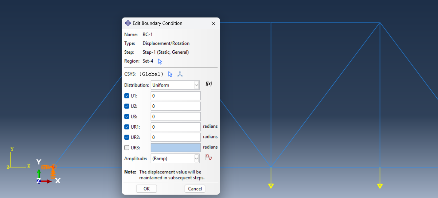
Figure 17: Left support
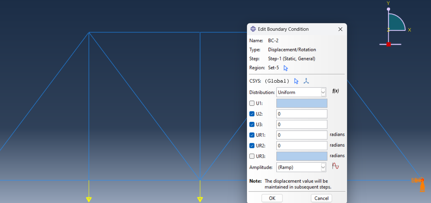
Figure 18: Right support
- Apply loads: Apply the desired forces or pressures to the truss members or nodes.
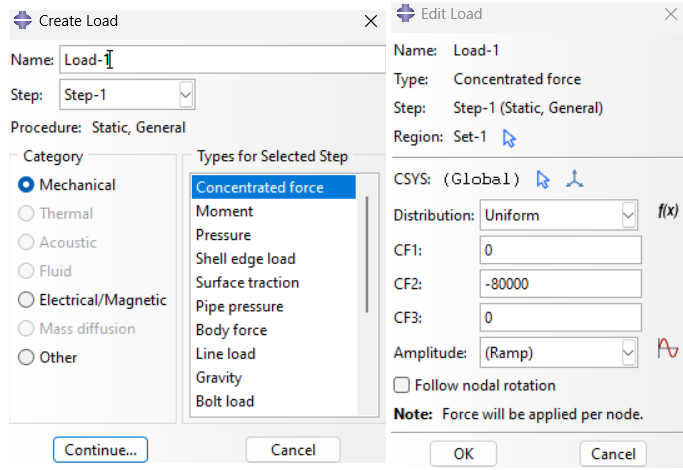
Figure 19: Creating Concentrated force
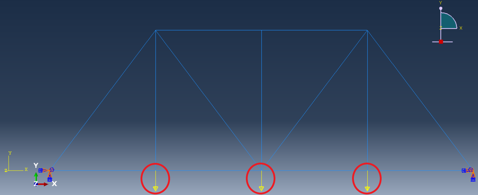
Figure 20: Concentrated force on truss nodes
6. Mesh Generation:
- Seed the part: Create mesh seeds on the truss members.
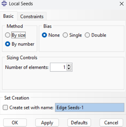
Figure 21: Creating mesh seeds on truss members
- Mesh the part: Mesh the part using the defined seeds, ensuring the elements are truss elements (T2D2).
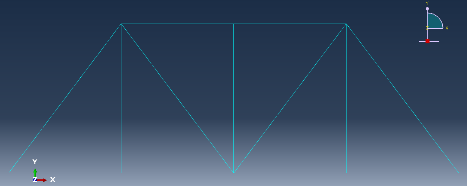
Figure 22: Meshed truss
7. Analysis and Results:
- Create a job: Define a job to run the simulation.
- Submit the job: Submit the job for analysis.
8. View results:
Once the analysis is complete, view the deformed shape, stress, and strain distributions in the Visualization module.
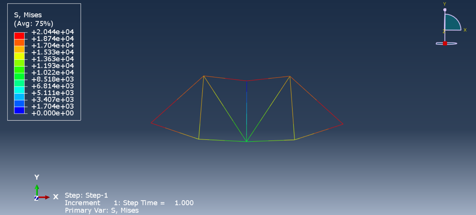
Figure 23: Viewing stress results
In order to display normal stress (S11) for BE member in a tabular format within Abaqus results XY data, you need to create an XY data plot from field output, specify the stress component, select the BE element, and then output the data in a table (As shown in the following figures).
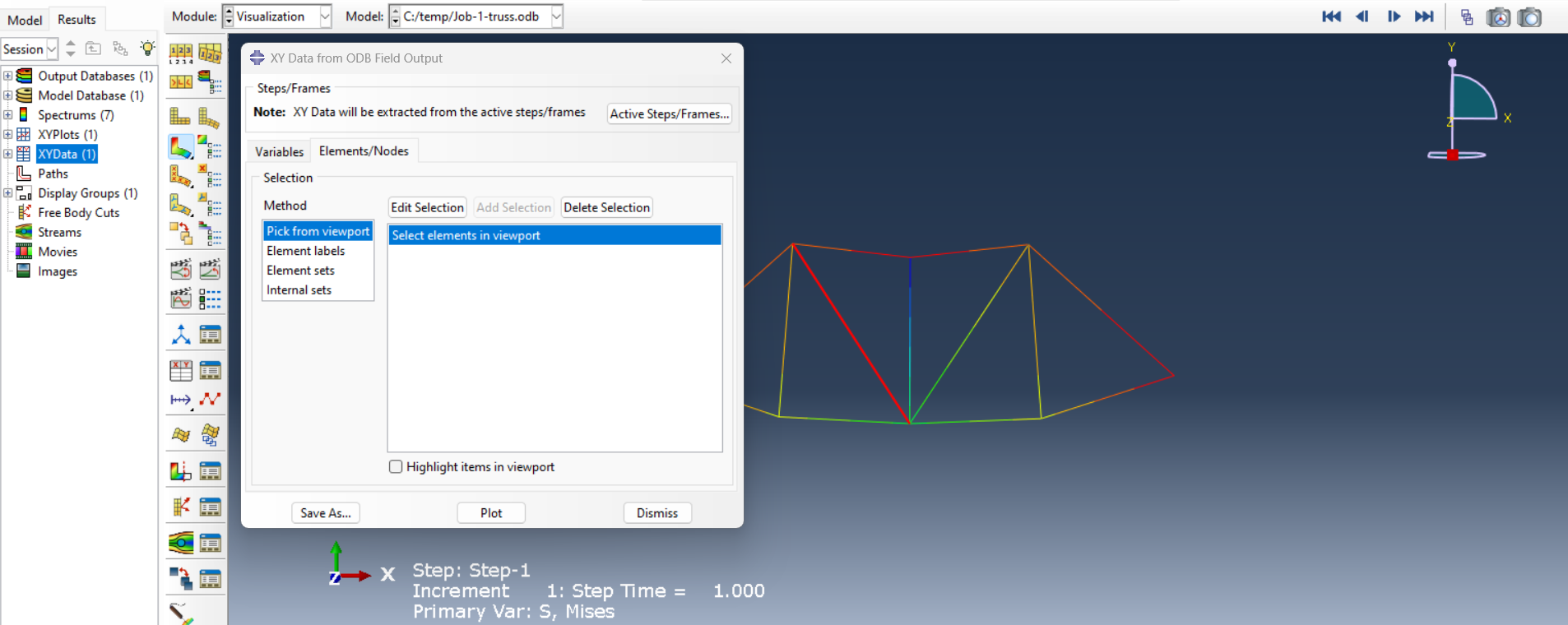
Figure 24: Creating stress plot for one element
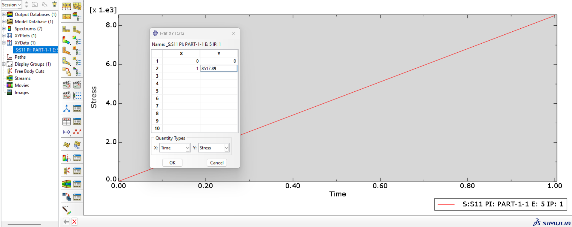
Figure 25: Stress plot for BE element
Here’s a table outlining comparison of each method outcome:
| Solution method | Analytical | Simulation |
|---|---|---|
| Normal stress value | 8517 Psi | 8517.89 Psi |
It is observed that the results obtained from the Abaqus software are so close to those gained from the analytical solution.
5. Conclusion
This article explored truss analysis using the Abaqus software. It explained how trusses, which are made of axial-force members, are analyzed to ensure safety and efficiency. Because these structures are widely used in bridges, towers, and buildings, accurate truss simulation is essential for design validation.
We first discussed truss elements and how they differ from frames. The conditions for stability were also outlined. Then, two key analysis methods were introduced: the Method of Joints and the Method of Sections. These methods are useful for calculating internal forces and checking results from simulations.
Next, we covered the complete simulation process in Abaqus. This included creating the model, assigning material properties, setting boundary conditions, meshing, and running the analysis. The blog also explained how to handle statically indeterminate trusses using FEM and gave tips for solving common issues.
In the final section, a real-world case study compared analytical and simulation results for a bridge truss. The results matched closely, showing that truss simulation in Abaqus can deliver accurate outcomes. Overall, this article provided both theoretical background and practical steps for performing reliable truss analysis using FEM tools.
Explore our comprehensive Abaqus tutorial page, featuring free PDF guides and detailed videos for all skill levels. Discover both free and premium packages, along with essential information to master Abaqus efficiently. Start your journey with our Abaqus tutorial now!