What is Abaqus Load Torque (Moment) and How to Apply it in Abaqus?
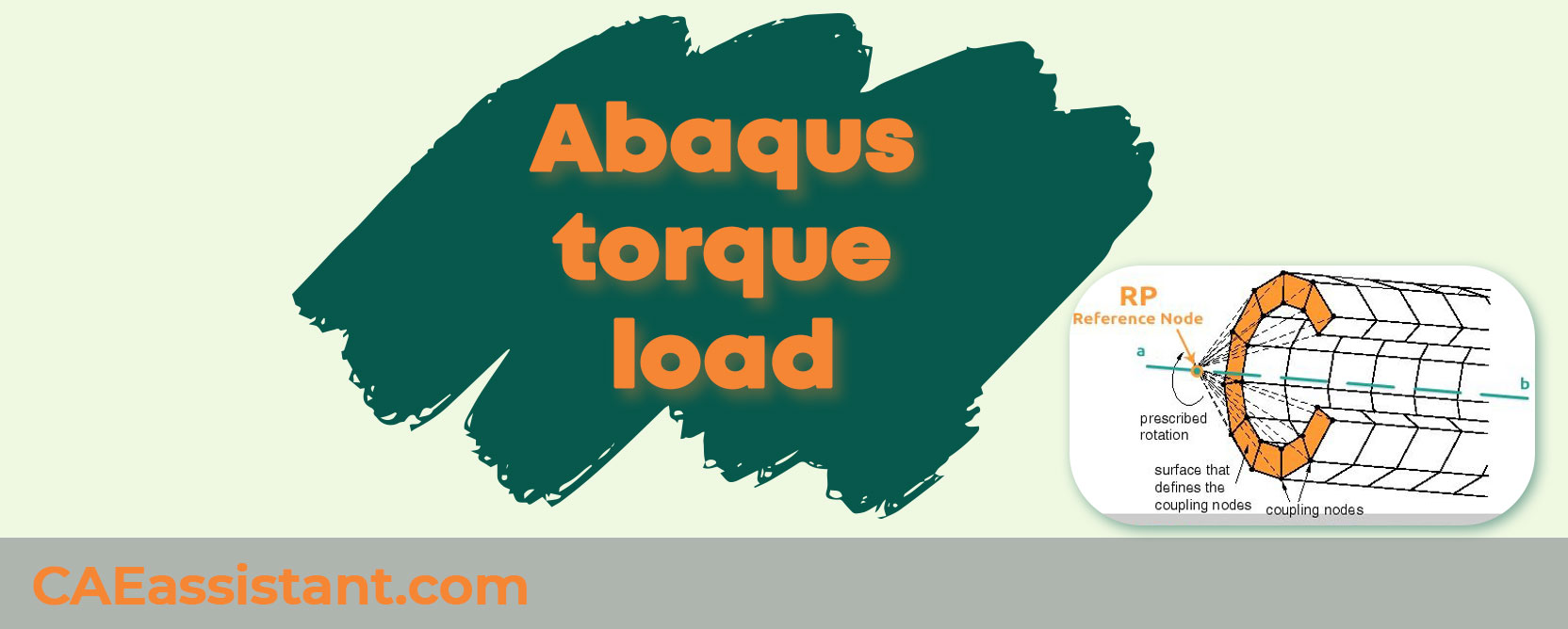
When it comes to simulating real-world scenarios in Abaqus, understanding the concept of torque load and moment load is crucial. In simple terms, torque load and moment load are both measures of rotational force, but they are often used interchangeably, leading to confusion.
But before we go any further, let’s define each one first, then tell you the difference between them. Yes, there is difference between these two concepts. And after that, we tell you how to apply torque load and moment load in Abaqus in detail (Abaqus torque & Abaqus Moment).
Keywords: Abaqus load torque, Abaqus moment, Abaqus torque
1. What is Torque Load?
Torque is a specific type of rotational force that causes an object to spin around an axis. It is often associated with mechanical systems where rotational motion is a key element, such as engines, gears, and tools like wrenches. The formula for torque (𝜏) is:
where:
- r is the perpendicular distance from the pivot point to the line of action of the force (lever arm).
- F is the magnitude of the force applied.
- θ is the angle between the force vector and the lever arm.
Key Characteristics of Torque:
- Nature: A twisting force causing rotation.
- Torque is a vector quantity, having both magnitude and direction.
- Unit: Newton-meter (N·m).
- Application: Rotational systems (e.g., turning a doorknob, tightening a bolt with a wrench). Torque is commonly encountered in scenarios involving engines, wrenches, and rotating machinery.
2. What is Moment Load?
Moment load, or simply “moment,” is a more general term used to describe the tendency of a force to cause rotation about a point or axis. It encompasses a wider range of scenarios compared to torque, including bending moments in structural engineering.
The general formula for a moment (M) is:
where r and F have the same definitions as in the torque formula, but the angle is implicitly perpendicular in many structural applications.
Key Characteristics of Moment Load:
- Nature: Any force causing rotational or bending effects.
- Unit: Newton-meter (N·m).
- Moment load is also a vector quantity.
- Application: Structural engineering (e.g., bending moments in beams, seesaws). It is used extensively in structural engineering to analyze beams, bridges, and other structures where bending moments are crucial.
3. Are there any differences between Torque Load and Moment Load?
To set the record straight, torque load and moment load are essentially the same thing – they both describe a force that causes an object to rotate. Think of it like using a wrench to tighten a bolt. The force you apply to the wrench is a torque load, and it causes the bolt to rotate.
The key takeaway is that both torque load and moment load refer to a twisting force that causes rotation, but the terminology used might vary depending on the context. To further clarify, the term “torque” is often used in engineering and physics to describe the rotational force, while “moment” is more commonly used in mechanics and mathematics to describe the same concept. So, whether you call it torque load or moment load, the fundamental concept remains the same – it’s a force that causes rotation, and understanding it is essential for accurate simulations in Abaqus.
But let’s summarize it:
Application Context
- Torque: Typically used in the context of rotational systems and mechanical applications where actual rotation occurs.
- Moment Load: More commonly used in structural engineering to refer to bending moments.
Specificity
- Torque: Often implies rotational motion or the potential for rotation.
- Moment Load: Can refer to bending or rotational forces but is broader in application.
Visual and Conceptual Differences
- Torque: Visualized as a force causing rotation around a fixed point or axis (e.g., gears, engines, and rotating shafts).
- Moment Load: Visualized in structural contexts, often showing bending effects (e.g., a beam under load).
4. Applying Torque Load and Moment Load in Abaqus | Abaqus torque & Abaqus moment
When working with Abaqus, applying torque load or moment load (Abaqus torque & Abaqus moment) involves defining boundary conditions that simulate rotational forces. Although torque and moment load have conceptual differences, in Abaqus, they are treated similarly in terms of application. Here’s a step-by-step guide on where to begin and the available methods for applying these loads in Abaqus.
Open Abaqus/CAE:
Start Abaqus/CAE and open your existing model or create a new one.
Create or Open a Model:
Navigate to the ‘Model’ database to select the model where you want to apply the load.
Defining the Load:
- Go to the ‘Load’ module.
- Select Create Load from the toolbar or the Load menu.
Select the Step:
Choose the analysis step during which the torque or moment load will be applied.
Choose Load Type:
In the Create Load dialog box, select Moment to apply a torque or moment load.
Select Region:
Select the nodes or reference points where the torque will be applied. Abaqus does not support applying moments directly to surfaces.
- For Nodes:
Select individual nodes where you want to apply the moment.
- For Reference Points:
Create a reference point and couple it to the desired region (e.g., using a coupling constraint) to apply the moment at this reference point.
Specify Load Magnitude:
Enter the magnitude of the moment load (torque) and specify the direction or axis around which the torque will act. This could be in terms of moment components or as a rotational direction.
Apply and Review:
Apply the load and review it in the Load Manager to ensure it is correctly defined.
But, let’s dive deeper in details.
5. How to apply Abaqus load torque?
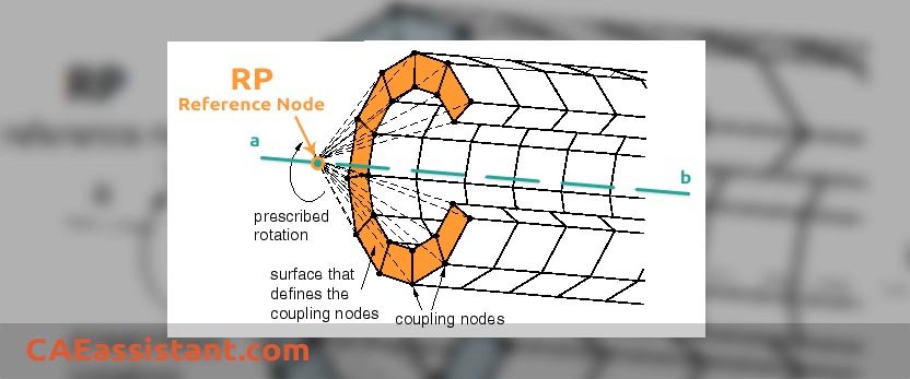
As you may know, elements like continuum (solid) have no rotational degree of freedom. Therefore, you cannot apply moments nor rotations directly when using them. Then, the only way to apply torque is through a coupling constraint. You have to put a moment on a reference point and connect this point with the points on your structure (Abaqus load torque).
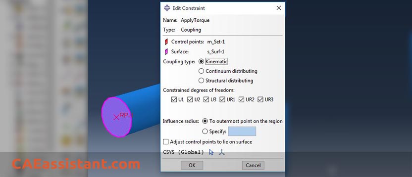
Kinematic coupling constrains the motion of the coupling nodes to the rigid body motion of the reference node. The constraint can be applied to user-specified degrees of freedom at the coupling nodes with respect to the global or a local coordinate system.
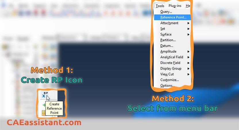
1. [In any module before Mesh] create a reference point (named as RP in Abaqus)
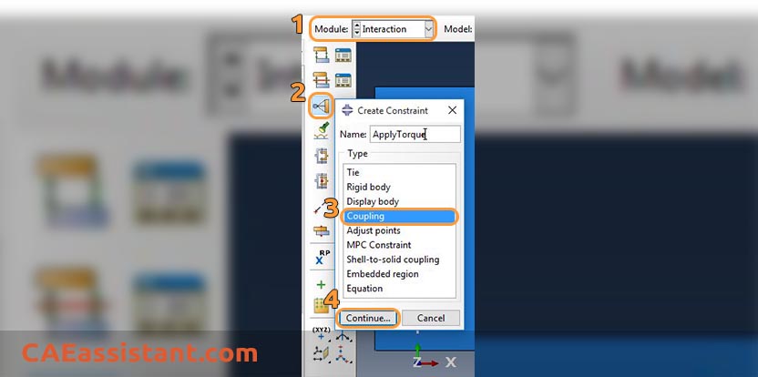
2. [In Interaction Module] define a coupling constraint:
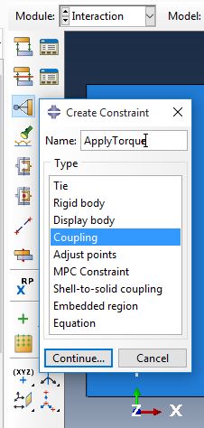
Create Constraint > Type=Coupling > select RP as your constraint control point > select either Node Region or Surface (depending on your model) > Coupling Type=Kinematic
3. Apply your torque (moment) or rotational BC to defined RP
Also, there is a Tie constraint in the figure above; what is the difference between Tie and coupling? and wait, there is a Rigid body constraint as well. what is the difference between these three, huh? You can get your answers in the Lesson One of the Abaqus tutorial.
Notes:
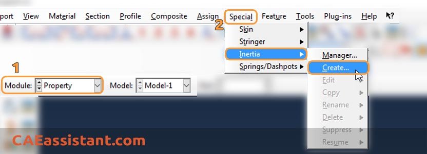
1. If you are using Abaqus/Explicit as solver (Steps like Dynamic, Explicit), you MUST assign Inertia to your RP avoid facing Error in job submission. In Properties module, in Menu Bar, select Special > Inertia > Create.
6. Rotation around an axis
I’m trying to model rotational displacement with Abaqus’ static technique. I found an example of a dynamic procedure but I couldn’t find any for this problem. Does anybody know how to rotate the attached ring around axis y in Abaqus?
I have three recommendations for you:
- First, you can define a reference point in the center of the ring and create the coupling constraint between the point and the ring. Then, apply the “Displacement/Rotation” boundary condition.
- Second, create a rigid plane, place it on top of the ring, make tie constraint, and then apply rotation on the reference point of the plane.
- Third, create a rigid cylinder and place it in the ring. Make tie contact between the inner surface of the ring and the outer surface of the cylinder. Then, apply rotation on the reference point of the cylinder.
I think the last two are better because local deflections may occur in the first solution.
|
If you’re new to FEM and FEA, just starting with Abaqus, or looking to strengthen and organize your knowledge of the software, the “Abaqus for Beginners“ package is the perfect place to start. It’s designed to guide you from the basics all the way to confident, professional-level use. |
Need help finding specific errors, examples, or details about any feature in Abaqus? The Abaqus Documentation is your go-to resource—but navigating it can be tricky. This package walks you through exactly how to search and use the documentation effectively. |
7. Conclusion
Understanding and accurately applying torque and moment loads in Abaqus is crucial for precise simulations. Torque is a specific type of rotational force causing an object to spin around an axis, commonly used in mechanical contexts. Moment load is a general term for forces causing rotational or bending effects, often used in structural engineering. In Abaqus, both loads are applied similarly: directly to nodes, using reference points and coupling constraints, defining discrete rigid bodies, or through multi-point constraints (MPCs). Following the steps to create a load, select the analysis step, choose the Moment load type, and specify the load on nodes or reference points ensures accurate simulation of complex phenomena, enhancing design insights for engineers and researchers.
You can always find more info in Abaqus documentation; but use it might sometimes be tricky and all that info overwhelm you. With our “How to use Abaqus documentation” tutorial you will have no issue anymore and find your answers without any problem.
One note, when you are simulating in Abaqus, be careful with the units of values you insert in Abaqus. Yes! Abaqus don’t have units but the values you enter must have consistent units. You can learn more about the system of units in Abaqus.
Read More: What is Follower Force? | The Guide for Abaqus “Follow Nodal Rotation” Option

