
Composite Pressure Vessel: The Best Guide to Production and Simulation Method
Did you know the next rocket soaring into space might be powered by a pressure vessel lighter than your backpack? Composite pressure vessels exhibit higher resistance to corrosion, and temperature variations compared to traditional vessels. but what do you really know about them? How much do you know about a Composite Pressure Vessel production methods, applications, and the different materials used in its fabrication? Are you interested in learning more about modeling and simulation of these pressure vessels in a software like Abaqus?
This blog can provide the best answers to your questions. In this blog, we will first familiarize ourselves with pressure vessels and their various types. Then, we will delve into composite vessels and their fabrication methods. The next step will be to provide information on simulating composite pressure vessel in Abaqus. Additionally, we will discuss failure criteria for composites, such as the Puck theory. Let’s dive in and explore this article together.
Design and simulation of composite pressure vessels in Abaqus. Learn filament winding techniques—planar, geodesic, and isotensoid—through guided lessons and hands-on workshops. Automatic simulation just by a few clicks and importing some input data; HOW? Python Scripting and step by step guide plus analyzing damage with Puck criterion through UMAT subroutine.
 |
Lesson 1: What are the pressure vessels?
Lesson 7: How to choose the best method?
|
1. What are pressure vessels?
A pressure vessel is a container designed to hold gases or liquids at different pressures than ambient pressure; for example, CNG and LPG tanks for automobiles, compressed air tanks, pressure vessels used in the oil and gas industry, and submarines are pressure vessels.
The design and manufacture of pressure vessels are crucial due to their operation at high pressures and the presence of risky substances such as toxic gases. Various methods, including destructive and non-destructive testing, are employed to assess the performance and ensure the proper safety of these vessels. However, to save time and production costs, software such as Abaqus can be used for simulating and analyzing these vessels.
The manufacturing methods and materials used for pressure vessels may vary based on the applied pressure and factors such as vessel size, contents, working pressure, mass constraints, and volume limitations. Therefore, it is best to review the materials used, vessel shapes, and production methods for these vessels.
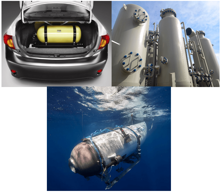
Figure 1: Pressure vessels in different industries

1.1. Pressure Vessel Shapes
Pressure vessels can be manufactured in various shapes, but they are typically made in the form of cylinders, spheres, or ellipsoids. The reason for commonly using these mentioned geometries is that manufacturing vessels with other shapes can be very challenging. Additionally, performing calculations for advanced geometries is time-consuming and costly. Among the mentioned geometries, spherical vessels are used more frequently for storing fluid due to their uniform distribution of internal and external stresses and the requirement for less material. However, due to the complexity of manufacturing spherical vessels, a combination of a cylindrical body with hemispherical ends is commonly used for pressure vessels.
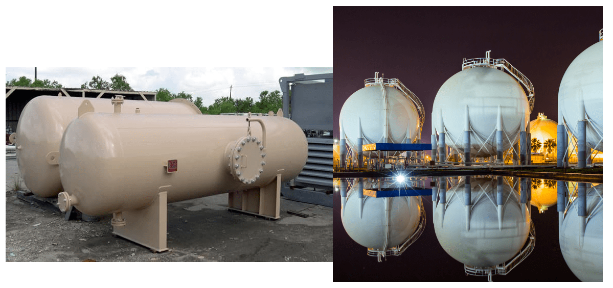
Figure 2: Spherical and cylindrical pressure vessels
1.2. Pressure Vessel Materials
As we mentioned, the materials used for manufacturing pressure vessels are usually chosen based on the vessel’s applications. For example, factors such as the nature of the fluid being stored, the operating pressure, the designed geometry of the vessel, the surrounding environment, the cost, and the availability of materials are all influential in selecting the appropriate material for a vessel.
|
Explore our comprehensive Abaqus tutorial page, featuring free PDF guides and detailed videos for all skill levels. Discover both free and premium packages, along with essential information to master Abaqus efficiently. Start your journey with our Abaqus tutorial now! |
In general, metals are widely used and popular for manufacturing pressure vessels. Vessels made from metal sheets have a lower cost, and they are relatively easy to manufacture. Steel, aluminum, and nickel alloys are among the favored metals for pressure vessel manufacture. However, some pressure vessels are made using polymers and composites. These vessels are produced with significantly lower weight and exhibit better resistance to corrosion. However, they are much more expensive and typically require complex manufacturing processes. One of the most well-known composite vessels is the one made with carbon fibers and resin. Let’s review the cases where composite pressure vessel has replaced conventional pressure vessel:
- Oil and gas industries: In the oil and gas industry, the composite pressure vessel is used for storing high-pressure fuels such as compressed natural gas (CNG) and hydrogen. These vessels are utilized as suitable alternatives to metal vessels due to their lightweight, high resistance to corrosion, and superior mechanical strength.
- Transportation: The Composite pressure vessel is employed in transportation for storing high-pressure fuels in vehicles, such as CNG buses and hydrogen-powered cars. These vessels are considered ideal options for advanced fuel systems in urban and intercity transportation due to their lightweight, larger storage capacity, and enhanced safety.
- Chemical industries: Composite pressure vessel serves as substitutes for metal vessels in storing dangerous chemicals in the chemical industry. These vessels are preferred for their high resistance to corrosion and chemical effects, reduced leakage risk, and lower tendency for explosions, making them an ideal choice for this sector.
- Renewable energy: In the renewable energy industry, composite pressure vessels are used for storing hot water and compressed natural gases. These vessels have become a suitable choice due to their high thermal insulation, reduced energy loss, and enhanced energy efficiency.
- Absorbent and separator materials: In certain space missions, the use of absorbent and separator materials is essential. A Composite pressure vessel is utilized as a compartment for storing these materials in space. These vessels are suitable for this application due to their lightweight, high resistance to pressure and temperature variations, and the lack of impact of absorbent materials on vessel properties.
- Space oxygen systems: Spacecraft and space stations utilize space oxygen systems to provide oxygen to astronauts. Composite pressure vessels are employed in these systems.
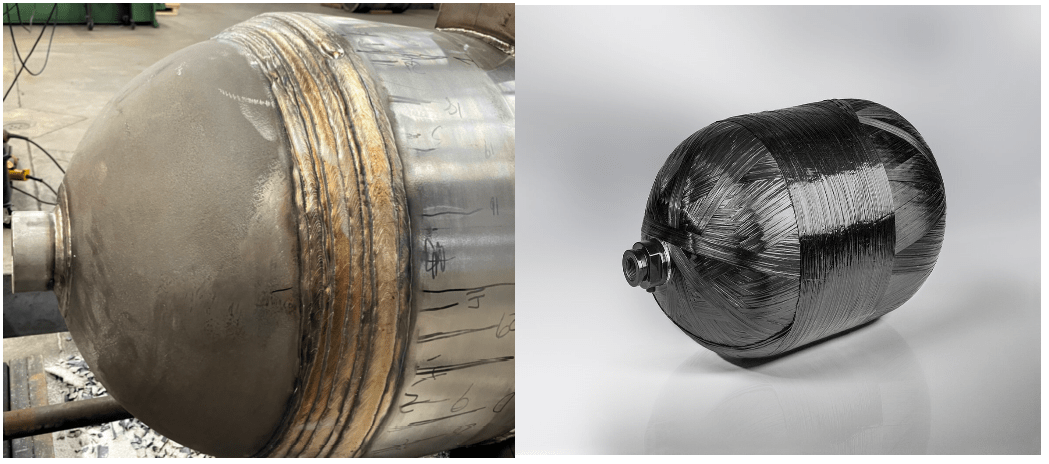
Figure 3: Metal and composite pressure vessel
1.3. Composite Pressure Vessel (CPV) Cons and Pros
As mentioned, composite vessels have advantages such as significantly lower weight compared to metal vessels, which is why their use has increased. The presence of continuous and high-length fibers in these vessels allows for better tensile performance of the vessel’s wall. Sometimes, in the production of these vessels, metal or polymer are also used as liners, although it is possible for the vessel to be entirely made of composite materials. However, in most cases, metals are used for the inlet and outlet flanges of these vessels.
Generally, composite and metal pressure vessels have their own advantages and disadvantages. Now, we will examine the pros and cons of these two types of vessels:
- Lightweight: Composite pressure vessel is made of composite material that is much lighter in weight compared to metals. This feature reduces the overall weight of the system and consequently improves the system’s performance.
- High resistance to corrosion: Composite materials have greater resistance to corrosion and rust compared to metals. This means a longer service life and reduced repair and maintenance.
- Flexibility: A Composite pressure vessel is made of more flexible materials. This characteristic assists in adjusting the pressure inside the vessel, and they can be easily designed in various shapes and sizes.
- Production cost: Composite materials are generally more expensive than metals, and manufacturing a composite pressure vessel entails higher costs.
- Repair and maintenance: If a section of a composite vessel gets damaged, repairing it may be challenging or even impossible. Depending on the structure and type of composite used, it may be necessary to destroy or completely drain the vessel to repair or replace the defective part. Additionally, repairing and maintaining these vessels usually requires advanced and costly equipment.
- Heat transfer: Metals can quickly heat up or lose heat. This issue can be problematic in certain applications, such as sustaining the desired temperature inside the vessel.
2. How is a Composite Pressure Vessel made? | Composite Pressure Vessel Design
As previously mentioned, one of the most important composite pressure vessel cons is their manufacturing high cost. Therefore, there is a need to simulate these vessels before their production to ensure the accuracy of the composite pressure vessel design compared to metal pressure vessels. To simulate and analyze a composite pressure vessel in Abaqus, it is necessary to be familiar with the filament winding method used to produce the composite pressure vessel. This method is also used for manufacturing pipes. In this process, resin-impregnated fibers are wound onto a rotating mandrel with a specific angle and thickness using a filament winding machine. The filament winding machine moves back and forth along the axis of the mandrel. Figure 4 schematically shows the filament winding process.
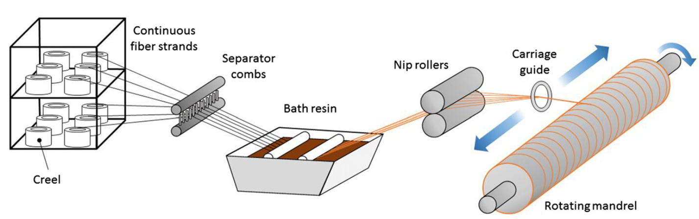
Figure 4: Fiber winding process schematic [Ref]
According to the explanations provided about the filament winding process, it is challenging to perform filament winding on domes or mandrels with complex geometry. It requires advanced and expensive equipment to accomplish. Therefore, one of the challenges of the filament winding method is the need for complex equipment.
Now that we have some knowledge of the filament winding process, we can examine in more detail the factors that influence the manufacture of a filament-wound vessel.
2.1. Winding Angle
The winding angle in pressure vessels refers to the angle between the tangent line along the fiber path and the axis of the mandrel. The winding angle is one of the most influential parameters in the design and production process of a pressure vessel. Sometimes, the winding angle can lead to fiber slippage on the mandrel surface during winding. Additionally, the winding angle affects the level of pressure exerted on the fibers. As a result, determining this angle holds significant importance. But how is the value of the winding angle determined?
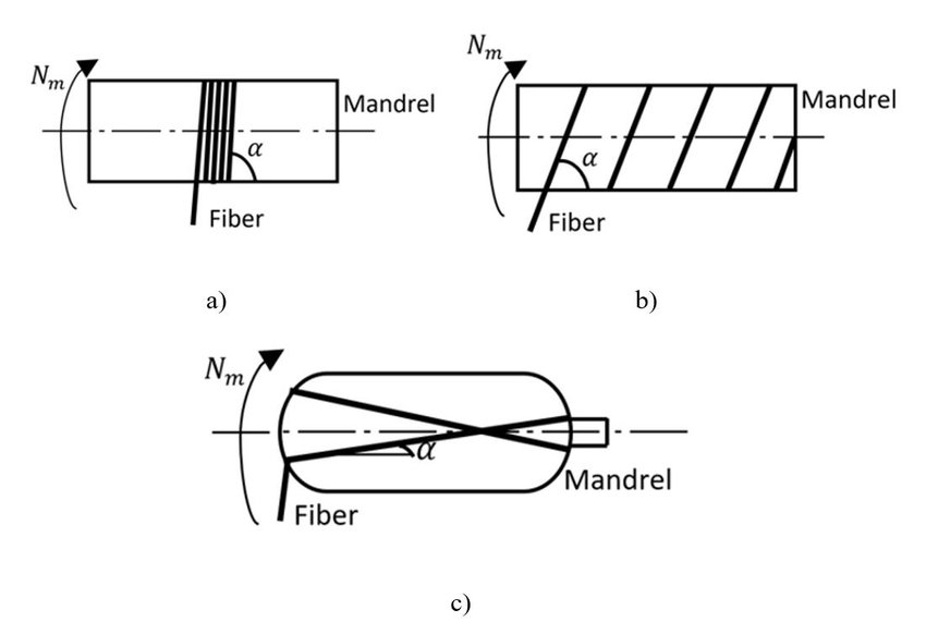
Figure 5: Filament finding angel [2]
In general, for filament winding, there are three types of winding patterns. The first type is polar winding where the absolute value of the winding angle is less than 25 degrees. The second is spiral winding, where the absolute value of the winding angle is between 20 and 90 degrees. semi-geodesic and geodesic winding are also of this type. And the third type which the winding angle is very close to 90 degrees is called circumferential winding.
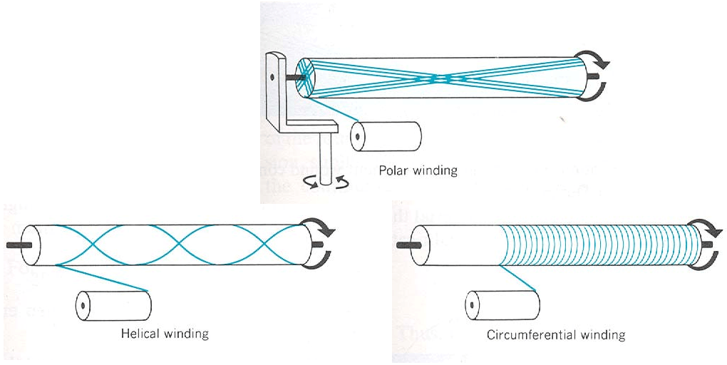
Figure 6: Three Patterns of filament winding [3]
2.2. Winding Thickness
Another parameter in the design and production of pressure vessels using the filament winding method is thickness. The thickness of the vessel is not only important for its performance and resistance against internal and external pressures but also influences the cost of manufacturing pressure vessels. Therefore, determining a safe and optimal thickness for pressure vessels is very important. In the following sections, we will discuss the methods and common winding patterns and we will determine their thickness.
Now that we have some information about the filament winding method and its parameters, it is time to explore the methods and common patterns of filament winding.
 |
⭐⭐⭐ Free Abaqus Course | ⏰10 hours Video 👩🎓+1000 Students ♾️ Lifetime Access
✅ Module by Module Training ✅ Standard/Explicit Analyses Tutorial ✅ Subroutines (UMAT) Training … ✅ Python Scripting Lesson & Examples |
2.3. Geodesic Winding
In mathematics, a geodesic path refers to the shortest path between two points in space. In geodesic winding which is a type of helical winding, the fibers slip on the surface of the mandrel and follow the shortest possible path between the two ends of the vessel which is known as the geodesic path. The reason for fiber slippage on the mandrel’s surface is insufficient friction between the fibers and the mandrel. Therefore, in this type of winding, friction is considered to be zero. Figure 7 shows a pressure vessel under production using the geodesic winding method.
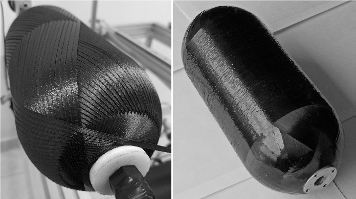
Figure 7: A pressure vessel under production by the geodesic winding method [Ref]
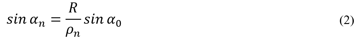
If in the force analysis of the fibers, the friction is considered equal to zero, we get an equation known as Clairaut’s equation.
![]()
In this equation, α0 represents the winding angle in the cylindrical region, ρn is the radius in the dome region, R is the radius in the cylindrical region, ρb1 and ρb2 represent the radii of the left and right dome openings respectively, and αn is the winding angle in the dome region. Based on Clairaut’s equation, we can conclude that the radii of the two dome openings must be equal. Additionally, with the help of this equation, we can derive the equation for the winding angle in the dome region.
As mentioned earlier, thickness is an influential parameter in the performance of pressure vessels. Due to the shape of the mandrel and the radius reduction in the dome regions, fibers are stacked on top of each other at both ends of the vessel, leading to an increase in thickness. These thickness variations in the dome region must be accounted for in simulations. The following equation is used to determine the thickness of each section of the dome. Here, tn represents the thickness in the dome region, and t0 represents the thickness in the cylindrical region.
2.4. Semi-Geodesic Winding
In semi-geodesic winding, unlike geodesic winding, fibers do not move freely on the mandrel, so the friction is not zero. If the friction is not zero, the Clairaut’s equation is no longer applicable for calculating the winding angle and we need to use Equation 4 which is the differential equation of the fiber path. By replacing the friction value in this equation, we can calculate the winding angle. In this equation, λ represents the tendency to slippage, where we substitute the friction. r is the radial coordinate, and ![]() and
and ![]() are the first and second derivatives of the radial coordinate with respect to the mandrel axis. ζ is the fiber path variable, and A is also calculated using Equation 5.
are the first and second derivatives of the radial coordinate with respect to the mandrel axis. ζ is the fiber path variable, and A is also calculated using Equation 5.
![]()
2.5. Planar(Polar) Winding
In planar winding, the winding angle in the cylindrical region, as mentioned before, should be less than 25 degrees. In this method, unlike previous approaches, the radii of the left and right dome openings can be different. One of the advantages of planar winding is its high production speed, which is due to the simplicity of winding at both ends of the vessel.
You can have the complete explanation of “What is Semi-Geodesic Winding?“ in the Lesson 1 of the tutorial below; in this lesson we explain:

Figure 8: Production of a pressure vessel by planar winding method
In the planar winding pattern, the winding angle for the cylindrical and dome regions is calculated separately. We can use Equation 4 to calculate the winding angle in the cylindrical region. Figure 9 illustrates the parameters used in Equation 6.
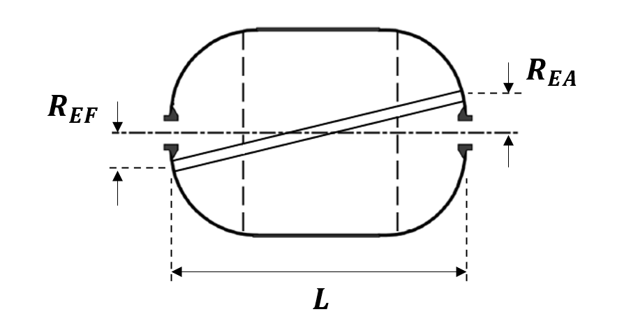
Figure 9: Schematic of planar winding around a mandrel
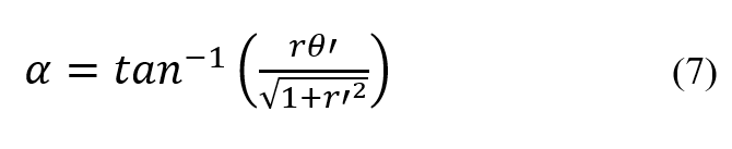
To calculate the winding angle in the dome region for the planar winding pattern, we need to use Equation 7. In this equation, ![]() represents the derivative of the angular coordinate with respect to the x coordinate.
represents the derivative of the angular coordinate with respect to the x coordinate.
To calculate the thickness in the planar winding pattern, Equation 8 should be used.
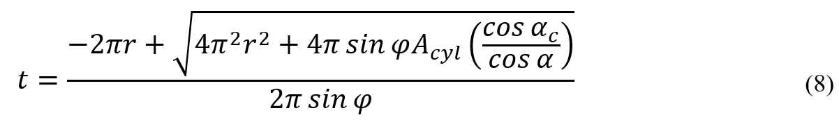
In Equation 8, ![]() represents the angle between the last winding band and the perpendicular line, and
represents the angle between the last winding band and the perpendicular line, and ![]() is the cross-sectional area of the composite in the cylindrical region of the vessel. Figure 10 effectively illustrates the cross-sectional area
is the cross-sectional area of the composite in the cylindrical region of the vessel. Figure 10 effectively illustrates the cross-sectional area ![]() .
.
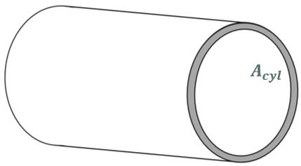
Figure 10: Composite cross section in the cylindrical part
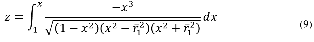
2.6. Isotensoid Winding
The isotensoid winding pattern does not differ from the geodesic winding pattern. Therefore, the winding angle and thickness for isotensoid winding are calculated using Equations 2 and 3, respectively. Isotensoid winding distinguishes itself from geodesic winding by two conditions: firstly, the vessel’s pressure should be solely supported by the fibers, and secondly, all fibers should equally bear the pressure. These conditions don’t meet completely in practice, and we only accept them theoretically. These conditions result in the isotensoid dome shape being different from the geodesic dome shape, which is the main difference between these two methods. In isotensoid winding, the dome shape of the vessel is obtained by substituting the value of x for each point into Equation 9. Here, ![]() and
and ![]() represent the normalized meridian and normalized circumferential radii, respectively.
represent the normalized meridian and normalized circumferential radii, respectively.
As mentioned from the beginning, understanding fiber winding methods is one of the challenges in the production and simulation of a composite pressure vessel. Hence, we have examined conventional and common winding methods. Now, we would like to explore another challenge in simulating a composite pressure vessel.
3. GUI and auto simulation using scripts
There are generally two methods for simulating pressure vessels using Abaqus software:
- Graphical User Interface: If you prefer to perform the simulation using the GUI, you would need to first divide the dome region into a large number of partitions. Then, for each partition, you calculate the winding angle and thickness. Finally, you apply the calculated angle and thickness to the partitions. This method is time-consuming and prone to significant errors.
- Python script: By Using Python scripting, you can calculate and apply the winding angle and thickness for each element. The second method provides higher accuracy. Additionally, this script can automate the simulation process by taking input parameters of the problem. As a result, for simulating a large number of vessels without repetitive modeling, this script can be utilized. In general, Python scripting allows even those without extensive skills in using the Abaqus software to easily and efficiently simulate pressure vessels by executing the Python script.
In complex simulations, using the Abaqus interface for modeling can be challenging and sometimes not accurate. That’s why Abaqus provides users with the capability to go beyond the tools available in the software interface by using a Python script. Modeling and simulating Composite Pressure Vessels Design Analysis and Manufacturing are among the cases where using the Abaqus interface can be difficult and often leads to significant errors in the results. Therefore, Python scripting is commonly used for simulating these vessels.
4. How are composite materials damage modeled?
To perform any simulation in Abaqus software, it is necessary to define the material properties. For simulating pressure vessels, we also need to model the behavior of the composites used in the vessel. There are various theories available for modeling the behavior of composite materials that you can use in Abaqus software. These failure criteria consider factors such as fiber and matrix damage, interfacial separation, and delamination. By accurately modeling and simulating these failure modes, engineers can improve the design and optimization of composite pressure vessels, ultimately aiding in the development of safer and more efficient engineering solutions. However, some of these criteria are not available by default in Abaqus, and you need to use the subroutines to apply them. Let’s explore and examine a few failure criteria for composites.
4.1. Tsai-Wu Criterion
The Tsai-Wu failure criterion is a material failure theory that is widely used for anisotropic composite materials that have different tensile and compressive strengths. This criterion uses total strain energy to predict failure. The Tsai-Wu criterion uses the following relation to predict failure.
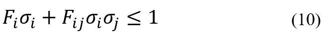
According to the above relation, the Tsai-Wu criterion predicts composite failure when the value of the relation becomes equal to one.
If you want to learn how to do damage analysis in composite pressure vessels, we recommend to get the tutorial below. There is a bonus lesson in this tutorial (Lesson 7) that tells you the difference between using python and Abaqus GUI so you can decide which method is the best for your needs. Interesting, isn’t it?
4.2. Puck Failure Criterion
One of the practical criteria for predicting the behavior of composites is the Puck criterion. This criterion can predict various failure modes in composites. The Puck criterion can predict both fiber and inter-fiber failures. Additionally, it can predict different failure modes such as tension and compression. According to experimental results, the Puck criterion is one of the best criteria for predicting failure in composites. However, this criterion is not available by default in Abaqus software, and to use it, you need to utilize the UMAT or VUMAT user subroutines.
5. Composite Pressure Vessel simulation in ABAQUS
As you have understood so far, composite pressure vessels are widely used, so their simulation is highly important. The current package provides you with the opportunity to become fully familiar with these vessels and their simulation methods. In this package, you will gain a comprehensive understanding of the winding methods for pressure vessels and the relevant equations regarding winding angle and shell thickness. Furthermore, the package thoroughly teaches you how to utilize the graphical user interface (GUI) and Python scripting (line by line) for modeling pressure vessels and you will learn how to determine the winding angle and thickness for each element. The use of the UMAT subroutine for implementing the Puck criterion is also covered in this package. Finally, through several workshops, examples of simulating pressure vessels are executed. By completing this package, you will be able to easily simulate any pressure vessel in Abaqus. All the files of this tutorial, including PowerPoint, Python scripts, UMAT subroutine, and Abaqus simulation files, will be provided to you.
6. Composite pressure vessel analysis with Semi-Geodesic winding
So far, you have realized the importance of pressure vessels and become familiar with their applications and types. Additionally, we have discussed some aspects of simulating these vessels. The current package provides you with the opportunity to become fully familiar with semi-geodesic vessels and their simulation methods. However, in this package, you will learn how to write a Python script for automated simulation of this type of vessel. You will also learn how to utilize the Puck criterion for modeling failure in composites. Furthermore, through two workshops, simulating semi-geodesic pressure vessels are executed. All the files of this tutorial, including PowerPoint, Python scripts, UMAT subroutine, and Abaqus simulation files, will be provided to you.
7. Conclusion to Composite Pressure Vessels Design Analysis and Manufacturing
This article focuses on the design, analysis, and simulation of Composite Pressure Vessels (CPVs). These vessels are critical in industries like aerospace and energy storage, where high-pressure containment is necessary without excessive weight.
The importance of this subject lies in the growing need for efficient, lightweight alternatives to traditional metal pressure vessels, driven by performance and safety demands.
The article is divided into several sections. Introduction to Composite Pressure Vessels discusses the material composition and advantages of CPVs, explaining how filament winding and resin fibers are used to create strong, lightweight structures. Design and Simulation Techniques explores the application of Python scripts and Abaqus software in modeling CPV behavior under pressure, highlighting the importance of accurate simulations for structural integrity. Material Selection and Design Considerations focuses on choosing the right composite materials and optimizing their application for durability and performance.
In conclusion, the article demonstrates that CPVs offer significant benefits in weight reduction and pressure tolerance. We also learn that simulation tools, particularly Python and Abaqus, play a vital role in predicting performance and ensuring safety during the design process.
The CAE Assistant is committed to addressing all your CAE needs, and your feedback greatly assists us in achieving this goal. If you have any questions or encounter complications, please feel free to share it with us through our social media accounts including WhatsApp.
Discover the leading composite pressure vessel manufacturers in our latest article, highlighting industry pioneers like NPROXX, known for their advanced hydrogen storage solutions, and Infinite Composites, creators of the ultra-lightweight iCPV tanks.