


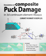
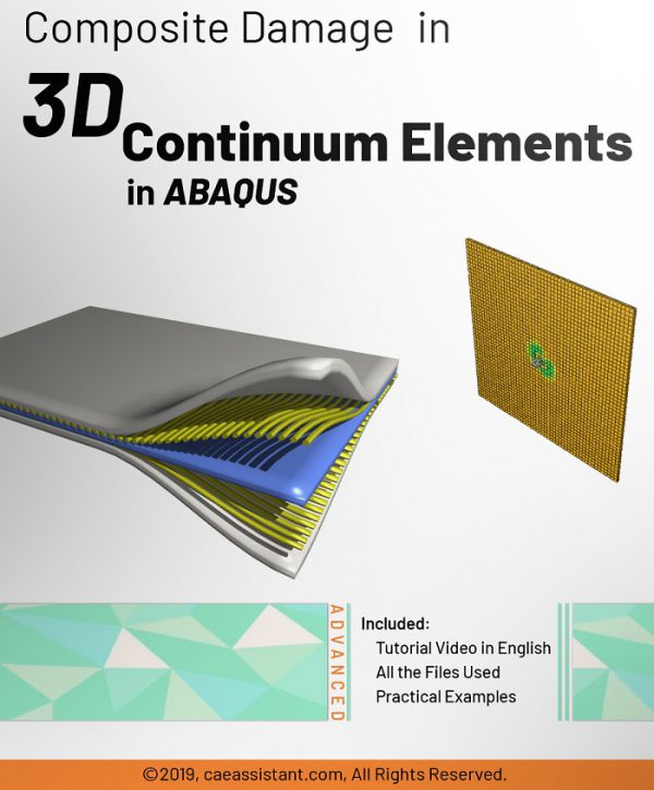
Puck criteria in 3D continuum element
The use of the Puck criterion in simulating composite PUCK damage in 3D continuum elements in Abaqus allows for accurate and efficient predictions of composite failure.
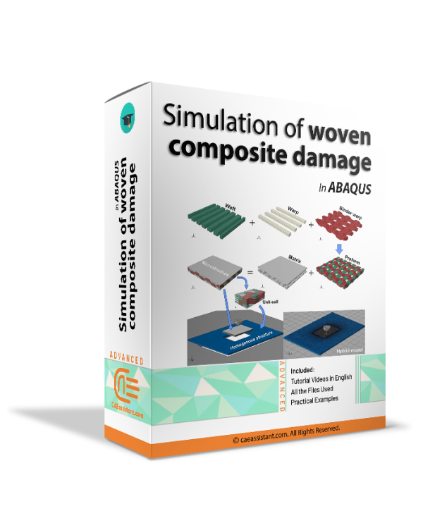
Compared to other failure criteria, such as the Hashin criterion, the Puck criterion has some advantages in predicting composite damage and failure behavior. The Hashin criterion only considers the failure of individual layers or plies in a composite material without considering the interactions between layers.
This training package is designed to provide comprehensive guidance on simulating composite Puck damage in 3D continuum elements using UMAT, VUMAT, and USDFLD subroutines in Abaqus. The package covers a range of different types of failure in composites, including fiber failure, matrix cracking, delamination, and interfacial failure.
By the end of this training package, learners will thoroughly understand how to simulate composite Puck damage in 3D continuum elements using UMAT, VUMAT, and USDFLD subroutines in Abaqus. They will be equipped with the knowledge and skills to accurately predict composite materials’ failure behavior in various engineering applications.
Lesson1: Types of failure in composites
Lesson 1 of this training package covers the types of failure that can occur in composite materials. These include fiber breakage, fiber buckling, matrix tension, matrix compression, and shearing. Understanding these failure modes is essential for predicting the behavior of composites under different loading conditions, as well as for designing and engineering composite materials that can withstand such conditions. The lesson provides an in-depth explanation of each type of failure, along with their causes and effects, and offers practical examples to illustrate how they can occur in a composite material.
Lesson2: Not dependent failure modes criteria in composites
In Lesson 2 of this training package, we explore the criteria for predicting not-dependent failure modes in composites. This section begins with an introduction to these criteria and their importance in predicting the behavior of composite materials. The lesson then covers three widely used failure criteria: The Tsai-Wu criterion, the Tsai-Hill criterion, and the Hoffman criterion. These criteria are used to predict the onset of failure in composite materials that are not dependent on each other, such as fiber breakage and matrix cracking. The lesson explains each criterion, including its assumptions, mathematical formulations, and practical applications. By the end of this lesson, learners will have a thorough understanding of the not-dependent failure modes criteria in composites and how to use them to predict the failure behavior of such materials.
Lesson3: Dependent failure modes criteria in composites
Lesson 3 of this training package focuses on the criteria for predicting dependent failure modes in composites. This section begins with an introduction to these criteria and their importance in predicting the behavior of composite materials. The lesson then covers two types of failure criteria: non-interactive and interactive. Non-interactive criteria, such as the Maximum Strain and Maximum Stress criteria, are used to predict the failure of individual layers or plies in a composite material. Interactive criteria, such as the Hashin, Puck, and Sun-Tao criteria, are used to predict the interaction between layers or plies and the onset of failure in composite materials. The lesson comprehensively explains each criterion, including its assumptions, mathematical formulations, and practical applications.
Lesson4 : The most practical damage criteria of composites
The Puck criterion is a widely used damage-based criterion for predicting the onset and progression of damage in composite materials. The Puck criterion considers both fiber and matrix failures simultaneously, considering the interaction between them. It provides a practical way to predict the onset of damage in composites under various loading conditions, especially in cases where fiber and matrix failures occur simultaneously. Additionally, the Puck criterion is relatively easy to implement using Abaqus subroutines, making it a practical and efficient way to simulate composite PUCK damage.
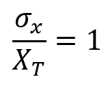
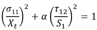
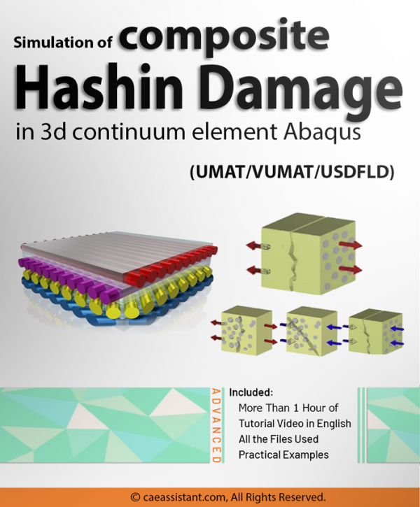
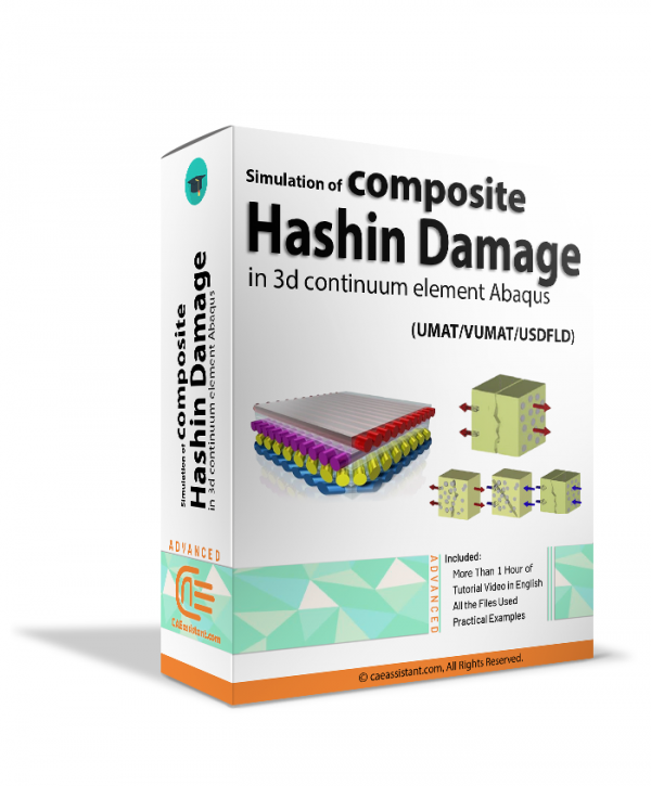
1. Fiber failure under tension
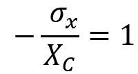
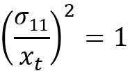
2. Fiber failure under compression
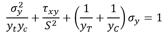
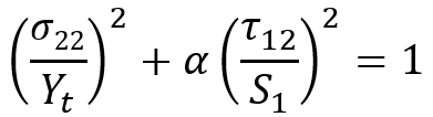
3. Matrix failure
Additionally, the Puck criterion is a damage-based criterion, which means it can predict the progression of damage in composites and provide a more accurate estimate of the remaining strength of the material. Therefore, the proper selection and use of the Puck criterion can play a significant role in accurately predicting composite materials’ damage and failure behavior, making it a preferred choice over other failure criteria in many cases.
The Hashin criterion accounts for both tension and compression failure modes in the composite material, including different failure modes in the matrix and fiber directions. It also considers the effect of fiber volume fraction and orientation on the failure behavior of composites. The Hashin criterion has been widely used to predict the failure behavior of composite materials under complex loading conditions, and it is included in many commercial software packages for composite analysis.
1. Fiber failure under tension ![]()
2. Fiber failure under compression![]()
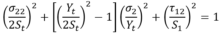
3. Matrix failure under tension![]()
4. Matrix failure under compression![]()
Workshop 1: Simulation of composite Puck damage in 3d continuum element in Abaqus with UMAT
This workshop focuses on simulating composite Puck damage in 3D continuum elements in Abaqus using the UMAT Puck subroutine. The lesson begins with a flowchart of the UMAT Puck subroutine, which outlines the steps needed to simulate the damage behavior of composites using this subroutine. The lesson then covers how to write the UMAT Puck subroutine line by line, providing a detailed explanation of each line and its function.
Finally, the workshop provides learners with a hands-on experience in simulating composite Puck damage in 3D continuum elements using the UMAT Puck subroutine. The workshop guides learners through the steps needed to write the UMAT Puck subroutine, validate it using the Abaqus standard solver, and simulate the damage behavior of composites under different loading conditions.
Workshop 2: Simulation of composite Puck damage in 3d continuum element in Abaqus with VUMAT
This workshop focuses on the simulation of composite Puck damage in 3D continuum elements in Abaqus using the VUMAT Puck subroutine. The VUMAT subroutine is more versatile than UMAT, and it can handle more complex material models, such as viscoelasticity and damage evolution.
Once the VUMAT Puck subroutine is written, the lesson covers how to validate it using Abaqus explicit solver. This involves running simulations on composite materials and comparing the predicted damage behavior to experimental data. The validation process is important to ensure that the VUMAT Puck subroutine provides accurate predictions of the damage behavior of composites under different loading conditions.
The VUMAT Puck subroutine provides a more advanced and versatile method for simulating composite damage compared to the UMAT Puck subroutine. However, writing and implementing in Abaqus requires a higher level of programming skills.
Workshop 3: Simulation of composite Puck damage in 3d continuum element in Abaqus with USDFLD
This workshop covers the simulation of composite Puck damage in 3D continuum elements in Abaqus using the USDFLD Puck subroutine. The lesson begins with a flowchart of the USDFLD Puck subroutine, which outlines the steps needed to simulate the damage behavior of composites using this subroutine. Once the USDFLD Puck subroutine is written, the lesson covers how to validate it using Abaqus standard solver.
By the end of this workshop, learners will have a comprehensive understanding of how to simulate composite Puck damage in 3D continuum elements using the USDFLD Puck subroutine in Abaqus. They will also have practical experience in writing and validating the subroutine, making it a useful tool for predicting the damage behavior of composite materials in various engineering applications.
read more: ddsdde abaqus umat
The Abaqus user subroutine allows the program to be customized for particular applications unavailable through the main Abaqus facilities. You should write a user subroutine if you could not run your analysis by ABAQUS built-in models for materials, loads, properties, elements, etc. for example, if you need to model a user-defined nonlinear stress-strain relation, which is not provided by Abaqus, then look for UMAT user subroutine. A more simple subroutine is USDFLD, which allows the creation of user-defined parameters. If it is your first time writing a subroutine like UMAT, VUMAT or USDFLD please read the Start Writing an Abaqus Subroutine: Basics & Recommendations article. After reading this post and watching this tutorial’s demo video, you will definitely decide to save time in Abaqus modelling and get this training package. If you have questions, ask here on our live chat on the left.
It would be useful to see Abaqus Documentation to understand how it would be hard to start an Abaqus simulation without any Abaqus tutorial. If you are working on Abaqus composite damage and need resources about composite FEM simulation, click on the Abaqus composite analysis page to get more than 20 hours of video training packages of composite materials simulation.
Lorenzo –
For simulating complex composite failure modes such as mixed-mode progressive damage and interactive failure, more accurate methods such as cohesive zone modeling or higher-order finite element methods may be more appropriate than the Puck criterion.
luka –
It would be helpful to include more information about the level of expertise required to fully benefit from this training package .These subroutines require strong programming skills in languages such as Fortran and C++, as well as a deep understanding of finite element analysis.