Showing 1–24 of 160 results

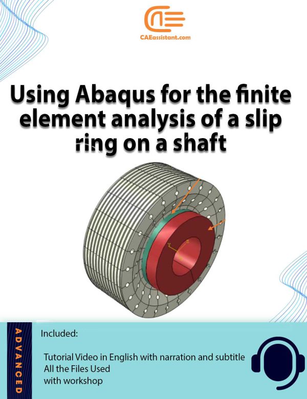
Abaqus shaft slip ring simulation | Using Python scripts for parametric analysis

 270.0
The shaft slip ring is a crucial component enabling the transfer of power and signals in rotating systems. So, this tutorial delves into the intricate Abaqus shaft slip ring analysis. It focuses primarily on the mechanical aspects, offering insights into displacement, stress fields, and strains through the shaft analysis Abaqus model. The tutorial utilizes parametric modeling and Python scripting for the Abaqus shaft slip ring simulation. So, it enables you to optimize geometric parameters, material properties, and loading conditions, enhancing efficiency in modeling processes. It addresses complexities such as creep behavior and material interactions, providing a comprehensive approach tailored for realistic simulations. The tutorial meets various project requirements, supporting them with practical examples and adaptable simulation files.

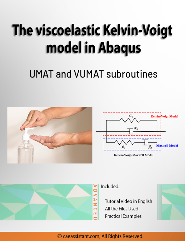
Abaqus Kelvin Voigt Viscoelastic Simulation Using UMAT and VUMAT Subroutines

 270.0
A viscoelastic material exhibits characteristics of both solids and fluids when subjected to stress. This distinct behavior makes them useful in various applications. To use viscoelastic materials in various applications, we need to predict their behavior under different loading conditions. This tutorial discusses in detail how numerical methods address this matter (Abaqus kelvin voigt viscoelastic). The Kelvin-Voigt model describes viscoelastic behavior using a spring and a damper in parallel (kelvin voigt model abaqus). It effectively predicts creep, simulates material responses to impacts, and determines viscoelastic properties of materials like foams, rubbers, and biological tissues. Despite its strengths, it has limitations in describing stress relaxation. This tutorial focuses on implementing the Kelvin-Voigt model in Abaqus CAE using UMAT and VUMAT subroutines. While these subroutines are powerful, they require Fortran knowledge, posing a challenge. To assist, the tutorial provides a step-by-step guide on reviewing the model's formulation and writing the subroutines for both standard and explicit solvers. The tutorial demonstrates capturing damage in a problem, but the results are general, such as stress and displacement. You can customize the subroutine for your models and extract specific results without significant difficulty.

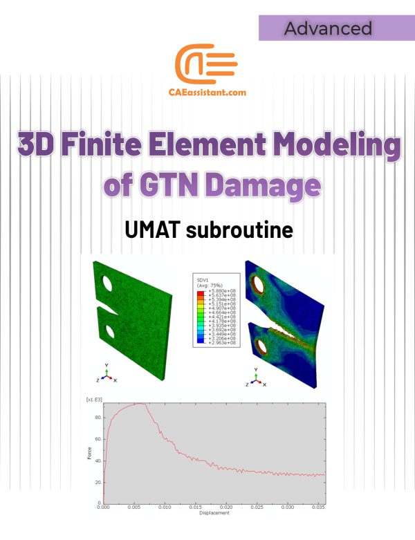
3D Simulation of Gurson-Tvergaard-Needleman (GTN) Damage Model

 190.0
The GTN (Gurson-Tvergaard-Needleman) damage model is a robust continuum damage model used to simulate ductile fracture in materials. It accounts for porosity, a key damage parameter, to predict material behavior under various loading conditions. The model's benefits include comprehensive fracture analysis, accurate damage prediction, versatility, and enhanced simulation capabilities. Despite these advantages, implementing the GTN model in software like Abaqus (GTN model Abaqus) is challenging. It is due to the need for custom subroutines, such as VUMAT. However, writing the subroutine requires proficiency in Fortran programming and an understanding of finite element analysis. This project provides a detailed guide for using the VUMAT subroutine to define the GTN model in Abaqus. It addresses challenges like high computational costs and the need for extensive experimental data. The tutorial demonstrates the model's application in material design, failure analysis, structural integrity assessment, research and development, and manufacturing process simulation. By exploring stress distribution, nodal temperatures, and displacement fields, the project aims to enhance the understanding and predictive capabilities of the GTN damage model.

Viscoplasticity Abaqus Simulation Using UMAT Subroutine | Perzyna Viscoplastic Model

 270.0

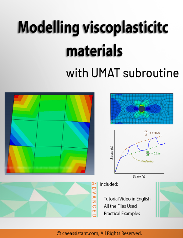
Viscoplasticity describes the rate-dependent inelastic behavior of materials, where deformation depends on both stress magnitude and application speed. This concept is crucial in many engineering applications, such as designing structures under dynamic loads, modeling soil behavior during earthquakes, and developing materials with specific mechanical properties. Viscoplasticity Abaqus simulation, especially using Abaqus with UMAT subroutines, are vital for understanding, predicting, and optimizing the behavior of viscoplastic materials. This tutorial focuses on implementing the Perzyna viscoplasticity model in Abaqus. The Perzyna viscoplastic model, a strain rate-dependent viscoplasticity model, relates stress to strain through specific constitutive relations. This involves defining plastic strain rate based on stress state, internal variables, and relaxation time. The tutorial provides general UMAT codes for viscoplastic analysis, yielding results like stress fields essential for various engineering applications. These simulations help in predicting permanent deformations, assessing structural failure points, and analyzing stability under different loads, benefiting fields such as aerospace, automotive, civil engineering, and energy.

Abaqus User element tutorial | UEL advanced level

 270.0
(3)
User element (UEL) subroutine (user-defined element) is the highest level of a subroutine that Abaqus offers to its users. This subroutine allows the user to program the basic building block of a finite element simulation. This subroutine becomes very powerful when the user wants to implement a type of element that is not available in Abaqus. Using this subroutine, user can define different types of shape functions, introduce element technology that is not available in Abaqus, or simulate multiphysical behavior that is not possible otherwise. This Abaqus user element tutorial package will give a brief introduction to the user element subroutine followed by theory and algorithm to write subroutine small strain mechanical analysis. First, we will highlight the UEL element stiffness matrix and element residual vector which are to be programmed in the first example. We will also cover shape functions and numerical integration. Next, we’ll talk about UEL inputs and outputs. The first example contains the detailed development procedure of a general-purpose subroutine for 2D plane-strain and 3D simulations using triangular, quadrilateral, tetrahedral, and hexahedral type of elements with reduced and full integration scheme. The second example demonstrates the procedure to build UEL-compatible model in Abaqus/CAE. It also demonstrates how to apply complicated boundary conditions with UEL as well as perform Abaqus analysis on structures which has standard and user elements. As an outcome, user can write their own UEL subroutine afterwards using this program as template.

Pultrusion Crack Simulation in Large-Size Profiles | Pultrusion Abaqus

 250.0
(10)

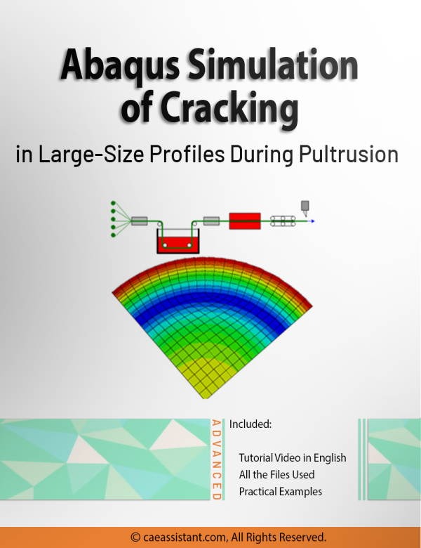
Pultrusion is a crucial task for producing constant-profile composites by pulling fibers through a resin bath and heated die. Simulations play a vital role in optimizing parameters like pulling speed and die temperature to enhance product quality and efficiency. They predict material property changes and aid in process control, reducing reliance on extensive experimental trials. However, simulations face challenges such as accurately modeling complex material behaviors and requiring significant computational resources. These challenges underscore the need for precise simulation methods to improve Pultrusion processes. This study employs ABAQUS with user subroutines for detailed mechanical behavior simulations, including curing kinetics and resin properties. Key findings include insights into crack formation (pultrusion crack simulation), material property changes, and optimization strategies for enhancing manufacturing efficiency and product quality. This research (pultrusion Abaqus) provides practical knowledge for implementing findings in real-world applications, advancing composite material production.

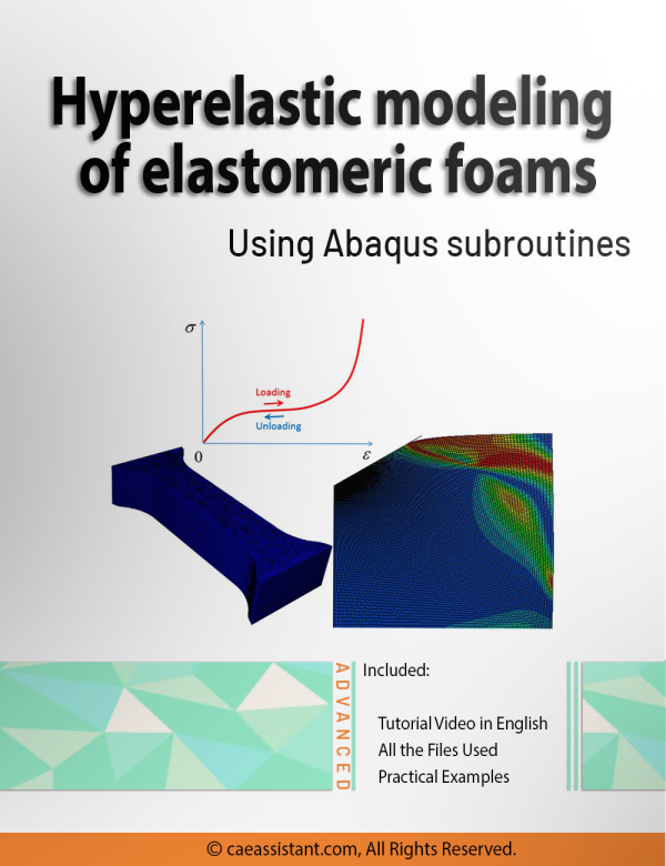
Elastomeric Foam Simulation Using Abaqus Subroutines

 270.0
This study focuses on modeling the mechanical behavior of open-cell, isotropic elastomeric foams. It is essential for applications in materials science and engineering. The project offers insights into designing customized elastomeric foam materials tailored for impact protection in automotive, sports equipment, and aerospace industries. Numerical simulations, using software like Abaqus, enable the prediction of complex behaviors such as hyperelasticity and viscoelasticity under various loading conditions. This finite element analysis of elastomers includes theoretical formulations for hyperelastic constitutive models based on logarithmic strain invariants, crucial for accurately describing large deformations. Practical benefits include the implementation of user-material subroutines in Abaqus, facilitating future extensions to incorporate strain-rate sensitivity, and microstructural defects analysis. This comprehensive approach equips learners with theoretical knowledge and practical tools to advance elastomeric foam simulation. Moreover, it enhances their capability to innovate and optimize materials for diverse applications.

Theta Protection Creep Model | Turbine Blade Creep Life Accurate Prediction | Creep Failure in Turbine Blades

 250.0
(10)

Creep is one of the most significant failure modes in many components where the working temperature and stresses are high for a prolonged period of time. Existing creep models in commercial analysis software like Abaqus are not adequate to model all stages of creep namely – primary, secondary, and tertiary stages. Theta projection method is a convenient method proven to predict all stages of creep, especially the tertiary stage where strain rates are high leading to internal damage and fracture. The aim of the project is to develop a user subroutine for Abaqus to model creep in components using the Theta projection method. The constitutive model for the Theta projection method based on the accumulation of internal state variables such as hardening, recovery, and damage developed by (R.W.Evans, 1984) is adopted to compile a Fortran code for the user subroutine. The user subroutine is validated through test cases and comparing the results with experimental creep data. Creep analysis of a sample gas turbine blade (Turbine Blade Creep) is then performed in Abaqus through the user subroutine and the results are interpreted.

Results of test cases validate the accuracy of the Theta Projection Method in predicting all primary, secondary, and tertiary stages of creep than existing creep models in Abaqus (Creep Failure in Turbine Blades). Results at interpolated & extrapolated stress & temperature conditions with robust weighted least square regression material constants show the convenience in creep modeling with less input data than existing models. The results of creep analysis not only predicted the creep life but also indicated the internal damage accumulation. Thus, creep modeling of components through the user subroutine at different load conditions could lead us to more reliable creep life predictions and also indicate the regions of high creep strain for improvements in the early stages of design.

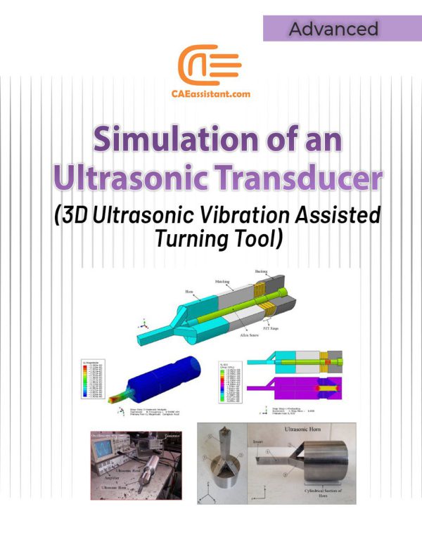
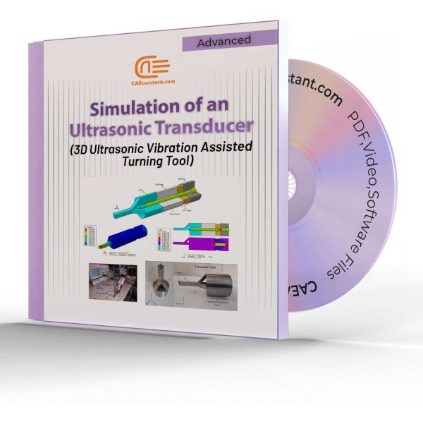
Simulation of an Ultrasonic Transducer (3D Ultrasonic Vibration Assisted Turning Tool)

 190.0

Since the invention of ultrasonic vibration assisted turning, this process has been widely considered and investigated. The reason for this consideration is the unique features of this process which include reducing machining forces, reducing wear and friction, increasing the tool life, creating periodic cutting conditions, increasing the machinability of difficult-to-cut material, increasing the surface quality, creating a hierarchical structure (micro-nano textures) on the surface and so on. Different methods have hitherto been used to apply ultrasonic vibration to the tip of the tool during the turning process. In this research, a unique horn has been designed and constructed to convert linear vibrations of piezoelectrics to three-dimensional vibrations (longitudinal vibrations along the z-axis, bending vibrations around the x-axis, and bending vibrations around the y-axis). The advantage of this ultrasonic machining tool compared with other similar tools is that in most other tools it is only possible to apply one-dimensional (linear) and two-dimensional (elliptical) vibrations, while this tool can create three-dimensional vibrations. Additionally, since the nature of the designed horn can lead to the creation of three-dimensional vibrations, there is no need for piezoelectric half-rings (which are stimulated by a 180-phase difference) to create bending vibrations around the x and y axes. Reduction of costs as well as the simplicity of applying three-dimensional vibrations in this new method can play an important role in industrializing the process of three-dimensional ultrasonic vibration assisted turning.

In this example, how to model all the components of an ultrasonic transducer and its modal and harmonic analysis are taught in full detail.

Abaqus convergence tutorial | Introduction to Nonlinearity and Convergence in ABAQUS

 120.0

This package introduces nonlinear problems and convergence issues in Abaqus. Solution convergence in Abaqus refers to the process of refining the numerical solution until it reaches a stable and accurate state. Convergence is of great importance especially when your problem is nonlinear; So, the analyst must know the different sources of nonlinearity and then can decide how to handle the nonlinearity to make solution convergence. Sometimes the linear approximation can be useful, otherwise implementing the different numerical techniques may lead to convergence.

Through this tutorial, different nonlinearity sources are introduced and the difference between linear and nonlinear problems is discussed. With this knowledge, you can decide whether you can use linear approximation for your nonlinear problem or not. Moreover, you will understand the different numerical techniques which are used to solve nonlinear problems such as Newton-Raphson.

All of the theories in this package are implemented in two practical workshops. These workshops include modeling nonlinear behavior in Abaqus and its convergence study and checking different numerical techniques convergence behavior using both as-built material in Abaqus/CAE and UMAT subroutine.

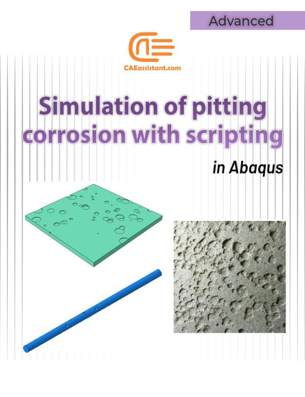
Simulation of pitting corrosion with scripting in Abaqus

 230.0
(3)
Pitting corrosion is a form of extremely localized corrosion that leads to the random creation of small holes in metal. It can occur with random sizes and distributions, typically modeled as conical or cylindrical shapes. This type of corrosion reduces the strength of structures and increases stress concentration. So, it can lead to various destructive effects such as pipes bursting and reduced resistance to internal pressure. By pitting corrosion simulation, you can assess how corrosion affects stress, vibration, heat transfer, and other factors. This is crucial for enhancing the durability and safety of structures such as storage tanks, shafts, tubes, pipes, and other industrial components. This tutorial includes two scripts for pitting corrosion analysis. They help you to conduct Abaqus pitting corrosion simulation for different examples including a simple plate and a shaft.

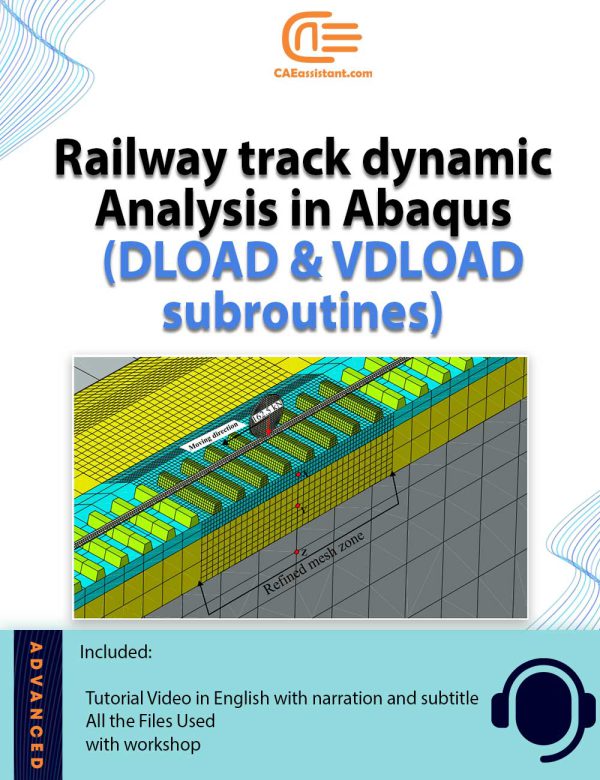
Dynamic Response of Ballasted Rail Track Under a Moving Load

 190.0

Railway tracks are subjected to moving loads of trains and this causes vibration and degradation of the track. The judgment of these vibrations is important to design the railway tracks. The design involves the permissible speed of trains and the maximum axle load of the train. The model given here creates a 3D geometry of a railway track and applies a moving load in the form of a wheel. A user can change the speeds and the properties of the material including geometry as per their needs.

Continuously Reinforced Concrete Pavement (CRCP) Cracking Analysis

 210.0
(1)

The increasing adoption of continuously reinforced concrete pavement (CRCP) in highway pavement design is driven by its demonstrated superior performance. Critical to evaluating the long-term effectiveness of CRCP is the understanding of early-age cracks (CRCP crack analysis), which has garnered significant interest from highway departments. This Abaqus Continuously reinforced concrete pavement modeling project aims to establish precise design parameters for CRCP and analyze the formation of crack patterns. By accounting for stress factors such as environmental conditions and CRCP shrinkage modeling, the project offers valuable insights into predicting the likelihood of crack initiation and propagation within the concrete slab. These insights are instrumental in enhancing the durability and performance of CRCP structures, thus advancing the efficiency and effectiveness of highway infrastructure.

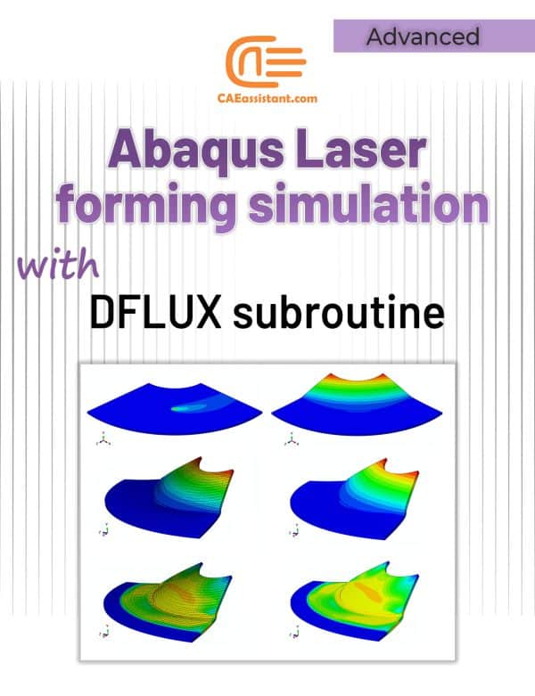
Laser forming simulation tutorial in Abaqus

 120.0
(1)
The laser forming process is performed by applying thermal stresses to the workpiece surface by heating the surface with a laser beam. These internal stresses induce plastic strains in the part resulting in local elastic-plastic deformation (Laser-induced plastic deformation). In this laser forming simulation tutorial the DFLUX subroutine is used to apply heat flux (Gaussian heat distribution) dependent on location and time in finite element simulation. For example, the linear heating processes of laser forming and welding (with a slight simplification) can be simulated by this subroutine. In the linear heating process, by applying heat flux to the surface of a sheet, a thermal gradient is created in its thickness. This thermal gradient causes permanent deformation of the sheet. To simulate the laser forming process, it is necessary to apply a time and location-dependent heat flux to the sheet. In this type of loading, a heat flux is applied on the plate, which is defined using the DFLUX subroutine, including the laser power, movement speed, beam diameter, absorption coefficient, and laser movement path according to the designed experiments (Laser forming process parameters). To verify this Abaqus laser forming simulation, the simulation results and experimental results of sheet deformation (U) are compared. The displacement of the sheet in the simulation is in good agreement with the experimental results.

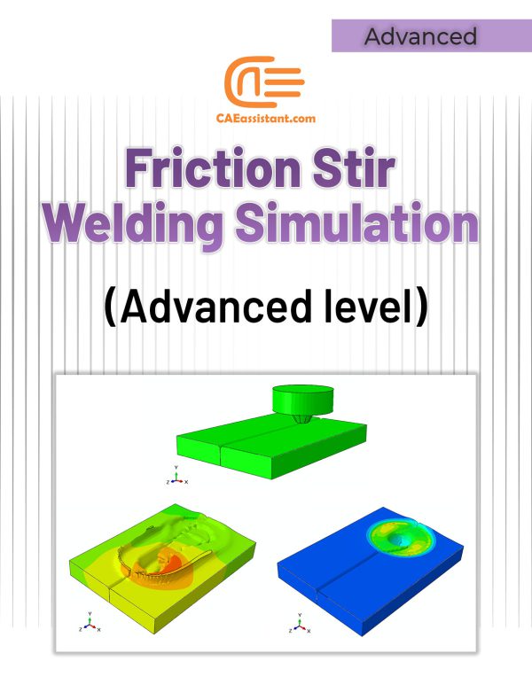
Friction Stir Welding simulation Tutorial | FSW Advanced level

 100.0
(1)
Friction stir welding (FSW) involves complex material flow and plastic deformation. Welding parameters, tool geometry, etc., have important effects on the material flow pattern, heat distribution, and eventually on the structural evolution of the material. In an Abaqus friction stir welding example, the rotational movement of the tool and its friction in contact with the workpiece causes heat generation, loss of strength, and an increase in material ductility around the tool. The feeding movement of the tool causes the material to transfer from the front of the tool to the back of it, and eventually leads to a join. Therefore, heat plays an important role in this process, and parameters such as rotational speed, tool feeding speed, tool geometry, and others, all somehow have a significant impact on controlling the amount of incoming heat, the disturbance and flow pattern of the material, the evolution of the microstructure, and the quality of the resulted weld. This friction stir welding example simulation tutorial shows you how to simulate the Abaqus FSW simulation process in such a way that you can accurately predict the effect of all relevant parameters on the process. In most of the implemented projects, welding mud, and welding defects (welding overfills and overlaps, weld gaps) are not visible and predictable; however, in this simulation, these cases are visible. This project is designed to enhance participants' understanding of how to accurately simulate the FSW process to see the weld's general appearance.

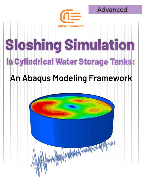
Sloshing Simulation in Cylindrical Water Storage Tanks: An Abaqus Modeling Framework

 120.0
(1)
Liquid storage tanks have many applications in water supply systems and industrial environments. However, seismic damages to these tanks present significant challenges. One of the well-known damages observed in tanks during earthquakes is roof fracture caused by liquid sloshing. Sloshing is a phenomenon that liquid surface moves during seismic events. In this project, we used ABAQUS for the sloshing simulation in ground-supported cylindrical tanks. The tank experiences the acceleration of the El-Centro earthquake. The Abaqus sloshing simulation involves the calculation of Rayleigh damping factors and natural frequencies, employing the ALE meshing technique, and incorporating hourglass controls in Abaqus. We have suggested two ways for the tank sloshing simulation: one involves assigning a low viscosity to the water, and the other is applying Rayleigh damping factors with the assumption of an inviscid fluid. For verification, we modeled a water tank and compared the results with those obtained in the following paper: “Parametric study on the dynamic behavior of cylindrical ground-supported tanks”

Cold Forming Simulation Using Abaqus CAE | Residual Stress Analysis

 59.0
(1)
Have you ever heard of cold forming process? It refers to the reshaping of metals into desired forms at room temperature. It suits well for parts requiring high precision and a good surface finish.  While cold forming offers many advantages, it is important to consider the potential for residual stresses within the material. The residual stresses in cold-formed components can influence their behavior, potentially affecting the quality of the final product. Experimentally measuring these stresses can be challenging. Numerical simulations offer a solution for cold forming residual stress analysis. Among the available numerical methods, Abaqus cold forming simulation has gained significant attention from researchers and practitioners. This training explores Abaqus cold forming analysis in detail. It includes three workshops that cover different steps in the cold forming process. For validation purposes, we have compared the results for the numerical simulation of cold forming with a reference solution for each workshop.

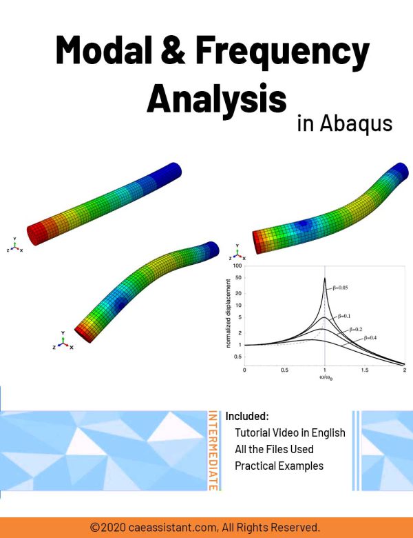
Modal and Frequency Analysis in Abaqus | Abaqus modal Analysis

 70.0
Modal analysis is a technique used to understand how structures and systems vibrate when subjected to forces. It identifies natural frequencies, which are frequencies at which a system vibrates without external excitation, and mode shapes, representing unique patterns of motion. Engineers use modal analysis simulation to design systems resistant to unwanted vibrations, preventing resonance and potential damage. Frequency response analysis evaluates a structure's reaction to specific excitations across varying frequencies, aiding in design optimization to mitigate fatigue damage caused by vibrations. In Abaqus software, Abaqus modal analysis identifies natural frequencies (Abaqus natural frequency) and mode shapes, while frequency response analysis predicts a structure's response to excitation across a frequency range. In Abaqus modal analysis tutorial package, there are several modal analysis examples (modal analysis example): Workshop 1 analyzes the natural frequency of a water transfer tube to predict resonance occurrence or potential issues from vibrations. Workshop 2 simulates the dynamic analysis of a frame under a sudden load, determining modes, natural frequencies, and transient dynamic response. Workshop 3 simulates free and forced vibrations of a wire under harmonic excitation, examining resonance phenomena with preloading and spring-damper configurations. These workshops demonstrate practical applications of modal and frequency response analyses in structural dynamics simulation and design.

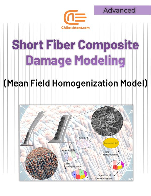
Short fiber composite damage (Mean Field Homogenization Model)

 220.0
(9)
Short-fiber reinforced thermoplastics, popular due to their strength, lightness, and cost-effectiveness, are often manufactured using injection molding to create complex parts with dispersed short fibers. However, failure in these materials is complex, involving mechanisms like fiber cracking and plastic deformation. Current models for damage and failure are either macroscopic or simplified. A new method tackles this challenge by evaluating stiffness using continuum damage mechanics with a multistep homogenization approach. This new method is called “Mean Field Homogenization”. This approach involves a two-stage process: first, the fibers are split into groups (grains). Then, mean-field homogenization is employed within Abaqus using a UMAT subroutine to average stiffness across these phases, followed by overall homogenization. This use of mean-field homogenization Abaqus simplifies the modeling of the composite's intricate geometry. The method was validated through testing on a distal radius plate. Calibration was achieved through experiments, and the simulation was performed using Abaqus finite element software. It's important to note that the Abaqus short fiber damage mean field homogenization process was implemented within Abaqus through the INP code.

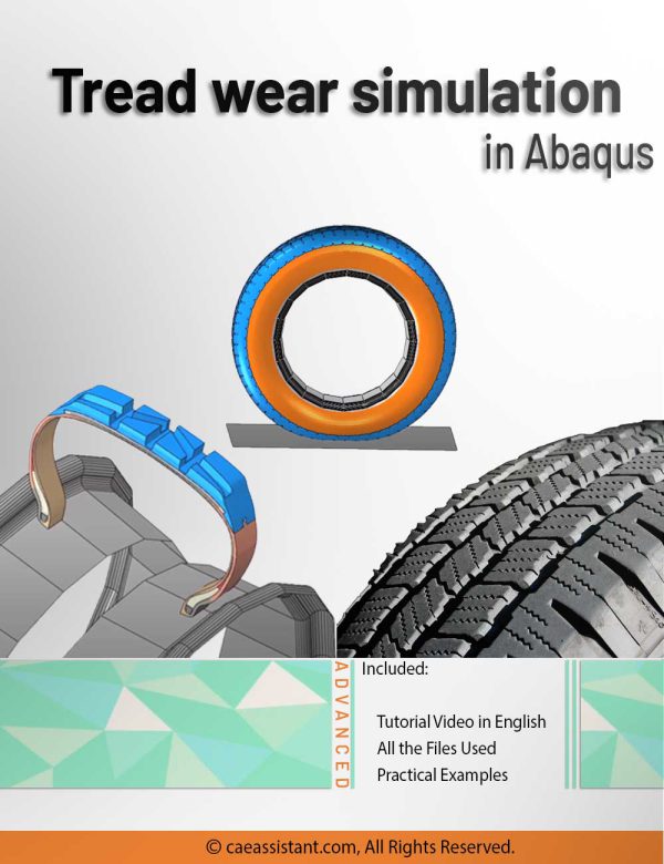
Tread wear simulation in Abaqus

 170.0
(1)
This training package provides a comprehensive exploration of tire tread wear, focusing on its simulation using the UMESHMOTION subroutine in ABAQUS. Tread wear, the gradual erosion of a tire's outer rubber surface, impacts crucial performance aspects like traction and handling. The package elucidates the importance of tread wear simulation, emphasizing safety, performance optimization, regulatory compliance, durability, cost efficiency, environmental impact, and consumer confidence. The UMESHMOTION subroutine, a key element in ABAQUS, is demystified through illustrative examples. Its application in modeling wear processes, specifically employing the Archard model, is highlighted—particularly in node movement specification during adaptive meshing. The workshop within this package delves into simulating tire wear at a speed of 32 km/h over 1000 hours, utilizing the UMESHMOTION subroutine and Archard equations. The tire modeling process, transitioning from axisymmetric to three-dimensional elements, is detailed, considering both slip and non-slip modes of movement. This resource serves as a valuable guide for professionals and enthusiasts seeking to understand and implement effective tread wear simulation techniques using advanced computational tools.

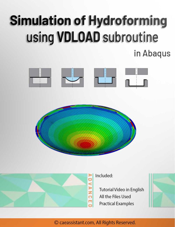
Hydroforming process simulation using VDLOAD subroutine in Abaqus

 170.0
(1)
Dive into the intricacies of hydroforming simulation in Abaqus alongside the VDLOAD subroutine with our comprehensive guide. This tutorial delves into the essence of the Abaqus hydroforming simulation, unraveling the nuances of the hydroforming process simulation. Hydroforming, a specialized metal shaping technique applicable to diverse materials like steel, copper, and aluminum, is explored in depth. In the workshop component, we specifically focus on advanced hydroforming simulation using the VDLOAD subroutine, highlighting its pivotal role in specifying fluid pressure on sheet metal forming. Learn how to apply the Functional Fluid Pressure Loading feature for precise control over fluid pressure dynamics. Additionally, explore the Smooth Amplitude option for defining part displacement seamlessly, without introducing dynamic changes during problem-solving. Conclude your exploration with a comparative analysis of simulation outcomes, dissecting scenarios with and without fluid pressure using Abaqus hydroforming simulation. Engage in discussions on subroutine writing, delving into the intricacies of incorporating Fluid Pressure Loading into your simulations. This guide offers a natural progression through hydroforming and VDLOAD, providing valuable insights for efficient and accurate simulations.

Shape optimization in Abaqus

 150.0
(1)
Shape optimization is employed towards the conclusion of the design process, when the overall structure of a component is established and only minor adjustments are permitted by relocating surface nodes in specific regions. In shape optimization, the displacements of the surface nodes (design nodes) serve as the design variables. The process commences with a finite element model that requires slight enhancements or with a finite element model derived from a topology optimization. In this training package, first, you will learn the concept of optimization and shape optimization in Abaqus. After that, all required settings to do a shape optimization, such as optimization task and design responses will be fully explained. And in the last lesson, you will learn how to create an optimization process and be familiar with the generated files by the shape optimization process.

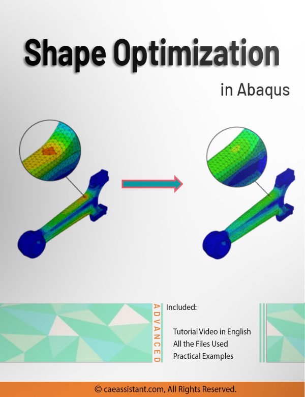
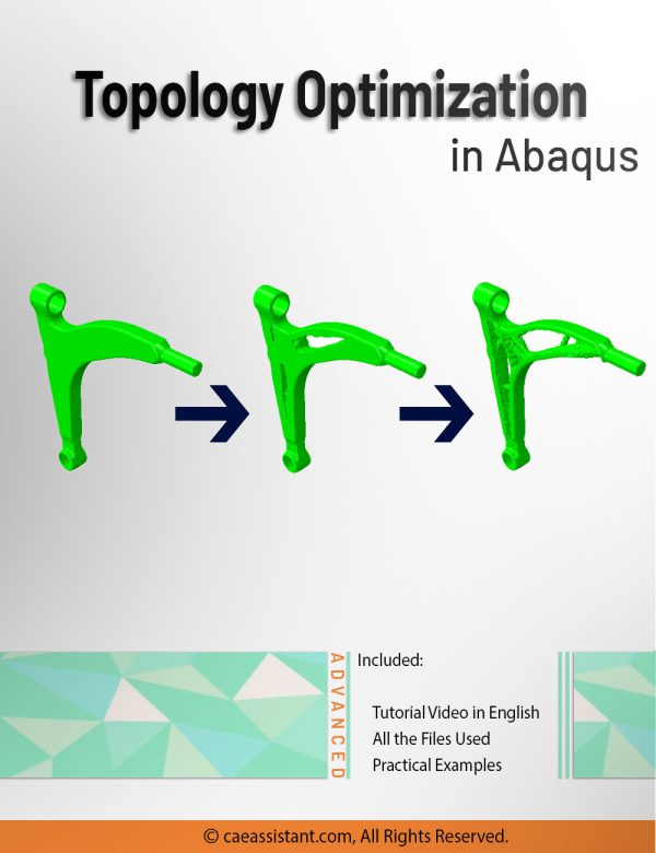
Topology Optimization in Abaqus

 150.0
(2)
Optimization is a fundamental concept used to enhance the effectiveness and efficiency of systems, designs, and decisions. It finds application in various domains, including industrial processes, finance, and communication networks. In engineering, optimization plays a crucial role in improving the design of systems and structures by maximizing performance and minimizing costs, weight, or other parameters. Structural optimization specifically focuses on designing or modifying structures to meet performance criteria while minimizing or maximizing objectives such as strength, weight, cost, or efficiency. The Abaqus software provides comprehensive structural optimization capabilities, including topology, shape, sizing, and bead optimization. This training package primarily focuses on topology optimization. Through the lessons and workshops, you will gain insights into the tips, tricks, and techniques for effectively utilizing topology optimization within the Abaqus software.

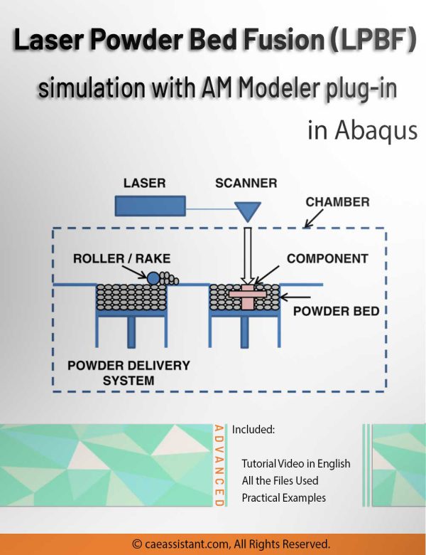
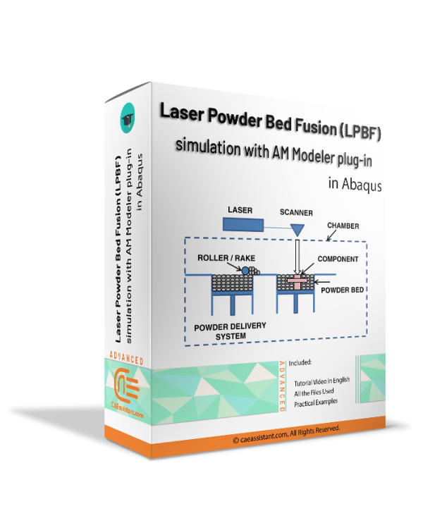
3D printing simulation with Laser Powder Bed Fusion (LPBF) method in Abaqus

 150.0
(1)
3D printing is a process of creating three-dimensional objects by layering materials, such as plastic or metal, based on a digital design. 3D printing simulation involves using software to predict and optimize the printing process, allowing for more efficient and accurate production. This educational package includes two 3D printing modeling methods. The first method is based on the use of subroutines and Python scripting. After an introduction to the 3D printing process, the first method with all of its detail is explained; then, there would be two workshops for this method; the first workshop is for the 3D printing simulation of a gear with uniform cross-section and the second one is for a shaft with non-uniform cross-section. The second method uses a plug-in called AM Modeler. With this plug-in, the type of 3D printing can be selected, and after inserting the required inputs and applying some settings, the 3D printing simulation is done without any need for coding. Two main workshops will be taught to learn how to use this plug-in: "Sequential thermomechanical analysis of simple cube one-direction with LPBF 3D printing method using the trajectory-based method with AM plug-in" and "3D printing simulation with Fusion deposition modeling and Laser direct energy deposition method with AM plug-in".