
Concrete Beams & Columns Analysis by Abaqus: An Introduction

Reinforced concrete columns and beams are the backbone of modern structures, ensuring stability and strength in buildings and bridges. While concrete alone has high compressive strength, it is weak in tension. That’s why reinforcement, typically with steel rebar, is essential to prevent cracking, buckling, and failure under heavy loads. Without proper reinforcement and design, these structural elements can experience severe damage, compromising the safety of an entire structure.
Understanding reinforced concrete column analysis and reinforced concrete beam analysis is crucial for engineers. Columns mainly resist axial compression but can fail due to buckling or crushing, depending on their slenderness and material properties. Beams, on the other hand, experience bending and shear, which creates tension in some areas and compression in others. Engineers use theories like Euler’s buckling formula for concrete column analysis and Euler–Bernoulli beam theory for concrete beam analysis to predict and enhance performance.
This blog explores the analysis and design of reinforced concrete beams and columns. It covers key failure mechanisms, reinforcement strategies, and introduces advanced numerical simulation techniques. Additionally, it discusses finite element analysis of reinforced concrete beams using Abaqus tools such as the Concrete Damage Plasticity (CDP) model, which helps engineers model and predict the structural behavior of reinforced concrete with high accuracy.
|
Simulation of Concrete Beams and columns: CDP in tension & Compression +Damage and results of CDP + 2 Workshops for reinforced beam and column |
Basics of Concrete Beams & Columns simulation + Reinforced concrete beams & columns + Fiber reinforced beams & columns simulation |
Advanced level of Concrete Beams & Columns + Several reinforced techniques for beams and columns + More than 7 Examples |
1. Concrete Column Analysis Fundamentals
Concrete column analysis is an important part of structural engineering. It focuses on how concrete columns perform under different loads. These vertical structures are designed to carry weight, and their strength depends on factors like material properties, shape, and the type of load they bear. The main goal is to ensure the column can safely support the load without failing, maintaining both strength and stability. Therefore, for the analysis of concrete columns, we will examine the following:
- What are columns and concrete columns?
- Design considerations and theories
1.1. Understanding Concrete Columns: Types and Functions
Columns are vertical structural members designed primarily to carry axial loads (compressive forces). In an idealized situation, a column is assumed to be perfectly straight, homogeneous, and free of initial imperfections. However, in practice, every column may have slight deviations, which can affect its stability. Columns can fail under various conditions and buckling is one of the most common. Columns are made of various materials, such as steel columns or concrete columns, which play an important role in construction.
Concrete columns are structural elements made primarily of concrete, often enhanced with steel reinforcement (rebar) to improve tensile capacity and ductility. Unlike slender steel columns that are usually analyzed using Euler’s theory alone, concrete columns are typically “composite” in nature. They combine the high compressive strength of concrete with the tensile strength of reinforcing steel, which provides the necessary resistance to bending and cracking. Concrete columns may vary in shape (rectangular, circular, T-shaped, etc.). These are some concrete columns examples:
- Building Columns: Rectangular or circular reinforced concrete columns are common in multistory buildings where they support the load of floors and roofs.
- Bridge Piers: Often designed as reinforced concrete columns, these elements carry large compressive forces and may include additional design features to account for dynamic loads.

Figure 1: Example of bridge piers that are damaged [Ref]
Unlike slender steel columns that primarily fail by buckling, concrete columns Because usually do not experience tension and are only under pressure, can fail by crushing if they are stocky, or by a combination of crushing and buckling if they are slender. So concrete columns are usually designed based on compressive load and buckling.
1.2. Key Theories in Concrete Column Design
To design columns, it is important to pay attention to the type of loading. Accordingly, the theories used in column design are based on the type of load that the columns bear. Also, in column design, the type of deformation in the columns is very important. In this section, you will learn about two theories that play an important role in the design and analysis of columns.
Note: learn more about these theories with practical examples in finite element analysis software, the Abaqus.
- Euler’s Buckling Theory
Euler was among the first to develop a mathematical model for the lateral instability (buckling) of slender columns. Euler’s theory predicts that when a column is loaded axially, it remains straight up to a critical load; beyond that, even the slightest imperfection will cause it to deflect laterally. The Euler equation for the critical buckling load is given by:
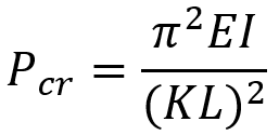
where:
- Pcr is the critical buckling load
- E is the modulus of elasticity of the material
- I is the second moment of area (moment of inertia) of the cross-section
- L is the actual length of the column
- K is the effective length factor (which accounts for end conditions such as pinned, fixed, or free supports).
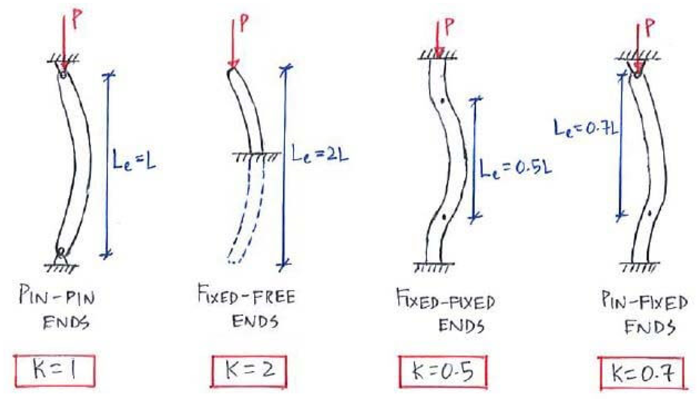
Figure 2: Effective length for various conditions [Ref]
Euler’s equation assumes small deflections, perfect material behavior, and that the load is applied exactly through the centroid. These idealizations make it a powerful tool for understanding buckling in slender columns. If you are interested in buckling and Euler’s theory you can visit our blog, “The A to Z of Buckling: Column Buckling, Buckling Equations, and More” which is a comprehensive blog about buckling.
- Rankine-Gordon equation
Many design approaches such as the Rankine-Gordon equation, use modified formulas to adjust for the imperfections and nonlinearity inherent in concrete. These methods combine Euler’s theory with empirical data to give safer, more realistic estimates of capacity. The Rankine–Gordon equation is an empirical equation used to predict the critical load (or stress) at which a column will fail due to a combination of crushing (material yielding) and buckling. It essentially bridges the gap between two failure modes:
-
- For very short columns: the column reaches its compressive strength, so failure is governed by material crushing.
- For very long columns: Failure is dominated by buckling, as described by Euler’s equation.
🤔Basic tutorial 🧐of finite element modeling of concrete beams and columns from the very beginning.

The Rankine–Gordon equation combines these two into one equation that is applicable across the full range of column slenderness. The equation is written as:
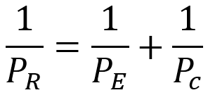
where:
- PR is the critical load.
- PE is the Euler buckling load.
- PC is the crushing load (product of the material’s compressive strength and the cross-sectional area A).
This formulation implies that for short columns (where PE is very high), the failure load PR is close to the crushing load PC, and for slender columns (where PE is low), PR approaches the Euler buckling load PE.
In another form (often used for design in terms of stresses):
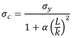
where:
 is the critical stress of the column.
 is the material’s compressive (yield) strength.
- L is the effective length of the column.
- k is the radius of gyration of the column’s cross-section (
 ).
). - α is the Rankine constant, an empirical constant that depends on the material and end conditions.
In summary, the Rankine–Gordon formula is a practical design tool that provides a single expression for predicting column failure across the full range of slenderness ratios, accounting for both material crushing and buckling phenomena.
2. Concrete Beam Analysis Fundamentals
Concrete beam analysis is essential in structural engineering to ensure beams can safely support loads and maintain structural integrity. Unlike columns, which primarily carry axial compression, beams experience bending moments and shear forces, requiring careful design to prevent cracking, deflection, and failure.
For an effective concrete beam analysis, engineers must consider several key factors:
- Types of Loads: Beams are subjected to dead loads, live loads, wind loads, and other forces that influence their structural behavior.
- Beam Cross-Sections: The shape and dimensions of a reinforced concrete beam affect its load-bearing capacity, with common types including rectangular, T-beams, and I-beams.
- Bending and Shear Behavior: Beams develop tensile stress on one side and compressive stress on the other, requiring reinforcement to resist cracking and failure.
- Theoretical Models: The Euler–Bernoulli beam theory provides a foundation for understanding beam deflection and stresses, while the Timoshenko beam theory accounts for shear deformations in shorter, thicker beams.
- Finite Element Analysis (FEA): Advanced tools like Abaqus allow engineers to perform finite element analysis of reinforced concrete beams, simulating their real-world behavior under various loading conditions.
By analyzing these factors, engineers can design reinforced concrete beams that maximize strength, minimize deflections, and enhance durability in bridges, buildings, and infrastructure projects.
2.1. Understanding Concrete Beams: Behavior and Applications
Beams are primarily horizontal structural members designed to carry loads applied perpendicular to their longitudinal axis. When a beam is loaded, it bends (experiences flexure), developing tensile stresses at one surface and compressive stresses at the opposite surface. The behavior of beams under bending is one of the most common problems in structural analysis. While most of the ones we are familiar with are steel beams (usually with an H or T section), concrete beams are also structural members made of concrete, often reinforced with steel (rebar). In a concrete beam, the concrete usually carries the compressive stresses while the embedded reinforcement carries the tensile stresses.
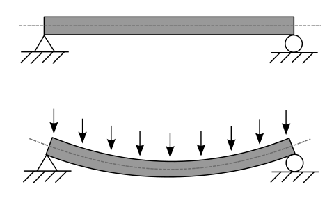
Figure 3: A beam under bending
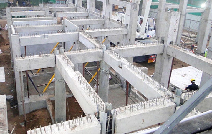
Figure 4: Concrete beams used in the building [Ref]
Beams can come in many different types, both in terms of cross-section and material. As you can see in the next figure, there are different types of beams.
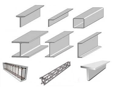
Figure 5: Different types of beams
2.2. Key Theories in Concrete Beam Design
As mentioned in the case of columns, it is also very important to pay attention to the loads applied to the beams in the design of beams. In beam design, unlike columns, bending stresses play a significant role. Many theories examine beams from different points of view, but theories such as the Euler-Bernoulli theory or the Timoshenko theory are very well known. In the next step, we will examine the Euler-Bernoulli theory.
- Euler–Bernoulli beam theory
For analyzing beams, the most widely used theory in beam analysis is the Euler–Bernoulli beam theory. This theory assumes that:
-
- When a beam bends, any cross-section that was originally perpendicular to its neutral axis stays flat and continues to meet the neutral axis at a right angle.
- Deflections are small enough that linear relationships hold.
DO NOT MISS the 🚀ULTIMATE🚀 tutorials on Concrete Beams and Columns: Doubled reinforced, Fiber reinforced, etc.

Under these assumptions, the bending moment M at any section of a beam is related to the curvature (second derivative of deflection w) by:
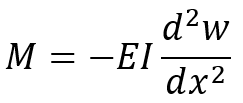
Where:
- E is the Young’s modulus.
- I is the second moment of the area of the beam’s cross-section.
On the other hand, the shear at each section of the beam is calculated as follows:
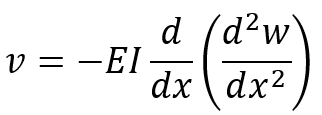
Where v is the shear force.
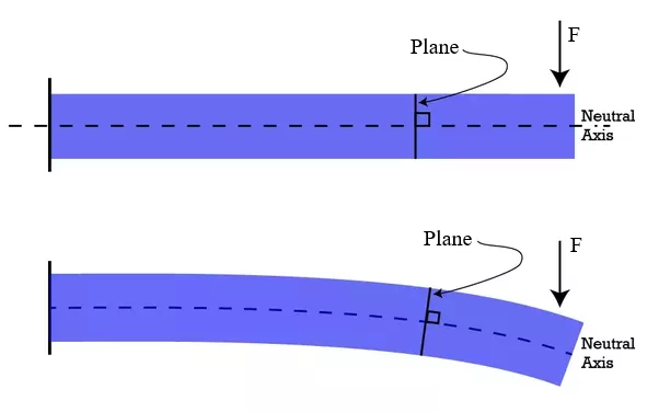
Figure 6: Plane section and neutral axis after bending (Euler–Bernoulli theory) [Ref]
For thicker beams or when shear deformations are significant, Timoshenko beam theory provides a refined model by including shear effects. Timoshenko beam theory is an enhancement of the classical Euler–Bernoulli beam theory. It accounts for shear deformation and rotational inertia effects, which are particularly important in short beams or beams with a low slenderness ratio. Unlike Euler–Bernoulli theory—which assumes that cross-sections remain perpendicular to the neutral axis after bending—Timoshenko’s theory allows these sections to rotate, thus providing a more accurate prediction of deflections and stresses, especially when shear effects cannot be neglected.
3. Beams vs. Columns: Key Structural Differences
While beams and columns can sometimes be made from the same materials and even share similar cross-sectional shapes, their functions and design criteria differ significantly. Now, based on the explanations we gave about columns and beams, we can see their differences summarized in the table below.
| Aspect | Beams | Columns |
| Orientation and Load Type | Horizontal members are designed to resist bending moments and shear forces from loads applied perpendicular to their length. | Vertical members are primarily designed to carry axial compressive loads. |
| Behavior Under Load | Bending induces a linear stress distribution (tension at the bottom, compression at the top) with significant deflections. | Load is carried primarily by compression, with failure governed by buckling or crushing. |
| Design Considerations | Focus on ensuring adequate moment capacity and controlling deflections under service loads. | Involves checking axial capacity, slenderness ratio, and buckling resistance. |
These distinctions are critical; a beam must be designed to flex without excessive deflection or cracking, while a column must be robust against instability.
Which is stronger beam or column?
They can’t be directly compared because beams and columns serve different purposes — beams handle horizontal loads and bending, while columns support vertical loads through compression. But in seismic design, engineers intentionally make columns stronger than beams to follow the “strong column–weak beam” principle. This helps buildings absorb earthquake energy more safely and reduces the risk of collapse.
4. Concrete Beams and Columns: Advantages and Disadvantages
Concrete beams and columns are key elements in most structures. Understanding their pros and cons helps engineers and builders make smarter design decisions. Here’s a quick breakdown:
🟩 Advantages of Concrete Beams and Columns
-
Strong Load Support: Beams carry loads from slabs to columns, while columns transfer those loads to the ground—ensuring stability.
-
Durability: Concrete is highly durable and resistant to fire, pests, and weather, making it ideal for long-lasting structures.
-
Flexibility in Design: Concrete beams and columns can be shaped and sized to fit different architectural and structural needs.
-
Cost-Effective Materials: Reinforced concrete is widely available and relatively affordable compared to other materials like steel.
🟥 Disadvantages of Concrete Beams and Columns
-
Weight: Concrete is heavy, which increases the load on foundations and may require more robust structural support.
-
Cracking and Shrinkage: Without proper design and curing, concrete elements may crack over time.
-
Labor-Intensive: Construction involves formwork, reinforcement, and curing time, which can slow down project timelines.
-
Limited Ductility: Compared to steel, concrete is more brittle and less flexible under stress.
5. Reinforced Concrete Column Analysis: Design Approaches
One of the most important challenges in the design of concrete columns is to increase their strength. There are several ways to increase the strength of a concrete column, including increasing the cross-sectional area, increasing the strength of concrete (material), reducing the effective length of the column, etc. However, the best and most efficient way to increase the strength of concrete columns is to add reinforcements and combine concrete with steel. As you know, reinforced columns are widely used in various structures, including buildings and bridges. Concrete columns usually have very high compressive strength, but they are weak against tension and buckling, so by adding steel reinforcements, the strength of the column against buckling is gradually increased. This approach is key to successful reinforced concrete column analysis, which allows engineers to design more reliable and efficient structures.
To increase the strength of concrete columns, in addition to rebar, other reinforcements can be added, such as various types of fibers like carbon fiber or polymer (or steel) tubes.
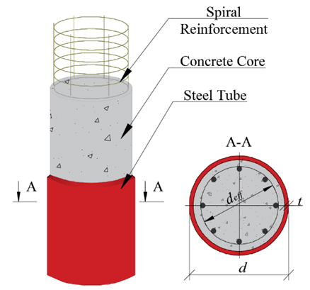
Figure 7: reinforced concrete column by rebar and steel tube [Ref]
5.1. Pros and Cons of Reinforced Concrete Columns
Advantages:
- High Compressive Capacity: Concrete inherently has excellent compressive strength, which is enhanced by steel reinforcement.
- Economy and Availability: Materials (concrete and reinforcing steel) are widely available and can be cost‐effective.
- Weight reduction: In the design of reinforced columns, using theoretical reinforcements such as polymer or metal tubes can reduce the weight of the column.
Disadvantages:
- Fire Resistance: Concrete is naturally fire resistant, which can increase safety, unlike reinforced columns where the reinforcements are less resistant to heat and fire.
- Brittle Failure Risk: By excessively increasing the amount of reinforcement, the column can become increasingly brittle against compressive loads.
- Construction Complexity: Proper reinforcement detailing (placement, cover, and spacing) is critical, and errors during construction can compromise performance.
5.2. Key Design Approaches for Reinforced Concrete Columns
Reinforced concrete column design usually follows an ultimate strength (limit state) approach. Designers use axial load capacity for various reinforcement ratios and concrete strengths to design Reinforced concrete columns.
- Axial Capacity:
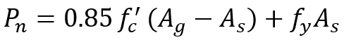
The nominal axial capacity Pn is determined by the contributions of the concrete and the reinforcement. A simplified expression (for a column predominantly in compression) is:
Where:
- Ag is the gross area of the column.
- As is the area of reinforcement.
 is the concrete compressive strength.
 is the yield strength of the steel.
As mentioned, you should also note that sometimes complex loadings lead to bending in the reinforced concrete beams just like other beams, in which case, in addition to the compressive strength and critical buckling force, bending must also be considered in the design, and the stress resulting from it must be added to other stresses.
6. Reinforced Concrete Beam Analysis
As concrete columns, the most cost-effective and efficient way to improve the performance of concrete beams is to use reinforcements. Various reinforcements are used today to combine with concrete, including rebar or steel beams, polymer and fiber reinforcements are also very effective in strengthening concrete. The figure below shows some examples of a combination of a concrete beam reinforced with rebar and a steel beam. In the following, there are some design approaches that would come in handy for reinforced concrete beam analysis.
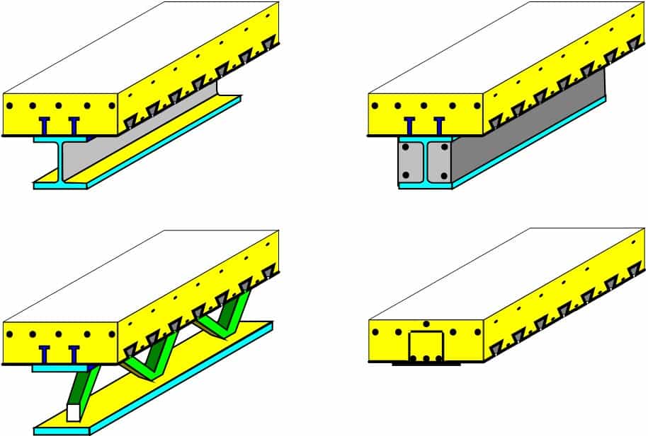
Figure 8: Different types of reinforced concrete beams [Ref]
Design Approach:
For designing reinforced concrete beams, simple beam criteria can also be used, but to model the behavior of reinforced concrete beams as accurately as possible, relations that can model concrete and reinforcement should be used. Usually, to do this, the ultimate strength of the reinforced concrete beam is analyzed.
- Compression Force in Concrete:
At ultimate loads, the concrete’s nonlinear behavior is approximated using an equivalent stress block. The compressive force in concrete is modeled as:
![]()
Where:
-
 is the specified compressive strength of concrete.
- b is the width of the beam.
- a is the depth of the equivalent stress block (often given by
 , that c is the depth to the neutral axis and
  is a factor depending on ).
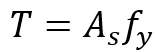
- Tensile Force in Reinforcement:
The tensile force in reinforced concrete beams is calculated from the following equation:
Where:
-
 is the area of tensile reinforcement.
 is the yield strength of the reinforcing steel.
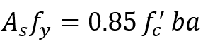
For the design of reinforced concrete beams, at ultimate load, equilibrium requires that compressive and tensile loads must be equal, so:
- Moment Capacity:
On the other hand, the moment capacity must also be considered in the beam design calculations. The design moment capacity is calculated as follows:
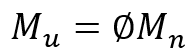
![]() , known as the capacity reduction factor, is used to account for uncertainties in material properties, variations in construction quality, and assumptions in the analysis.
, known as the capacity reduction factor, is used to account for uncertainties in material properties, variations in construction quality, and assumptions in the analysis. ![]() , the nominal moment capacity of the beam (assuming a rectangular section) is calculated as:
, the nominal moment capacity of the beam (assuming a rectangular section) is calculated as:
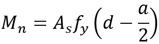
where d is the effective depth from the top of a reinforced concrete beam to the centroid of the tensile steel.
These formulas form the basis of reinforced concrete beam design and allow engineers to size the beam and determine the required reinforcement.
7. Finite Element Analysis of Reinforced Concrete Beams and Columns
As you know, Abaqus is a powerful finite element analysis tool whose high capabilities make it very useful in the Finite Element Analysis of Reinforced Concrete Beams and Columns. In the following sections, we will generally introduce two approaches to simulating concrete columns and beams in Abaqus software, which include the tools available in the software and the UMAT subroutine.
Concrete Damaged Plasticity (CDP)
One of the most important parts of simulating reinforced concrete in Abaqus software is the modeling of its material behavior correctly and accurately. Therefore, accurate modeling of concrete plays a key role in simulations. One of the criteria that Abaqus provides to users for modeling concrete materials and examining the nonlinear behavior of concrete is the concrete damage plasticity (CDP) model. This model considers two main assumptions in the failure mechanism: tensile cracking and compressive crushing. In this model, the behavior of concrete follows the Drucker-Prager failure model. In a way, this model operates based on a reduction in the elasticity level of the model. In the following, we will examine the implementation of this model in Abaqus.
Save your time with eye-opening practical examples to learn CDP in Abaqus modeling reinforced concrete beams and columns
The first step to do this is to select the Concrete Damage Plasticity from the Plasticity submenu in the Properties module.
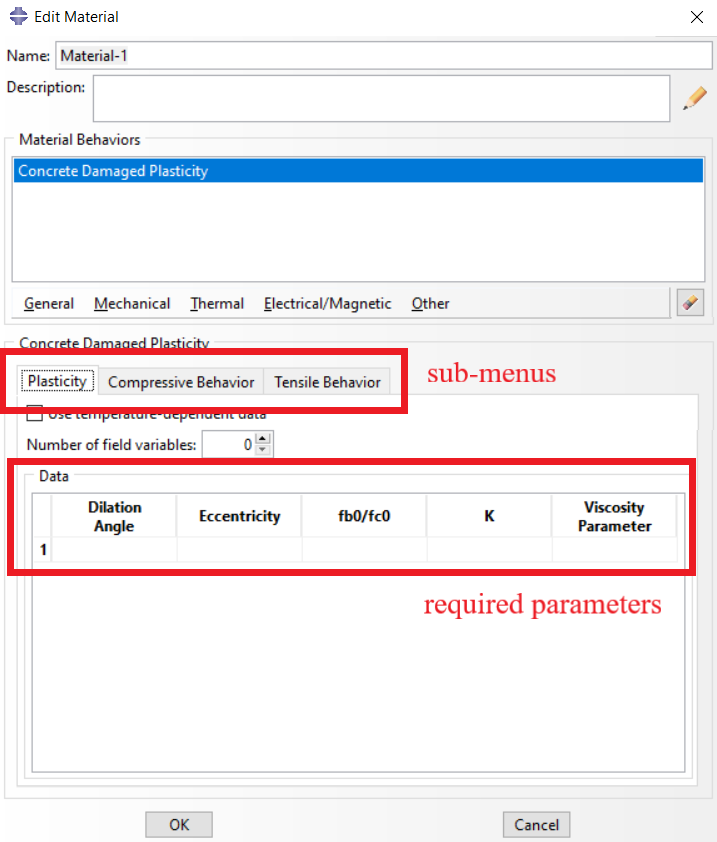
Figure 9: Concrete Damaged Plasticity (CDP) model
As you can see in the figure above, this window consists of three submenus where the user must specify the plastic properties, compressive behavior, and tensile behavior of concrete, respectively. The parameters required to specify the plastic properties are as follows.
- The dilation angle: Describes the plastic strain due to shear stress after the elastic phase.
- Eccentricity: Denotes the eccentricity of the plastic potential surface, as determined by Bazant and Jirasek.
 : The ratio of biaxial to the uniaxial compressive yield stresses
- K: The ratio of the second stress invariant on the tensile meridian to that on the compressive meridian.
- Viscosity parameter: This parameter is used by Abaqus to improve the convergence thread in advanced materials
Also, to determine compressive behavior, you must specify “Yield Stress” and “Inelastic strain”, respectively, and on the other hand, to determine tensile behavior, “Yield Stress” and “Cracking strain” must be specified.
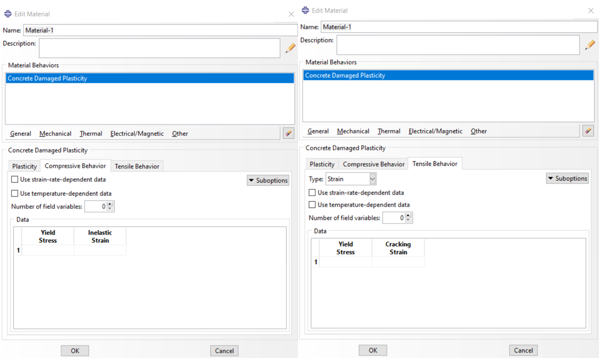
Figure 10: Compressive and Tensile behavior
On the other hand, to model the elastic and plastic behavior of the rebar, determine the complete properties of the rebar, such as the properties of steel, in Abaqus from the Elastic and Plastic submenus. To learn more about the CDP simulation method, you can review and read the “Concrete Damage Plasticity (CDP) in Abaqus” article from our website.
There are other concrete structures as well and you can learn about them and how to simulate them in this blog: “Concrete structure analysis | Abaqus simulation tips“.
UMAT subroutine
The UMAT subroutine is one of the most powerful and widely used subroutines in Abaqus. It is basically designed to allow users to define materials with specific behaviors that are not predicted by Abaqus. Since there are many different types of reinforced concrete (such as carbon fiber reinforced concrete or polymer fiber reinforced concrete) and different theories of concrete damage and reinforcement are available to users (such as the theories mentioned in the previous sections), this subroutine can provide an opportunity for users who either use specific reinforcements or have a new criterion for reinforced concrete beam or column failure.
|
Simulation of Concrete Beams and columns: CDP in tension & Compression +Damage and results of CDP + 2 Workshops for reinforced beam and column |
Basics of Concrete Beams & Columns simulation + Reinforced concrete beams & columns + Fiber reinforced beams & columns simulation |
Advanced level of Concrete Beams & Columns + Several reinforced techniques for beams and columns + More than 7 Examples |