
Here we have presented some users questions about CDP or concrete damage plasticity:
1. CDP analysis
Q: I used the CDP model to create a small solid cubical part. After establishing the necessary boundary conditions, the load is applied. When I check at the stress in my odb file, some of the elements have more stress than the yield stress I entered? Is there an explanation for this?
A: Two things could have happened; either you didn’t enter the CDP parameters correctly, such as units might be wrong or anything else, or when you defined the compressive and tensile behavior, you didn’t control the slope of the diagrams.
Check the link below. In these lessons, you will understand the CDP completely.
Abaqus Tutorial for Beginners (Abaqus Tutorial for Civil Engineering)
2. CDP simulation in Abaqus
Q: In the Abaqus CDP, I’m working with fiber concrete. I had previously modeled the EN 14651 (3-point bending) test and now I was testing my “real” beams. She has longitudinal reinforcement and stirrups, as seen in the photo (figure 1). There are no stirrups in a small test area (I’m dealing with shear). However, regardless of how the material input stresses change, the force-displacement graphs in the post-peak zone show increasing force (Figures 2 and 3).
The supports were positioned in a beam region (without drawing the supports) and the displacement was applied in an RP with “coupling.” Reinforcement can also be found in the “embedded region.” I put it to the test with some random material from a YouTube video, and the strength keeps increasing. Is there something wrong with my model? In addition, the peak force is significantly higher than the experimental data. Figures 4 and 5 show the data from the CDP.
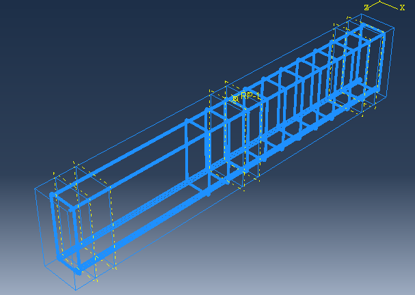
Figure 1
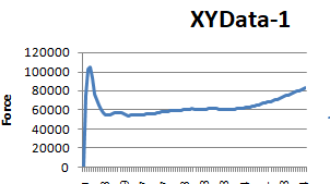
Figure 2
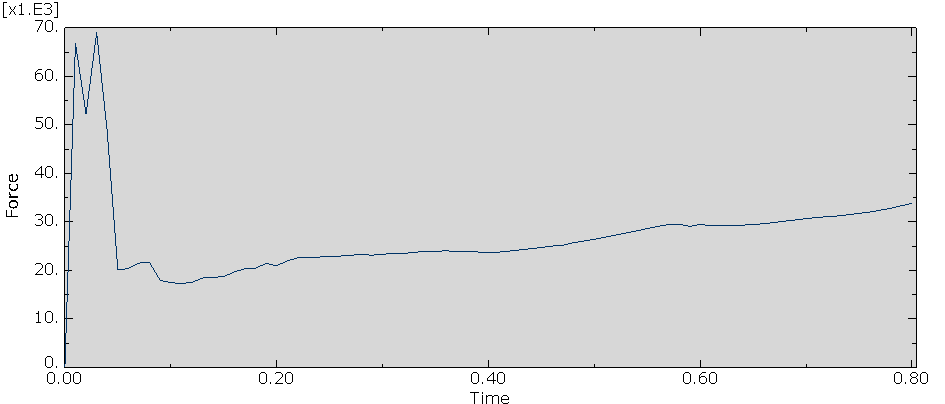
Figure 3
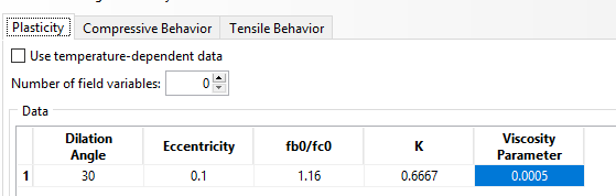
Figure 4
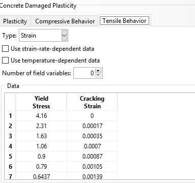
Figure 5
A: First of all, you cannot enter random material from a YouTube video and expect to get similar results to the experimental ones. The data you enter must match the ones in the experimental test.
Second, you need to check the data you use is True or engineering and must match the experimental data. If the stress data is True, the diagram you obtained might be correct.
The last thing I recommend is checking the input data units and rechecking your model; you might have done something wrong. I suggest referring to the link below as well. It might help you a lot.
Abaqus Tutorial for Beginners (Abaqus Tutorial for Civil Engineering)
3. Concrete damaged plasticity (CDP) model in Abaqus
Q: I created a CDP model with enlarged boundary elements for a shear wall. I performed a nonlinear static analysis with a 500 mm displacement. I couldn’t observe any difference in results when I increased the amount of longitudinal reinforcement in enlarged boundary elements (column). I mean that the longitudinal bar confinement effect is not visible.
How do I get the confinement effect of ties while modeling an RCC column in Abaqus?
A: I don’t know how you increased the column reinforcement. I suggest rechecking your model. Please note that increasing the number of the bars and decreasing their cross-section simultaneously could cause them to counteract each other’s effect; therefore, the stress won’t change. If that’s what you did, you should change one of them or if you want to change both, do it properly to see its effects in your model.