The Beginner’s Guide to UAMP Abaqus (VUAMP) Subroutine | Introduction to Abaqus User-Defined Amplitude
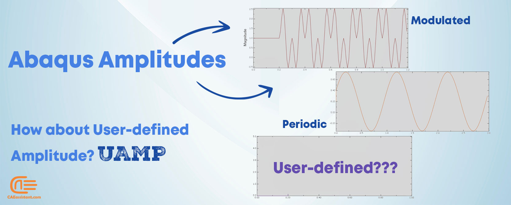
In the world of finite element analysis, accurately representing how loads change over time is crucial. This is where load amplitude definition comes in. Abaqus, offers various predefined amplitudes for common loading scenarios. But what if you need to simulate a more complex load pattern? Here’s where UAMP Abaqus (VUAMP Abaqus) and Abaqus user-defined amplitudes enter the scene. UAMP, specifically for Abaqus/Standard simulations, is a powerful tool that allows you to define custom load variations using subroutines. These subroutines can even incorporate data from Load Sensor Abaqus UAMP, enabling you to create highly realistic and dynamic loading conditions for your Abaqus simulations.
In this article, we will dive into the world of UAMP and VUAMP subroutines in Abaqus, exploring their functionalities, implementation, and potential applications. By the end, readers will have a better understanding of these powerful tools and how they can use these tools to enhance the accuracy and efficiency of their simulations.
1. Load Amplitude Definition: Understanding the Role of Load Amplitude in Engineering Analysis
In Abaqus, every load or boundary condition you define in your model needs to have an amplitude. Amplitude determines the time variation of the load during the loading step (Load Amplitude definition). When simulating the behavior of a structure under various loading conditions, understanding the concept of load amplitude is crucial. In Abaqus, load amplitude plays a vital role in accurately predicting the response of a structure to external forces.
Load amplitude refers to the magnitude of the load the user can apply to the structure during the simulation. It is an important parameter that directly influences the level of stress, strain, and deformation experienced by the structure.
Load amplitude is a key parameter in Abaqus simulations. By defining and adjusting load amplitudes, engineers can gain valuable insights into structural behavior. And this will ultimately lead to improved design and performance. Understanding load amplitude in Abaqus is essential for conducting comprehensive and reliable finite element analyses.
1.1. Different available amplitudes in Abaqus
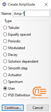
In Abaqus, load amplitudes are defined in various ways, depending on the type of analysis. You can choose from the following list shown in figure 1 to define an amplitude in Abaqus.
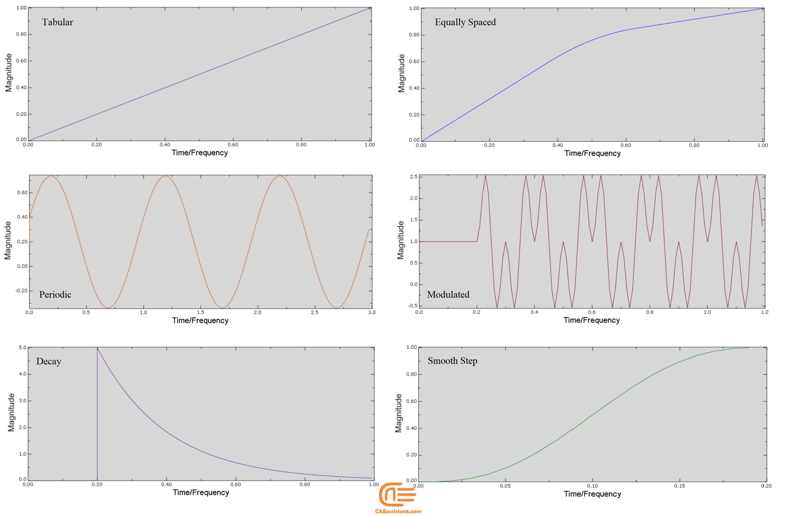
For each amplitude, you need to enter the related parameter values requested and Abaqus will create the amplitude curve based on the entered values. For “User” amplitude you must provide a UAMP or VUAMP subroutine. You can see some of the most common amplitude curves of the above list in Figure 2.
Figure 1: List of available amplitudes in Abaqus
Figure 2: Some of the most common amplitude curves in Abaqus
Now, let’s define and make examples of common Abaqus Amplitudes to better understand them.
Abaqus provides several predefined amplitude types to control how loads and boundary conditions change over time. These amplitude definitions can be applied to different kinds of analyses, such as static, dynamic, and thermal.
1.1.1. Tabular Amplitude
- Description: This allows you to define custom time-amplitude pairs. You specify a list of time points and the corresponding amplitude values. Abaqus then interpolates between these points to create a continuous curve.
- Example: Imagine you want to simulate varying wind pressure on a building over time. You can input the wind speed at various times, and Abaqus will interpolate the changes smoothly.
Figure 3 shows a table of points and the corresponding curve. As you can see in the picture, when the smoothing option is set on thw Use solver default, automatically the corners of the graph is rounded. If you want to determine the curvature yourself, you must use the “Specify” option.
Figure 3: Tabular Amplitude curve
1.1.2. Equally Spaced Amplitude
- Description: Similar to the tabular amplitude, but instead of specifying both time and amplitude values, you only specify the amplitude values, and Abaqus assumes equal time intervals between them. It simplifies data entry for evenly spaced time increments.
- Example: Suppose a structure experiences uniform force increments at regular intervals (e.g., every 10 seconds). You only need to input the amplitude values, and Abaqus handles the timing.
Figure 4: Equally Spaced curve
1.1.3. Periodic Amplitude
- Description: This amplitude is used for repeating loads or cyclic behaviors, such as vibrations or oscillations. It uses a Fourier series to define a function that repeats at regular intervals.
- Example: You can model the vibration of a bridge under repetitive traffic loads, simulating the cyclic nature of the load as vehicles pass over it continuously.
In the Edit Ampitude dialog , the cicular frequency is equal to the range that the graph will repeat. The starting time and the initial Ampitude are respectively time and magnitude that drawing the curve will start from there. A value is equal to the initial value of magnitude that is added to the beginning of the curve . And B is the Amplitude of the curve.
Figure 5: Periodic Amplitude curve
1.1.4. Modulated Amplitude
- Description: Combines two sine functions to create a modulated waveform. It’s useful when you need to simulate a load that has a periodic nature but also changes in intensity over time.
- Example: Simulating a wind turbine experiencing both regular wind patterns and intermittent gusts.
Like priodic amplitude, initial amplitude and starting time are show the starting magnitude and time. also Amplitude parameter determine the range for curve.
Circular Frequency 1is the first sine wave’s frequency, which determines the primary oscillation rate, and Circular Frequency 2 is The second sine wave frequency used to modulate the first, altering the oscillation pattern.
Figure 6: Modulated Amplitude
1.1.5. Decay Amplitude
- Description: This amplitude type models loads that decrease exponentially over time, ideal for simulating situations where a force or effect gradually is reduced after an initial impact.
- Example: Imagine dropping an object into water. The impact force would be strong at first but would quickly reduce as the object settles.
For this amplitude you sould define Initial Amplitude that is the starting magnitude of the load or boundary condition before decay begins, Max Amplitude is the maximum value the amplitude reaches before starting to decay, Starting Time is the point in the simulation time when the decay begins, and Decay Time is the time over which the amplitude decreases from the maximum value to the final value.
Figure 7: Decay Amplitude
1.1.6. Smooth-Step Amplitude
- Description: It uses a fifth-order polynomial to create smooth transitions between load levels. This avoids sudden jumps, making it ideal for gradually increasing or decreasing loads without sharp transitions.
- Example: When applying a load to a delicate structure, you would want to ramp up the load smoothly to prevent shock, and then reduce it similarly.
Figure 8: Smooth-Step Amplitude
1.1.7. Solution-Dependent Amplitude
- Description: This advanced amplitude type adjusts based on the simulation results, making the load dependent on factors like strain or stress within the model.
- Example: In a superplastic forming process, where material properties change during deformation, the applied pressure can automatically adjust based on the material’s strain rate, optimizing the forming process in real-time.
1.1.8. Actuator Amplitude
- Description: Used to simulate the behavior of actuators, typically mechanical systems like hydraulic or pneumatic cylinders. The amplitude controls the movement or force of the actuator over time.
- Example: Simulating a hydraulic press applying a force on a material, where the force varies according to the actuator’s control system.
1.1.9. Spectrum Amplitude
- Description: Defines a frequency spectrum used in dynamic analyses, such as seismic loading, where the input load varies with frequency.
- Example: Applying seismic forces to a building structure using a response spectrum to simulate an earthquake.
| Speaking of seismic loading, did you know concrete gravity dam design requires specialized analysis to handle earthquake forces? Our tutorial package guides you through seismic analysis with Abaqus subroutines, ensuring your dam designs are up to the challenge. |
1.1.10. PSD (Power Spectral Density) Amplitude
- Description: This is used for random vibration analysis, representing how power is distributed over various frequencies. It’s essential for simulating random environmental vibrations.
- Example: Modeling the vibration of a vehicle subjected to road-induced vibrations over a range of frequencies.
1.1.11. User Amplitude
- Description: This allows users to define a custom amplitude through a user subroutine, providing the flexibility to simulate complex or highly specialized loading conditions.
- Example: Defining a custom vibration pattern for a machine component that requires specific operational behavior beyond predefined Abaqus amplitudes.
So, these were the common Abaqus amplitude curves, right? how about an user-defined curve, such as a time dependent amplitude? You must select the “User” option (see figure 1) and then use the UAMP Abaqus subroutine. You ask how to do that? See examples in this link: “UAMP subroutine (VUAMP subroutine) in ABAQUS“
2. Custom Amplitudes: UAMP Abaqus (VUAMP Abaqus)
One of the available amplitudes you can use in Abaqus is the “User” amplitude. In case of using the user amplitude, you must provide a UAMP Abaqus (for Abaqus Standard) or VUAMP Abaqus (for Abaqus Explicit) subroutine for the model.
While Abaqus provides a robust library of predefined amplitudes, real-world scenarios often demand more intricate load patterns. Enter UAMP Abaqus, a game-changing tool that empowers users to define custom time-dependent loads through user-written subroutines. This functionality extends to Abaqus/Standard simulations, allowing for the creation of highly specific loading behaviors that precisely mimic real-world conditions.
Continue reading this article to get more specific info about the UAMP subroutine. But here is the thing; if you need some examples I suggest to check out this: “UAMP subroutine (VUAMP subroutine) in ABAQUS“
3. When do you need to use Abaqus user-defined amplitude?
The answer is, when your amplitude:
- is not available in pre-defined Abaqus amplitudes.
- is dependent on the analysis state variables or properties.
- uses solution-dependent sensors.
By choosing user amplitude (Abaqus user-defined amplitude), you are free to define any time-dependent amplitude you have in your mind. In this case, you can write your subroutine using mathematical time-dependent functions or using sensors you have defined in your model.
Now we provide you some examples of using these two subroutines.
Consider a case in which you need to control the temperature of a sample in an induction furnace. So, you have an electrical-thermal analysis and you need to control the current input in order to control the sample temperature. You can control the sample heating rate through the user-defined feedback control subroutine, UAMP [1].
In a research, in order to analyze the global spatial dynamic response of a submerged floating tunnel the UAMP subroutine is used to simulate the effect of hydraulic resistance. The velocities in this case recorded by sensors and then transferred to the UAMP subroutine to calculate the corresponding hydraulic resistance load amplitudes. You see a schematic of this process in figure 9 [2].
Figure 9: Schematic diagram of the hydraulic resistance acting on the submerged floating tunnel (SFT) tube; vertical velocity (Vvi) and horizontal velocity (Vhi) at the center point of each segment, hydraulic resistance load amplitudes (AMPvi and AMPhi)[2]
Sometimes you need a signal in order to stop the analysis at a specific time. In UAMP Abaqus, you can set flags that cause Abaqus to terminate the current step, which is defined as a distinct loading event (such as load cycling, or cracking and re-equilibration of stresses after crack extension) [3].
4. Load Sensor UAMP Abaqus: Understanding and Implementation
Sensors are features to sense and record the values of a parameter at the defined location. In Abaqus, you can define sensors to record values at each increment at the special place you defined in your model and then you can use this recorded data in your subroutine such as UAMP Abaqus or VUAMP Abaqus. To define a sensor, you must follow the following instructions:
- You must uniquely associate a sensor with a particular scalar output variable (U1, CTF3, etc.)
- You must specify the sensor name in the history output definition, and you can define one and only one nodal output, element output, or whole surface request for each sensor. For whole surface contact or contact pair output requests, only the magnitude and the center of the total force due to contact pressure (CFNM and XN, respectively) are acceptable.
- Because the named sensor must be a unique real number at a given time, the node set or element set used to define the sensor must contain only one member.
- Regardless of the user-specified output frequency, sensors are computed at every increment during the analysis. However, they are written to the output database according to the user-specified frequency.
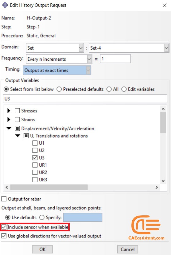
To define a sensor in Abaqus/CAE, after creating a history output while considering the above instructions, you must click the checkbox “Include sensor when available” as shown in figure 10.
Figure 10: Sensor definition in Abaqus
Now, do you like to these examples by yourself? First step is to start with simple ones and understand how does this subroutine work. How? check this out:
5. UAMP and VUAMP Abaqus subroutines structures
After choosing “User” amplitude in Abaqus, you require a UAMP Abaqus or VUAMP Abaqus subroutine to define amplitude. If you use Abaqus/Standard, you need to write a UAMP subroutine and if you use Abaqus/Explicit you must write a VUAMP.
You can define your amplitude in these two subroutines as an analytical function or you may use sensor values you have defined in your model.
Both of these subroutines consist of three main sections:
- In the first section of the UAMP/VUAMP Subroutine, the variables are introduced. Variables are used to define amplitude and can be divided into three groups:
1) “Variables to be defined” are those used to store values or intermediate results obtained at some point in program processing for additional processing or display
2) “Variables that can be updated” are those that can be updated at the end of each time increment to be used in further increments by updated values.
3) “Variables passed in for information” are those you must not redefine these variables in your subroutine.
- The second section of the subroutine is for defining parameters and flags. Flags are indicators to check or determine a parameter calculation status. For example, if the flag value of a parameter is equal to one, then you must provide the parameter calculation formula in your subroutine; otherwise, the value of the parameter computes automatically.
- The third section contains defining arrays’ dimensions and characters. You must write the user amplitude formulation as a subroutine in this section.
5.1. Differences between VUAMP and UAMP Abaqus subroutines
The main difference between these two subroutines is the solvers you use for each in Abaqus. In the case of Abaqus/Standard, you must use the UAMP Subroutine. In the case of Abaqus/Explicit you must use VUAMP Subroutine.
The variables almost have the same definition but may be different in the case of some “Variables that can be updated” and “Passed in for information Variables”.
6. Summary
Amplitude functions are critical for accurately representing time-varying loads and boundary conditions within Abaqus simulations. They are essential for capturing transient, dynamic, and user-defined loading scenarios in finite element analyses. One available amplitude in Abaqus is “User” which needs you to provide a subroutine for it. Two subroutines in Abaqus documentation introduced for this purpose are “UAMP” and “VUAMP”. (UAMP Abaqus) (VUAMP Abaqus)
The user subroutine amplitudes “UAMP” and “VUAMP” serve as a powerful tool for customizing time-dependent loading conditions within the Abaqus simulation environment, enabling engineers to accurately capture the real-world behavior of structures and components in their simulations.
Both UAMP and VUAMP subroutines provide advanced simulation capabilities within the Abaqus. And the user is capable of defining any amplitude that exists in a real situation doesn’t matter how complex it may be.
7. Users ask these questions
Now, let’s see some questions users ask regarding the amplitude and changing the amplitude magnitude in their favorite. We tried to help them and answered them as best we could at the time.
I. Is it possible to update nodal force in each increment by the user?
Q: I am doing a dynamic analysis in Abaqus Standard (Dynamic implicit method), in which, for each increment, we have to give nodal force from outside (or from a text file).
We can give a non-uniform distributed load using the DLOAD subroutine, but it applies to integration points, not nodes.
Another option is updating the input file with new nodal forces in each increment and running the jobs; then, the analysis becomes quasi-static.
A: You can add nodal force with concentrated force and change it during time via amplitude.
– But in that case, we don’t have a provision to control or update nodal force in each increment.
– By adding amplitude you can define the nodal force vs increment or as a function. If you do not know how the nodal force is changing during the time in the first of analysis and the nodal force has been defined based on the result during the time you need UAMP subroutine or scripting.
– You have mentioned the DLOAD subroutine. You should use the UAMP subroutine to control amplitude during the time using the sensor.
This package “UAMP subroutine (VUAMP subroutine) in ABAQUS” introduces UAMP and VUAMP subroutines in Abaqus (UAMP Abaqus). The UAMP and VUAMP refer to User-Defined amplitude. In Abaqus, load amplitude refers to the time-varying function that defines the magnitude and pattern of a load applied to a model during analysis. This amplitude can be defined using predefined amplitude functions or by creating a user-defined amplitude using the UAMP or VUAMP subroutines. The load amplitude can be applied to various types of loads including force, pressure, displacement, and temperature, allowing for a wide range of loading scenarios to be simulated in the analysis. The load amplitude plays a critical role in determining the response of the model over time. The UAMP and VUAMP (UAMP Abaqus, VUAMP Abaqus) subroutines can be determined by a mathematical time-dependent function or using sensor values that are defined by the user in analysis. In Abaqus, sensors are used to monitor and extract data from a simulation during its execution. In this package, you will learn all about the UAMP and VUAMP subroutines, all of their variables, how to work with them, their differences, and other things along with educational workshops to help you understand working with these subroutines.
It would be helpful to see Abaqus Documentation to understand how it would be hard to start an Abaqus simulation without any Abaqus tutorial.
One note, when you are simulating in Abaqus, be careful with the units of values you insert in Abaqus. Yes! Abaqus don’t have units but the values you enter must have consistent units. You can learn more about the system of units in Abaqus.

