Extended Finite Element Method in Abaqus | XFEM Tutorial tutorial
In complex engineering fields, the Extended Finite Element Method (XFEM) has become a powerful tool for simulating issues like crack formation and propagation in materials without needing detailed mesh alignment. Unlike the traditional Finite Element Method (FEM), XFEM allows for modeling discontinuities within a material, such as cracks, by enriching standard finite element methods with unique functions. This advantage makes XFEM especially useful for studying complex material failures across multiple scales.
Damage analysis in XFEM relies on methods that capture discontinuities and stress distributions around cracks efficiently. This includes enrichment functions that accurately represent crack surfaces and cohesive laws that model the behavior of materials under stress. When combined with the partition of unity method, XFEM becomes a robust solution for capturing the complex behaviors in multi-phase materials. For engineers and researchers, simulation in software like Abaqus offers precise control over these methods, enabling in-depth analysis of cracks, material interfaces, and multiple crack interactions within a single model.
This blog explores the core concepts and applications of XFEM in detail, focusing on enrichment functions, interface modeling, and cohesive crack simulations. You’ll learn about the difference between FEM and XFEM, the mechanics behind enrichment functions, and the process of modeling complex materials with multiple cracks in Abaqus. Step-by-step examples are provided for both 2D and 3D crack growth simulations in Abaqus, offering valuable insights into setting up accurate XFEM Abaqus simulations for various engineering challenges.
The tutorial packages below are the list of packages that implement XFEM Abaqus method in fields such as fracture and crack growth analysis.
1. FEM vs. X-FEM: Choosing the Right Approach for Multi-Scale Crack Failure Models
For multi-scale failure models, particularly those involving complex material behaviors, the Extended Finite Element Method (XFEM) is often preferred over the traditional Finite Element Method (FEM). XFEM’s ability to model discontinuities like cracks or voids without requiring mesh refinement at each failure site makes it highly suited to multi-scale problems where fine-scale details interact with larger structural behaviors. In multi-scale failure, phenomena such as crack initiation and propagation, plasticity, and localized damage require modeling at different scales, from microscopic material flaws to macroscopic structural failure.
Therefore, examining and simulating X-FEM is one of the requirements for simulating such issues. In this article, we are trying to introduce a small corner of the theory and how to use this critical model in Abaqus (Abaqus XFEM).
2. What is XFEM?
Let’s start by defining X-FEM. X-FEM stands for Extended Finite Element Method. The “extended” part refers to its enhancement of the traditional finite element method, particularly for simulating crack propagation.
So, why extend the traditional method? Cracks cause discontinuities in the functions used to approximate things like displacement, temperature, and flux in finite element analysis. This makes an enhanced approach necessary. X-FEM is especially useful for modeling cracks and dislocations, as it integrates near-field solutions using the Partition of Unity (PU) method, improving accuracy even with coarse meshes.
X-FEM is valuable for studying phenomena like nano-mechanics, void growth, and interface behavior at smaller scales. It has greatly improved FEM’s ability to solve materials-related problems.
Some key applications of X-FEM include:
- Linear Elastic Fracture Mechanics (LEFM)
- Cohesive Fracture Mechanics (Abaqus Cohesive Behavior)
- Composite Materials and Inhomogeneities
- Plasticity (Abaqus Plasticity), Damage, and Fatigue analysis
- Shear Band Localization
- Fluid-Structure Interaction
- Fluid Flow in Fractured Porous Media
- General Fluid Mechanics
- Phase Transition and Solidification
- Thermal and Thermo-Mechanical Issues
- Plates and Shells
- Contact Problems
- Topology Optimization
- Piezoelectric and Magneto-Electroelastic Problems
- Multi-Scale Modeling
X-FEM has opened new possibilities, making FEM more effective for a wide range of engineering challenges.
| Explore our comprehensive Abaqus tutorial page, featuring free PDF guides and detailed videos for all skill levels. Discover both free and premium packages, along with essential information to master Abaqus efficiently. Start your journey with our Abaqus tutorial now! |
3. What is the difference between FEM and XFEM?
The Finite Element Method (FEM) is a powerful tool used to find approximate solutions to partial differential equations, making it indispensable in many engineering disciplines. From aerospace to civil engineering, biomechanics, and material sciences, FEM helps model and predict the behavior of structures and systems.
Instead of directly solving differential equations, FEM transforms them into variational forms, breaking down complex problems into smaller, manageable pieces called elements. These elements are connected in a mesh, with local polynomial approximations representing each one.
A major strength of FEM is its ability to handle complex boundaries, but it does have some limitations. For example, it works best when the solutions are smooth, but when dealing with sharp gradients, singularities (like in stress fields), or discontinuities (such as cracks), the method can become computationally challenging and less accurate.
When cracks are present, FEM often requires refining the mesh near crack tips, which increases the number of degrees of freedom and can be demanding in 3D models. Additionally, simulating incremental crack growth involves frequent remeshing, which can be costly and affect the accuracy of results.
Despite these challenges, FEM remains a cornerstone in engineering, offering unparalleled versatility and precision in solving complex problems. quality. The classical FEM has therefore reached its limits in addressing fracture mechanics problems.
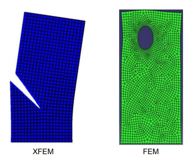
Figure 1: difference between FEM and X-FEM [Ref]
A New method take to overcome the challenges that FEM has created, has been stated. The extended finite element method (X-FEM), created by Dolbow in 1999, uses a partition of unity to boost the finite element approximation with special functions. This setup lets us model cracks with functions that aren’t continuous, like the Heaviside step function, without needing to mesh the crack itself explicitly (check out Fig. 1).
4. Theory of XFEM
The extended finite element method (XFEM) is a novel numerical technique introduced in the early 2000s for modeling joints and cracks in a domain without the need to conform to the mesh.
The method is based on the concept of partition of unity, which enables standard finite element approximations to be “enriched” with additional functions that capture discontinuous or singular behavior within elements. This enhancement is particularly useful for problems where the crack path is not predefined or does not align with mesh boundaries, such as in simulations of arbitrary crack propagation and interaction.
Figure 2: An example of releasing a crack on X-FEM
In this section, we’re excited to introduce you to the theory of the extended finite element method (X-FEM)! We’ll start by exploring the idea of enrichment functions, which will help us understand material interfaces. After that, we’ll dive into crack propagation in the X-FEM model over two sections. We’ll wrap things up with a brief look at numerical X-FEM. Then, in the following section, we’ll see how to apply XFEM Abaqus with two practical examples. Let’s jump in!
4.1. Enrichment Functions
Enrichment functions are like giving FEM a turbo boost, letting it tackle complex problems without requiring a mesh overhaul. Let’s explore what they are, why they matter, and how they work in a way that’s easy to understand!
Enrichment functions are handy mathematical tools that we add to the Finite Element Method (FEM) framework to help us deal with features like cracks or different materials. You can think of them as special lenses that help us see important details that standard FEM might miss. With these enrichment functions, the Extended Finite Element Method (XFEM) can tackle things like breaks and sharp changes in materials more effectively.
Here’s the main idea:
When a crack forms in a material, it causes a jump in displacement, which means there’s a discontinuity. Plus, right at the tip of the crack, the stresses can become extremely high a situation known as a singularity. While standard FEM can find it tough to manage these scenarios, enrichment functions allow XFEM to handle them smoothly and effectively. Now the question is how does it work. Let’s start like this:
In traditional FEM, the displacement u(x) at any point x is calculated by summing up the contributions of nearby nodes:
Here:
- Ni(x): Shape functions (determine how the displacement varies).
: Displacement at the
-th node.
XFEM adds extra terms to capture more complex behaviors:
In this context, represents the shape function for the
th node. The set
includes all the nodes within the domain, while
refers to the set of enriched nodes. The terms
and
denote the sets of standard and (DOFs). As we know, the enriched degrees of freedom are the new variables associated with the enrichment functions added to the standard FEM solution. These DOFs allow the model to account for the effects of discontinuities (such as a crack) at specific locations in the domain, even if the discontinuity doesn’t align with the finite element boundaries, respectively.
Φ(x): Special functions (like asymptotic crack-tip functions) model the singular stress field near a crack tip.
One of the most commonly used enrichment functions in XFEM is the Heaviside function, denoted as H(x). The Heaviside function is a mathematical tool that creates a jump in the displacement field across a discontinuity. In other words, it allows us to represent the sudden change in displacement that occurs at the crack or interface.
Think of the Heaviside function as a switch that turns on or off depending on whether the point in question is on one side of the crack or the other. On one side of the crack, the displacement field will be a value; on the other, it will be a different value. XFEM uses this “jump” in the displacement to accurately model the crack without changing the mesh.
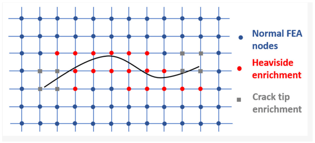
For example, as shown in the diagram below (Figure 3), the crack intersects the element. Thanks to the Heaviside enrichment, XFEM can account for the displacement jump across the crack, even though the crack doesn’t align with the mesh lines.
Figure 3: Heaviside enrichment of nodes [Ref]
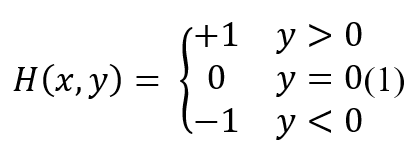
To accurately represent the discontinuity in the component, the Heaviside function is employed. This function differentiates each side of the crack (or joint) and is defined as:
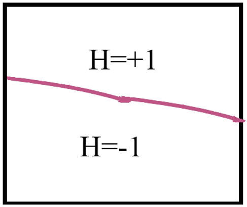
Figure 4: Heaviside function cutting through an element
The coordinates (x, y) represent the position of any point within the domain, using the local coordinate system relative to the crack. Imagine a crack cutting through an element (see Figure 4). The Heaviside function is used to model the discontinuity created by the crack. It assigns a value of +1 on one side of the crack and −1 on the other, allowing XFEM to identify the discontinuity’s location precisely. This information then modifies the displacement field, ensuring the crack is accurately represented.
This methodology can be easily extended to handle multiple cracks (or joints) within the domain. Each element in the mesh has four nodes, and whenever a node of an element intersects with a crack, we use enrichment functions to improve the accuracy of the solution at that node. However, if two cracks (or joints) intersect, additional considerations are required to ensure the interaction between the cracks is modeled correctly.
There are three main scenarios in which pairs of cracks may intersect, and the following figure illustrates these interactions.
Figure 5: Three cases of functions for (a) Fully crossed (b) semi-crossed (c) end crossed [Ref]
When two cracks completely intersect each other, as shown in Figure 5-a, we can define the interaction between them using the product of the Heaviside functions for each crack. This is represented as 𝐽(𝑥) = 𝐻₁(𝑥) * 𝐻₂(𝑥), where 𝐻₁ and 𝐻₂ are the Heaviside functions for the individual cracks. This joint function creates four distinct regions within the element where the cracks intersect. In this scenario, all nodes within the element maintain their individual Heaviside enrichments for both cracks. Additionally, the function (Φ (𝑥)) provides an extra enrichment to these nodes to account for the intersection.
If one of the cracks is considered the primary crack, the other crack is referred to as the secondary crack. In this case, the Heaviside enrichment for the major joint is retained, while the enrichment for the primary crack is removed.
In the third scenario, if both cracks are treated equally, both Heaviside enrichments are discarded, and only the function (Φ (𝑥)) enrichment is kept to represent the interaction between the two cracks.
By adding H(x) and Φ(x) into the displacement field, XFEM becomes capable of modeling cracks and singularities without remeshing. It’s like upgrading your standard tools to specialized ones that can handle unique challenges.
The total displacement approximation looks like this:
u(x)=(Standard FEM part)+(Heaviside enrichment for cracks)+(Crack tip enrichment for singularities)
These characteristics are best showcased at material interfaces, the boundaries where two different materials meet.
4.2. Material Interfaces
Like composite materials, multi-phase materials consist of different phases that each contribute to the overall mechanical behavior. The interfaces where these phases meet are crucial, as they can be vulnerable to debonding or cracking when the material is subjected to stress. Traditional finite element methods (FEM) face challenges when modeling these interfaces because they often require complex mesh adjustments to capture the behavior accurately. The Extended Finite Element Method (X-FEM), combined with the level set method, offers a more efficient solution. X-FEM allows for the modeling of interfaces without needing to alter the mesh. By using the level set method, X-FEM represents these interfaces implicitly. Imagine a function ϕ(x) such that:
This definition partitions the domain into regions, making it easy to identify which material a point belongs to. The zero contour (ϕ=0) represents the actual interface. Let us explain this function better: The level set function defines the interface as the zero level set of a scalar function, making it possible to model complex, evolving shapes without modifying the underlying mesh. This approach is particularly useful in handling cracks or phase boundaries in materials without the computational complexity of mesh refinement.
These functions are designed to capture both weak and strong discontinuities at interfaces, such as cracks or debonding, without being dependent on the mesh structure. When debonding or cracking occurs along an interface, cohesive zone models (CZM) are used to describe the relationship between the tractions (forces) and displacement jumps across the interface (What is the CZM? We will discuss it later.). Specifically, a traction-separation law (The traction-separation law is a fundamental concept used to model the behavior of interfaces, such as cracks or material boundaries, under loading conditions), often exponential in form, is applied. This law governs the stress distribution as the crack opens or grows, ensuring that both the normal (perpendicular) and tangential (shear) components of the crack behavior are captured accurately. By doing so, the cohesive zone model provides a realistic representation of the material’s failure, including the initiation and growth of cracks.
4.3. Crack Cohesive Model
First, let’s say what the Crack cohesive model is. The method really shines when it comes to numerical simulations of cohesive crack growth in composites! It shows strong performance, even when we use different mesh configurations. We carefully handle the integration over the cohesive zone and the domain separately, which helps us accurately track how the crack behaves. This is super important for making sure the cohesive crack grows smoothly without us having to tweak the mesh or make any adjustments.
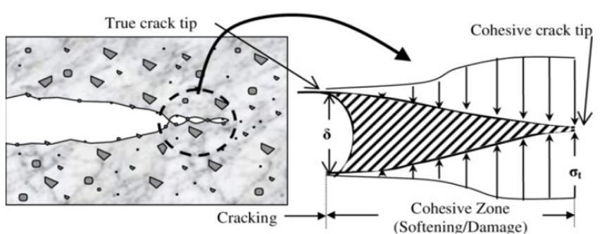
Figure 6: cohesive crack growth in composite [Ref]
Figure 6 shows how the Cohesive model works. As you can see, the cohesive zone is a small region near the crack tip where the material’s internal resistance (cohesion) exists before the crack completely propagates. The material doesn’t instantly fail or separate as soon as a crack initiates; rather, it undergoes a process of progressive degradation in the cohesive zone. In this zone, the material exhibits both stress (resisting the crack’s opening) and strain (related to the deformation of the material in the process of separation).
So a crack cohesive model is used to simulate crack initiation and propagation by modeling the material’s behavior within the cohesive zone the region ahead of the crack tip where the material still resists separation. The model is governed by a cohesive law, which defines the relationship between traction (stress) and separation (displacement) and includes failure criteria for crack propagation. This approach is essential in simulating material failure, particularly in composite materials, adhesives, and other heterogeneous materials.
Finally, integrating cohesive zone models into the extended finite element method (X-FEM) allows for exceptionally accurate simulations of crack growth and material failure. X-FEM enables cracks to propagate smoothly within the existing mesh, eliminating the need for remeshing. This capability facilitates dynamic crack evolution while ensuring computational efficiency and precision.
4.4. Multiple cracks and crack nucleation
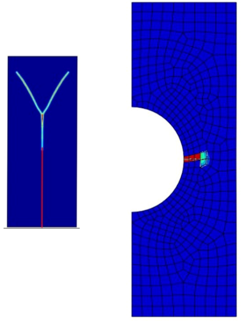
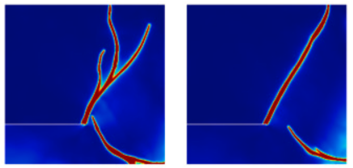
Addressing multiple cracks in materials is vital in fields such as civil and aerospace engineering, where materials frequently experience complex stress conditions(fig 7).
Figure 7: An example of crack branching
When it comes to voids—regions within a material where there’s no structure—X-FEM uses a unique function called the enrichment function, labeled V(x). This function acts like an “on-off” switch, letting us differentiate between areas with material and areas without.
Here’s how it works:
- Inside the Material: V(x)= 1 when we’re in the solid part of the structure.
- Inside the Void: V(x)=0 where there’s a void, effectively removing that part from the mesh.
By multiplying the shape functions of nodes near voids by V(x), we shrink their influence to only the material areas, making calculations more accurate and efficient. If a node is entirely within a void, its degrees of freedom are eliminated (or set to zero), cutting down on unnecessary computations.
Cracks that branch out into multiple paths or intersect with each other can be tricky to model(fig6), but X-FEM’s approach handles it with ease by using discontinuous enrichment functions. These functions add flexibility to the FEM mesh, allowing cracks to run through the material without disrupting the mesh itself.
Key components for handling branched cracks include:
- Discontinuous Functions: For each crack, we have a function, H(x), that defines a clear discontinuity across the crack. When cracks branch or intersect, we add more functions—like HI(x) and HII(x) to handle each segment separately.
- Junction Function J(x): At points where cracks meet, we use a special junction function. This function makes sure each branch of the crack behaves independently and accurately at the intersection, giving a realistic model of stress distribution in these complex areas.
4.5. Numerical Integration
In X-FEM, elements that intersect with a crack (or another discontinuity) require special attention to accurately capture the displacement field around the crack. However, since the crack geometry does not align with the mesh, standard integration over these elements can lead to inaccuracies, especially near the crack path. By subdividing these cut elements into smaller sub-elements, X-FEM achieves more precise integration of enrichment functions within each region, respecting the discontinuities across the crack surface.
Integrating X-FEM functions presents two main challenges: the discontinuity along the crack and the singularity at the crack tip. To address the numerical integration of cut elements, dividing them into standard sub-elements is common. High-order Gauss quadrature rules should be employed for accurate results within these sub-elements. The approach involves triangulating each side of a cut element to create a set of sub-triangles. However, some researchers have opted for a slightly different method to partition cut elements into sub-quadrilaterals instead. (fig 8)
Figure 8: How to Partitioning into standard sub-elements [Ref]
The numerical integration procedure for elements that are intersected by a crack is as follows:
- Construct the Delaunay triangulation to create the sub-elements:
This method in computational geometry creates a network of triangles (or tetrahedra in 3D) across a domain, ensuring stability and precision in numerical calculations. This technique is crucial for accurately modeling discontinuities, such as cracks, within a structure. The process begins by identifying “cut elements,” or elements that the crack intersects. These elements need to be subdivided into smaller parts to capture the geometry of the crack more precisely.
Delaunay triangulation divides these cut elements into smaller sub-elements, typically as triangles in 2D. This refined network of sub-elements follows the crack’s path closely, even within a single cut element, allowing for more accurate integration. Integration points are then strategically placed within each sub-element to perform Gaussian quadrature, essential for evaluating the stiffness matrix and force vector. This placement respects the crack’s exact position, ensuring that the enrichment functions in X-FEM correctly capture the discontinuity’s behavior.
- For each sub-element, compute the coordinates and weights of the Gauss points, and then convert these into the parent coordinate system of the original element:
When a finite element is intersected by a crack in X-FEM, it is subdivided into smaller sub-elements to capture the unique properties of each region. Gauss points are strategically placed within each sub-element using a Gaussian quadrature scheme, allowing precise integration over these irregular “cut elements” by aligning each Gauss point with the crack’s specific geometry. This localized integration method enables X-FEM to achieve high accuracy around crack regions without requiring a fine mesh or remeshing, thus handling complex crack propagation efficiently while keeping computational demands manageable.
 |
⭐⭐⭐ Free Abaqus Course | ⏰10 hours Video 👩🎓+1000 Students ♾️ Lifetime Access
✅ Module by Module Training ✅ Standard/Explicit Analyses Tutorial ✅ Subroutines (UMAT) Training … ✅ Python Scripting Lesson & Examples |
5. XFEM Abaqus | Abaqus XFEM Tutorial
Abaqus leverages enrichment functions within XFEM to accurately model the discontinuities introduced by cracks. These enrichment functions include the Heaviside function, which captures the displacement jump across the crack surface, and near-tip functions representing stress singularities at the crack tip. Together, these functions enhance the model’s ability to simulate stress fields and deformation around the crack, leading to highly accurate results even in complex geometries. Additionally, XFEM Abaqus supports cohesive behavior in XFEM (XFEM Abaqus) analyses, allowing users to model material separation and fracture processes with realistic crack initiation and propagation, which is particularly valuable for brittle or composite materials.
In the following, we will see how to do a Abaqus XFEM crack simulation step by step in both 2D and 3D cases (Abaqus XFEM tutorial).
5.1. 2D Static Edge Crack
A two-dimensional(2D) static edge crack analysis using the X-FEM is a widely utilized approach in fracture mechanics, especially for materials and components that are susceptible to edge-initiated cracks.
Let us explain it like this. In a static edge crack model, the crack is considered stationary to focus on analyzing the stress, strain, and displacement fields around an existing crack without adding the complexity of crack growth. This approach simplifies the problem, as the geometry and mesh remain fixed, eliminating the need to determine crack propagation direction, growth increments, or geometry updates. Engineers often use stationary crack models to assess structural integrity under static loads, identifying critical conditions under which a crack might start propagating. This allows for a better understanding of stress intensity factors (SIFs), crack tip stress distributions, and deformation, helping ensure safety without the computational overhead of dynamic modeling.
Additionally, stationary crack models align with fracture mechanics principles, where solutions for stress intensity factors and energy release rates are derived under the assumption of a non-growing crack. These solutions are vital benchmarks for validating numerical methods like Abaqus XFEM before extending them to dynamic scenarios. Crack propagation models are only necessary when the applied loading exceeds the material’s fracture toughness or under cyclic and fatigue conditions. For most initial analyses, stationary models effectively provide insight into whether a crack poses an immediate threat to the structure or if it will remain stable under the given conditions.
The crack is located along the edge of a structure and is often subjected to loading conditions that create stress concentrations at the crack tip. Now, let’s see how to do XFEM Abaqus crack simulation step by step.
Note: All the values entered in the Abaqus would be in the SI unit system (m, Pa, …).
- Geometry
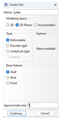
First, let’s see how to create the part and crack: open the Abaqus and navigate to the Part module. Click on “Create Part” tool, open it and name the part “Plate.” Set the Modeling Space to “2D Planar,” the Type to “Deformable,” and the Base Feature to “Shell,” with an Approximate Size of 5 (fig 9). Use the Rectangle Tool to draw a square from coordinates (-2, -2) to (2, 2), then click “Done.”
Figure 9: Create part
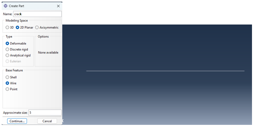
Next, you must create the crack geometry as well. Click on the “Create Part” tool again. Name the part “Crack,” set the Modeling Space to 2D Planar, Type to Deformable, Base Feature to Wire, and Approximate Size to 5. Draw a line for the crack from coordinates (-2, 0) to (-1, 0), then click Done (fig 10).
Figure 10: Create a cracked domain
- Material Properties
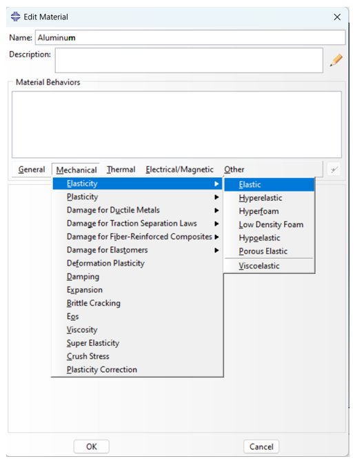
Next, According to Figure 11, the elastic properties of the material must be entered, set Young’s Modulus to 70 GPa and Poisson’s Ratio to 0.33.
Figure 11: apply material
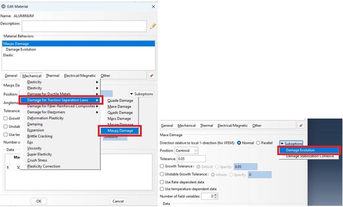
After that, the method of applying the damage must be specified. As mentioned, one of the models that models the cohesive behavior of the material well is “Damage for Traction Separation Laws”. The method of applying the damage is shown in Figure 12.
Figure 12: Apply damage properties
Go to Mechanical > Damage for Traction Separation Laws > Maxps Damage (fig.12) and input 500 MPa. In “Suboptions,” select “Damage Evolution” and set “Displacement at Failure” to 1. Click “OK” to confirm.
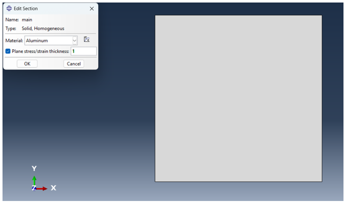
As can be seen in Figure 13, we need to create a section for the sample., and set the material to “Aluminum,” enabling “Plane Stress/Strain Thickness” with a thickness of 1.
Figure 13: apply section
Then, assign the section to the Plate by clicking on the “Assign Section” tool, selecting the domain, and clicking “Done”.
- Assembly
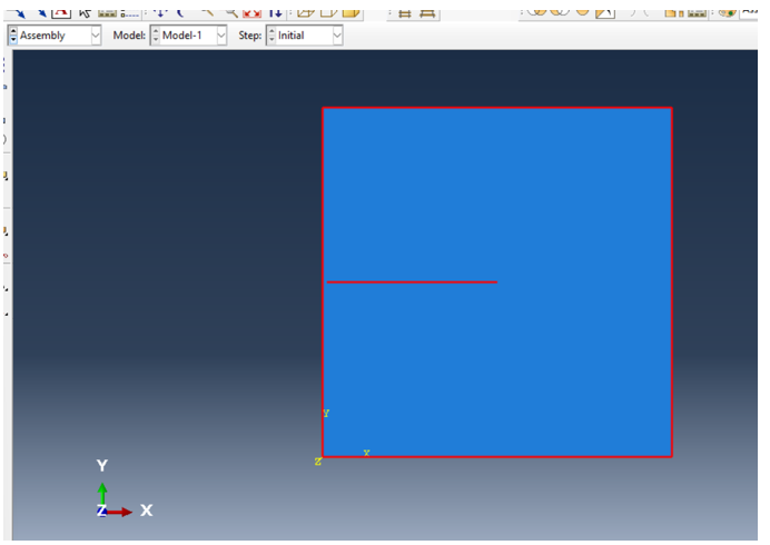
Next, we must assemble the plate and the crack to place the crack where we want according to the figure 14. Because we created both parts with the coordinates that place them exactly where we want, there is no need for adjustments; so, we just go to the Assembly module, create the instances of both parts and accept the default settings.
Figure 14: Assembly section
- Step
Now, we must create a Step for the analysis. Go to the Step module and create a “Static, General” step and accept the default settings. Next, click on the “Field Output Manager” tool, click “Edit” button, expand the “Failure/Fracture” output variables, and tick the variables in figure 15.
Figure 15: setting output variables
- Interaction
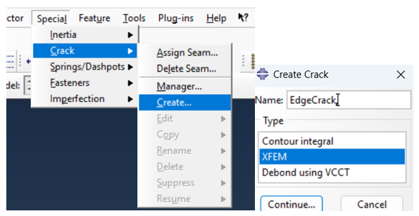
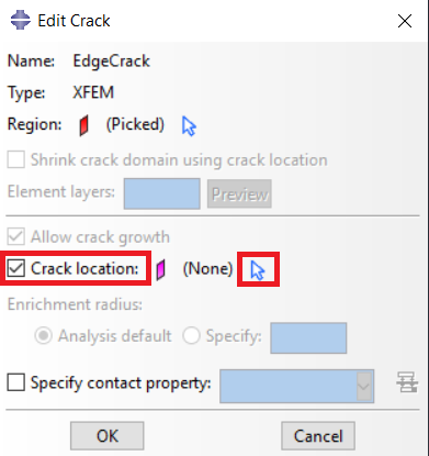
Now, we must define the Crack. To do so we must go to the Interaction module, open the “Special” menu from the top and according to the figure 16, define the XFEM crack. Go to Special > Crack > Create, name it “EdgeCrack,” and set Type to XFEM (fig 16). Click “Continue” and now you have to select the crack domain which in this case you should select the whole model; next, tick the “Crack location” option, click on the mouse cursor icon (fig 17) and select the line (crack), click “Done”, and now you have successfully defined the XFEM Abaqus crack.
Figure 16: How to allocate cracks in the software
Figure 17: Define crack location
The final thing in this section is to define the interaction between the crack and the plate. Click on the “Create Interaction” tool, select the Initial Step, Choose the “XFEM crack growth” type, ensure XFEM Crack is set to “EdgeCrack,” and finish by clicking OK.
- Boundary Conditions and Loading
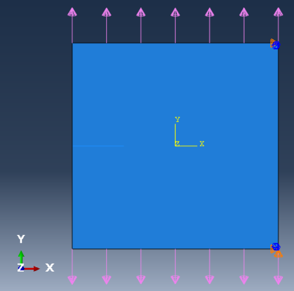
Go to the Load module. First, set the boundary conditions according to the figure 18; the right bottom point should be fixed (U1 = U2 = UR3 = 0), and the tight top corner must be U1 = UR3 = 0. Then apply the pressure load on both top and bottom edges and the magnitude is 100000 which means 100 KPa.
Figure 18: Boundary conditions and loading
- Mesh
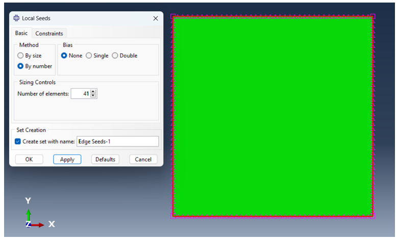
To mesh the plate, expand “Plate” and select “Mesh.” Choose “Seed > Edge by Number,” enter 41 for elements along each edge, then click “Done” (fig19).
Figure 19: apply mesh seed
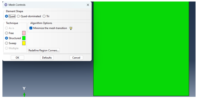
Figure 20 shows the meshing controls method.
Figure 20: mesh controls
- Job and Results
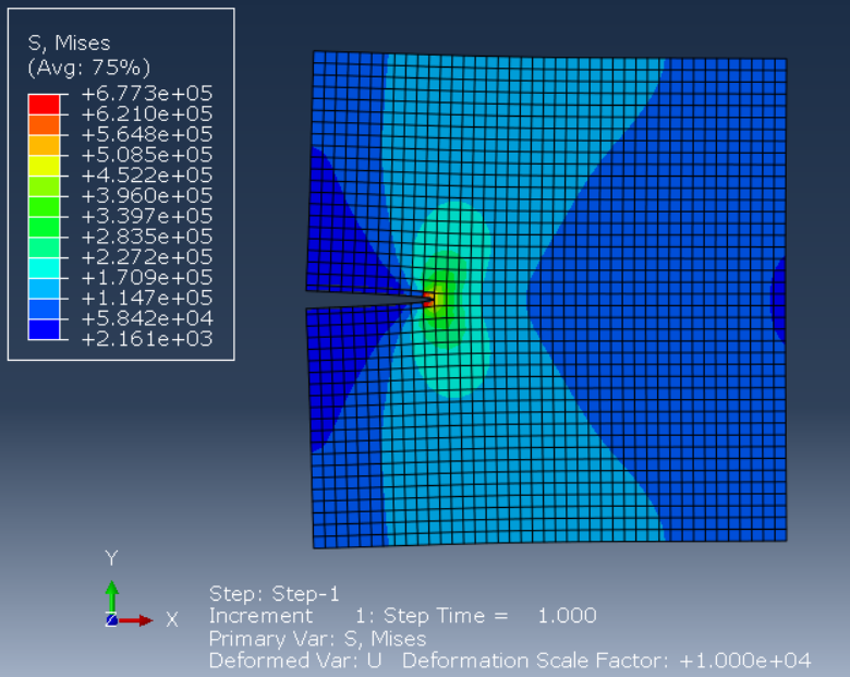
After creating a job and run the simulation, it’s time to see the results. See the Von Mises stress contour plot and to see the crack separation, increase the deformation scale factor (fig 21).
Figure 21: XFEM crack results
You can level up your skills in XFEM Abaqus through the examples below:
Abaqus XFEM simulation of three-dimensional crack growth in the concrete slab
Simulation of crack growth of a pressure vessel using Abaqus XFEM
5.2. 3D Static Edge Crack
To define the 3D geometry and crack location, create a solid model, such as a rectangular block or plate. This crack is modeled as a stationary edge feature, oriented either parallel or perpendicular to the applied load, to simulate crack behavior under structural loading conditions realistically. Pay attention to the following example, which is to simulate crack growth in 3D mode in Abaqus using X-FEM (XFEM Abaqus).
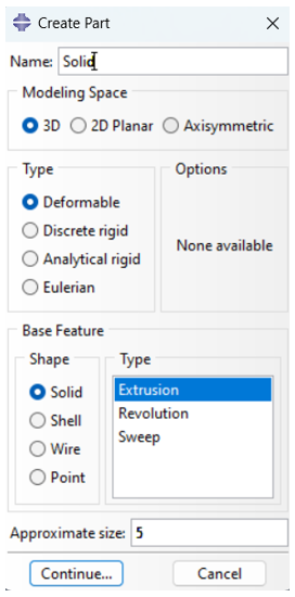
To start the analysis, open Abaqus/CAE and create the main part. Begin by navigating to Parts and double-clicking to open the dialog. Name the part Solid, set Modeling Space to 3D, Type to Deformable, Base Feature to Solid, and set an Approximate Size of 5 (fig 22). Click Continue. Using the Rectangle Tool, draw a square from coordinates (-2, -2) to (2, 2) and click Done. Enter a depth of 4 to complete the 3D solid and click OK.
Figure 22: Create main part
Next, define the material by double-clicking on Materials and naming it Aluminum. Under Mechanical, go to Elasticity > Elastic and set Young’s Modulus to 70 GPa with a Poisson’s Ratio of 0.33. For damage criteria, navigate to Damage for Traction Separation Laws > Maxps Damage and set the damage initiation value to 500 MPa. Under Suboptions, select Damage Evolution and input Displacement at Failure as 1 (fig 12). Click OK. Then, in Sections, create a section named Main using Aluminum as the material, with a thickness of 1, and apply it to the Solid part. Set up the mesh by selecting Seed > Edge by Number and setting 21 elements along each edge, followed by Mesh Controls set to Hex, Structured. Complete the mesh setup by selecting Mesh > Part and clicking Yes.
To define the cracked domain(crack part), return to Parts and create a new part named Crack. Set Modeling Space to 3D Planar, Type to Deformable, Base Feature to Shell, and choose Extrusion with an Approximate Size of 5. Draw a line from (-2, 0) to (-1, 0) and set the depth to 4. Add the Crack instance in Assembly by selecting Crack and clicking OK. To enable the crack, go to Interactions > Special > Crack > Create and name it EdgeCrack with the Type set to XFEM as like fig 16.
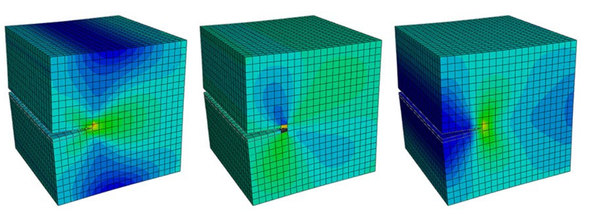
Finally, the boundary conditions are applied as in the 2D case, and after meshing and solving in the Job module, as shown in Figure 23, the stress concentrations are visible in the crack tip area, and the model is simulated.
Figure 23: 3D XFEM Abaqus crack model
Also, there are some examples below for 3D Abaqus XFEM:
6. Conclusion
Handling materials that experience fractures, cracks, or discontinuities in advanced engineering simulations poses considerable challenges. Traditional finite element methods (FEM) often struggle with modeling complex fractures due to the need for intricate mesh adjustments. This limitation has led to the development of an improved approach to address these challenges: the Extended Finite Element Method (XFEM).
The Extended Finite Element Method (XFEM) builds upon the traditional Finite Element Method (FEM) by incorporating specialized enrichment functions. These functions enable a more adaptable representation of cracks and discontinuities in materials. As a result, XFEM can model cracks without requiring the mesh to align perfectly with the crack’s path, which saves time and improves accuracy. In the Abaqus software, XFEM utilizes this capability, making it an effective tool for users working on damage analysis, multi-phase materials, and complex failure models.
In this blog, we explored the core concepts and applications of Abaqus XFEM. We compared FEM and XFEM to highlight how XFEM provides enhanced capabilities for crack propagation. The article delves into the theory behind XFEM, including enrichment functions, cohesive crack simulations, and material interfaces. Practical applications will include detailed guides on modeling both 2D and 3D crack growth scenarios, demonstrating the robust simulation capabilities Abaqus XFEM offers for engineering challenges.
The CAE Assistant is committed to addressing all your CAE needs, and your feedback greatly assists us in achieving this goal. If you have any questions or encounter complications, please feel free to share it with us through our social media accounts including WhatsApp.
If you need deep training, our Abaqus Course offerings have you covered. Visit our Abaqus course today to find the perfect course for your needs and take your Abaqus knowledge to the next level!
It would be helpful to see Abaqus Documentation to understand how it would be hard to start an Abaqus simulation without any Abaqus tutorial.

