Unidirectional Composite Damage | Full Simple Guide from A–Z
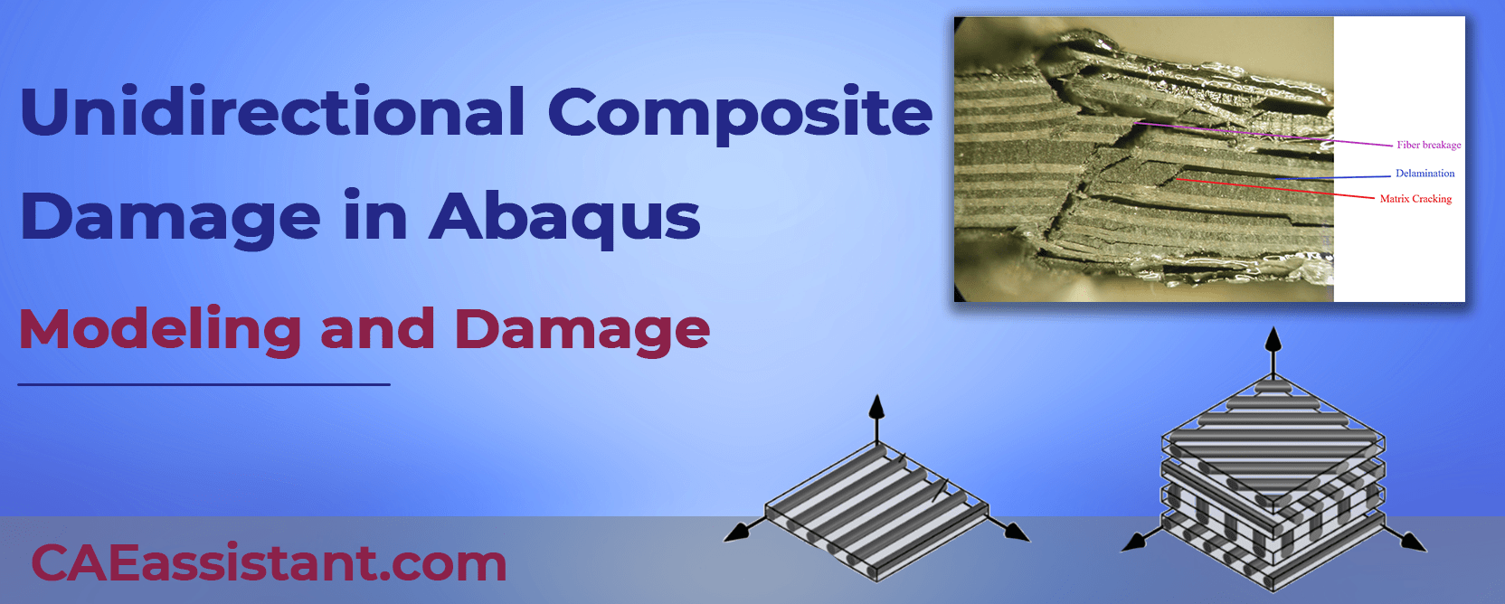
Composite damage refers to flaws or defects in materials like unidirectional composites, where all reinforcing fibers are aligned in one direction. These materials are widely used in industries like aerospace and automotive for their excellent strength-to-weight ratio. However, when they experience damage—whether during manufacturing or use—it can weaken their performance and reduce their reliability, making the study of composite damage essential for effective design and maintenance.
Composite damage can occur in various forms, such as matrix cracking, delamination, and fiber breakage. Each type of damage impacts the material differently. For example, delamination involves the separation of composite layers, while matrix cracking weakens the resin holding the fibers together. Understanding these types and their causes is key to improving the durability and safety of composite materials in demanding applications.
In this blog, we delve into the world of unidirectional composites, exploring their unique properties and behaviors. You’ll learn about different types of damage, including how they originate and progress. Additionally, we’ll guide you through simulating composite damage using software like Abaqus, with step-by-step examples. By the end, you’ll gain insights into identifying, analyzing, and mitigating composite damage effectively.
Macro or Micro Modeling for Composite Damage Analysis? It all depends on the scope of your analysis. If you’re ready to dive into macro modeling, this tutorial package will guide you step-by-step through the process. Learn how to model composite damage in Abaqus from the ground up with 5 hands-on examples tailored to unidirectional composites.
 |
|
1. What is unidirectional Composite?
A unidirectional composite is a type of composite material where the reinforcing fibers are all aligned in one direction. This is in contrast to woven composites, where the fibers are crisscrossed in a weave pattern.
The main advantage of unidirectional composites is that they offer very high strength and stiffness in the direction of the fibers. This is because all the fibers are working together to resist force in that direction. However, they are weaker in other directions.
Unidirectional composites are often used in applications where high strength-to-weight ratio is important, such as in aerospace and automotive components.
unidirectional composite
2. Unidirectional composite material properties
Unidirectional composite materials, like carbon fiber reinforced polymers (CFRP), are crucial for engineering applications due to their exceptional strength-to-weight ratio and stiffness. However, their unique properties require specific attention when modeling their behavior in Abaqus software.
Key takeaway: Accurately defining the Unidirectional composite material properties is essential for simulating unidirectional composite damage in Abaqus.
These properties fall into two main categories:
- Elastic properties: Young’s modulus, Poisson’s ratio, and shear modulus define the material’s response to deformation under load.
- E11: Longitudinal elastic modulus (along the fiber direction)
- E22: Transverse elastic modulus (perpendicular to fiber direction)
- ν12: Longitudinal Poisson’s ratio
- G12: Longitudinal shear modulus
- ν23: Interlaminar Poisson’s ratio (due to transverse isotropy, E33 = E22, ν13 = ν12, and G13 = G12)
- Strength and damage properties: These include tensile and compressive strengths, fracture toughness, and damage initiation criteria. They govern the material’s resistance to failure and the onset of damage.
- S11+ & S11-: Tensile and compressive longitudinal strength (along the fiber direction)
- S22+ & S22-: Tensile and compressive transverse strength
- S12 & S13: In-plane and transverse shear strength
- Additional properties for damage modeling (refer to Abaqus documentation)
Transverse Isotropy:
Unidirectional composites are assumed to be transversely isotropic, meaning properties are the same in all directions perpendicular to the fibers. This reduces the number of independent material constants needed.
Data Availability:
There are two common scenarios for characterizing unidirectional composites:
Limited Lamina Data:
Missing data points are often ν23 (interlaminar Poisson’s ratio) and S23 (transverse shear strength).
Typical values (e.g., ν23 = 0.5 for carbon fiber) can be used with engineering judgement.
Helius Composite Material Database can be a resource for similar materials.
No Lamina Data:
Micromechanics methods can be used to derive properties from fiber and matrix properties.
Analytical calculations (using equations) or finite element analysis (FEA) simulations can be employed.
Analytical methods are faster but less accurate and have limitations.
FEA simulations are more accurate but require specialized software.
By understanding and accurately defining these properties in Abaqus, engineers can create reliable models that predict the behavior of unidirectional composites under various loading conditions. This ultimately leads to better design decisions and improved product performance.
3. Introduction to Composite Damage
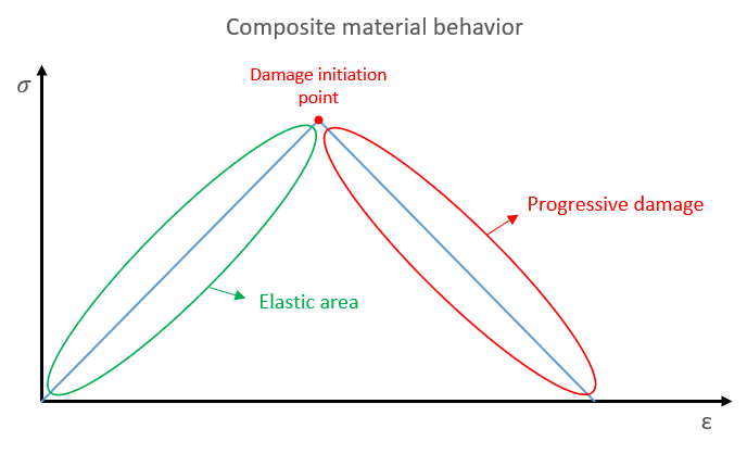
Like any structure, composites take damage as well due to the manufacturing process or in-service. Composite material behavior is different compared to other common materials. It has bilinear behavior; just take a look at the stress-strain diagram in the figure below to better understand. When a composite material is subjected to a loading condition that passes the elastic area, it reaches the “damage initiation” point; if the loading condition continues, the damage will propagate, and we have the “progressive damage” area, and the damage might propagate till the composite fails. To run a correct composite analysis, it is crucial to know all composite damage types and their effects on composite materials.
Stress-strain curve for composite materials
In the FEM simulation, we must define the “damage initiation” point and the “progressive damage” area; to do so, there are different theories that come in, such as Hashin damage criteria, Tsai-Wu, Tsai-Hill, Puck, … .
3.1. Causes of Composite damage
In comparison to metals, composites’ damage mechanisms are less well known. Composite materials and structures are susceptible to defects, whether they appear during material processing, component fabrication, or in-service use. Understanding how the damage or defect affects the structural integrity of the composite component is crucial to determining how critical the defect is. If we can somehow determine these damages and tend to them in time, the maintenance cost would be severely decreased. Also, our design will be better and well-optimized.
The composite damages can be classified into two levels:
3.1.1. Composite damage during manufacturing
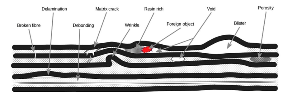
Anomalies caused by processing errors like porosity, microcracking, and delaminations are examples of manufacturing damage. Inadvertent edge cuts, scratches, surface gouges, impact damage, and damaged fastener holes are also included. Manufacturing flaws consist of:
In the Beginning of this tutorial we will see: the essentials of composite damage, from its definition and key theories to element limitations, custom criteria, and using damage results for further simulations.
- Voids
- Air bubbles
- Delamination
- Resin starved areas
- Resin rich areas
- Wrinkles
- …
Composite damage during manufacturing [Ref]
Porosity, or the existence of a void in the matrix, is the most typical one. Incorrect or ineffective curing parameters may be to blame for the porosity. Another production flaw is the inclusion of foreign bodies in the matrix, which can be anything from greasy fingerprints to a backing film.
3.1.2. In-service damage of composites
It’s true that the composite structures have sufficient strength and stiffness but like other structures, they may get damaged during the service. The damages could be caused by impact, low resistance to the service environment, overloading, Staff carelessness, etc.
In-service damages include:
- Impact damage
- Fatigue
- Matrix cracking
- Delamination
- Fiber breackage
- …
Service flaws in composite structures are typically caused by impact damages. Delamination is the most frequent impact-related damage. Delamination occurs when layers in a laminated composite are split, creating a mica-like structure with a considerable loss in mechanical properties. Delamination is the separation of the laminate at the boundary between two layers as a result of shock, impact, or repeated cyclic pressures. Individual fibers can pull away from the matrix, for instance.
- Matrix Cracking
Matrix cracking occurs when tiny cracks form within the resin, which holds the reinforcing fibers together. These cracks typically form due to:
- Tensile stresses: Forces that stretch the composite perpendicular to the fibers.
- Temperature fluctuations: Sudden changes in temperature can cause the resin and fibers to expand or contract at different rates, leading to cracks.
- Impacts: External hits or blows can also cause cracks in the matrix.
Matrix cracking compromises the integrity of the composite by weakening the resin and reducing its ability to transfer stress between the fibers.
- Delamination
Delamination refers to the separation of layers (plies) in laminated composites. This can be triggered by:
- Out-of-plane stresses: Forces acting perpendicular to the composite layers.
- Impacts: Strikes can cause layers to peel apart.
- Matrix cracks: Cracks in the resin matrix can spread, leading to layer separation.
- Manufacturing defects: Poor bonding between layers during production can make the composite more prone to delamination.
When delamination occurs, the load-bearing capacity of the composite significantly drops, making it a critical failure mode.
- Fiber Breakage
Fiber breakage happens when the reinforcing fibers inside the composite fracture due to excessive stress. This typically results from:
- High tensile loads: Stretching forces that exceed the strength of the fibers.
- Impacts or overloading: Forces beyond what the material is designed to handle.
Once the fibers begin to break, the composite’s ability to bear loads is significantly reduced, leading to potential structural failure.
- Fiber Pull-Out
Fiber pull-out occurs when the fibers are pulled from the resin matrix rather than breaking. This can happen if the bond between the fibers and the matrix is weak, which may result from:
- Manufacturing defects: Inadequate bonding between fibers and resin during production.
- Mechanical stress: Load-induced stress that weakens the fiber-matrix bond.
Although fiber pull-out can dissipate some energy during an impact, it also signals the material’s inability to effectively transfer loads, leading to failure.
- Interfacial Debonding
Interfacial debonding refers to the loss of adhesion between the fibers and the resin. This can be caused by:
- Mechanical loads: Forces that weaken the bond between fibers and matrix.
- Thermal stresses: Temperature changes can lead to differences in expansion between the fibers and resin, causing debonding.
- Environmental factors: Exposure to moisture or chemicals can also weaken the bond.
When debonding occurs, the composite loses its ability to transfer stress effectively, leading to a reduction in its mechanical performance.
- Porosity
Porosity refers to the presence of air pockets or voids within the composite material. These voids often result from manufacturing defects and can:
- Weaken the overall structure.
- Increase susceptibility to other types of damage, such as cracking or delamination.
- Moisture Absorption
Composites can absorb moisture over time, which can lead to:
- Swelling and warping: Changes in the material’s dimensions.
- Loss of strength: Water ingress can weaken both the resin and the fibers, compromising the material’s load-bearing capacity.
- Chemical Exposure
Certain chemicals can degrade both the resin and fibers in composites. This degradation can lead to:
- Loss of strength: Reduced ability to bear loads.
- Cracking: Chemical reactions that weaken the matrix or fibers.
- UV Radiation
Ultraviolet (UV) radiation from sunlight can break down the resin in composites over time, leading to:
- Cracking: Surface cracks due to resin degradation.
- Loss of mechanical strength: Weakened structural integrity.
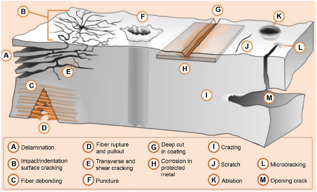
Composite Damage types [Ref]
Analysis of composites and determining the defects and damages so that the structure can keep working properly and lower the cost of maintenance is the engineer’s duty. With the help of Computer-aided engineering (CAE) and the finite element method (FEM), the composite analysis is done in the best way possible. Composite simulation is a special skill that can be achieved by our training packages.
 |
⭐⭐⭐ Free Abaqus Course | ⏰10 hours Video 👩🎓+1000 Students ♾️ Lifetime Access
✅ Module by Module Training ✅ Standard/Explicit Analyses Tutorial ✅ Subroutines (UMAT) Training … ✅ Python Scripting Lesson & Examples |
3.2. Factors influencing damage in composite materials
The damage susceptibility and severity in composite materials can be influenced by a wide range of factors, broadly categorized into:
Material factors:
- Fiber type and properties: Different fibers (e.g., carbon, glass, aramid) have varying strengths, stiffnesses, and fracture toughness, impacting damage resistance.
- Matrix type and properties: Resins differ in toughness, adhesion to fibers, and environmental resistance, influencing damage initiation and propagation.
- Fiber-matrix interface: Strong bonding between fibers and resin is crucial for stress transfer and resisting delamination.
- Microstructure and defects: Imperfections like voids, porosity, and resin-rich areas act as stress concentrators, promoting damage initiation.
Manufacturing factors:
- Processing parameters: Cure temperature, pressure, and time greatly influence fiber alignment, void content, and matrix properties, affecting damage resistance.
- Surface quality: Poor surface finish can act as initiation sites for cracks and delamination.
- Presence of impurities: Contaminants can weaken the bond between fibers and matrix, promoting debonding and matrix cracking.
5 Hands-On Workshops: Master composite damage modeling in Abaqus with five practical examples. From static analysis under complex loading to high-speed impacts on multi-layered plates and cylinders, each workshop explores unique scenarios with shell and continuum shell elements, covering both damage initiation and progression using established criteria like HASHIN.
Loading and environmental factors:
- Type of loading: Static, dynamic, fatigue, and impact loads affect damage mechanisms and severity differently.
- Magnitude and duration of loading: Higher loads and longer durations increase the risk of damage initiation and propagation.
- Temperature: Elevated temperatures can soften the matrix, weaken the bond, and accelerate damage mechanisms.
- Moisture absorption: Water ingress can plasticize the matrix, reduce strength, and trigger internal stresses leading to damage.
- Chemical exposure: Exposure to aggressive chemicals can degrade the matrix or fibers, causing localized damage and strength reduction.
Design factors:
- Geometry and thickness: Sharp corners, thin sections, and complex geometries concentrate stress, increasing damage susceptibility.
- Fiber orientation: The arrangement of fibers within the composite influences the direction and resistance to specific types of damage.
- Presence of holes and fasteners: Stress concentrations around holes and fasteners can promote damage initiation and propagation.
Understanding these factors and their interactions is crucial in selecting appropriate composite materials, optimizing manufacturing processes, and designing structures with good damage resistance for specific applications. Additionally, ongoing research explores innovative materials and design solutions to further enhance the damage tolerance of composite materials.
Now, it is time to say how to do a Composite Damage modeling in Abaqus. Here our focus would be on unidirectional composites.
4. How to do Composite Damage Simulation in Abaqus
When you want to do composite damage modeling in Abaqus, I think the real challenge lies in the material modeling and damage modeling; the geometry could be difficult sometimes but the real deal is in these two. So, let’s see how to model a single-layer unidirectional composite and laminate in Abaqus.
In Abaqus software, there are several ways to simulate composite materials. Here, we introduce the best one.
You can simulate composite materials using one of the three elements Solid, Continuum Shell, or Shell. Remember that unidirectional fiber composites are typically assumed to be orthotropic.
Example Table you could use. click on them to have access to their tutorial.
| Geometry | Loading | Element type |
| Holed Composite plate | Non-uniform loading | Shell element |
| Holed Composite plate | Non-uniform complex loading | Continuum shell element |
| Multilayer composite cylinder shell | Impact of a bullet | Shell element |
| Multi-layered composite plate | High-speed impact | Shell element |
| Composite plate | Impact | Shell element |
4.1. Composite Elastic Properties
First, you need to define the Elastic properties of the composite. When you do that, you need to define the type of elastic properties, Engineering Constants, Lamina, and Orthotropic.
In the table below you’ll see the difference between them.
| Element type | Elastic material type | Description |
| Shell, Continuum shell | Lamina | Under plane stress conditions, such as in a shell element, only the values of E1, E2, Nu12, G12, G13, G23 are required to define an orthotropic material. |
| Solid | Engineering Constant | Linear elasticity in an orthotropic material is most easily defined by giving the “engineering constants”: the three moduli E1, E2, E3; Poisson’s ratios
ν12, ν13, ν23; and the shear moduli G12, G13, and G23 associated with the material’s principal directions. |
| Solid | Orthotropic | Elasticity by Specifying the Terms in the Elastic Stiffness Matrix |
4.2. Composite Layup Tool
After that, you need to use the Composite layup tool “”. When you use this tool depending on your element type (Shell, Continuum shell, or solid) you need to choose one of three options you see in the picture below.
Composite layup element selection
If you select Solid or Continuum shell, the settings would be as follows, which I explain to you in an example:
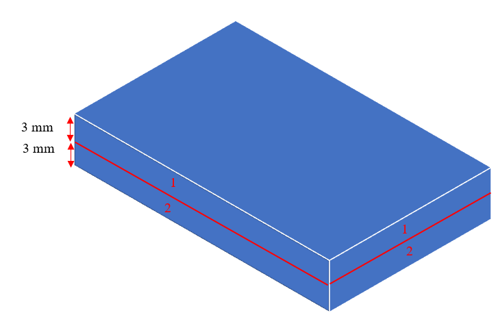
Imagine we have a 4-layer composite laminate like this [90o, 30o, 40o, 45o]. we have 2 elements in the thickness as depicted below and the thickness of the composite is 6 millimeters.
Composite laminate orientation
Now, we need to set these layers in the Edit Composite Layup window as depicted below. In element number 1 the thickness of lamina 90 and 30 are 1 and 2 millimeters, respectively; so, the whole thickness of element number 1 is 3 millimeters and therefore, the element relative thickness of each layer in this element equals 1/3 and 2/3, respectively. Same logic for other layers.
| Element number | Lamina orientation | Thickness (mm) | Element Relative Thickness |
| 1 | 90 | 1 | 1/3 |
| 30 | 2 | 2/3 | |
| 2 | 40 | 2 | 2/3 |
| 45 | 1 | 1/3 |
Edit Composite layup window for Solid elements
After that, you need to assign the material orientation, and the composite material modeling is completed. See it in an example: Abaqus composite modeling.
Now, to apply the damage, first you need to know which criteria you want to use. Here is the list of some damage criteria in Abaqus:
- Johnson-Cook damage model
- Tsai-Hill failure criterion
- Tsai-Wu failure criterion
- Puck criterion
- …
In the Abaqus simulation, regardless of which criterion we choose, we must define the “damage initiation” point and the “progressive damage” area. Next, we need to define the analysis step, boundary conditions, mesh, and start the job.
Don’t worry, we have tutorial packages to help you out how exactly you should procced in these simulations:
4.3. Failure Criteria for Composite Damage
To simulate the behavior of composite materials and predict damage in composites, we must use damage criteria. There are various criteria for predicting damage in composites, but some of these criteria are more accurate. We will examine some of these criteria in the following.
- Tsai-Hill criterion
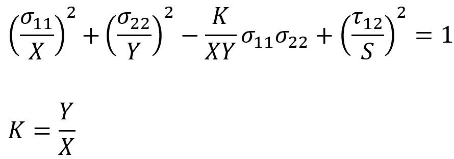
The Tsai–Hill failure criterion is a failure theory, which is widely used for anisotropic composite materials such as unidirectional composites which have different strengths in tension and compression. It allows us to predict the ultimate resistance of the least resistant ply, in the case of the plane stress.
X and Y are, respectively, the ultimate tensile strength stresses of the ply 0 ° and 90 °. S is the ultimate shear stress in plane 12 of the 0° layer.
There is therefore no rupture of the material if the prevailing stresses do not exceed one. Tsai-Hill is a failure mode independent criterion, as it does not predict how the material will fail.
- Tsai-Wu criterion
The Tsai–Wu failure criterion is a failure theory that is widely used for anisotropic composite materials that have different strengths in tension and compression.
and
are the stress components
-
are material coefficients determined experimentally.
If you want to learn more about the Tsai-Hill and Tsai-Wu criteria, you can use our products or this article: “Introduction to Tsai Hill Failure Criterion & Tsai Wu Failure Criterion”.
- Hashin criterion
The Hashin Damage Criterion is a failure theory designed to predict different types of damage in composite materials such as fiber-reinforced composites. This criterion distinguishes between fiber and matrix failure, providing a more detailed failure mechanism prediction for composites compared to traditional criteria like the Tsai-Hill and Tsai-Wu.
The Hashin criterion is available for both plane stress and three-dimensional stress. Here we briefly examine the two-dimensional case.
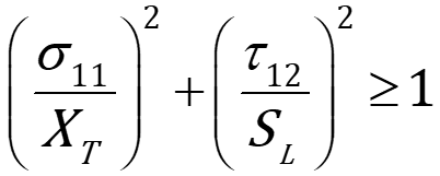
For fiber tension, the criterion is:
Where:
is the longitudinal stress in the fiber direction.
is the longitudinal tensile strength of the fibers.
is the shear stress.
is the longitudinal shear strength
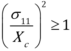
For fiber compression:
Where is the longitudinal compressive strength of the fibers.
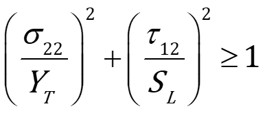
For matrix tension, failure is governed by:
Where:
is the transverse normal stress (stress in the direction perpendicular to the fibers).
is the transverse tensile strength of the matrix.
For matrix compression, failure occurs if:
Where:
is the transverse compressive strength of the matrix.
is the transverse shear strength.
This criterion is very suitable for simulating unidirectional composites in Abaqus. It also has the ability to detect the onset of damage and progressive failure. For more information about the Hashian criterion, three-dimensional case relations, and how to use it in Abaqus, see “What is Hashin Failure Criteria? | Hashin Damage in Abaqus”.
5. Conclusion
This article explored the concept of composite damage, focusing on unidirectional composites widely used in industries like aerospace and automotive. These materials, while valued for their strength-to-weight ratio, are prone to various types of damage that can impact their performance and longevity, making it crucial to understand and analyze these flaws.
The blog began by introducing the types of composite damage, such as matrix cracking, delamination, and fiber breakage, along with their causes during manufacturing or in-service use. Next, it examined the factors influencing damage, including material properties, manufacturing processes, and environmental conditions. Finally, it discussed simulating composite damage in Abaqus, highlighting techniques for defining elastic properties, damage initiation criteria, and failure models like Hashin and Tsai-Wu.
In conclusion, this article provided a clear understanding of composite damage mechanisms, their implications, and effective ways to analyze and mitigate them using computational tools. Such knowledge is essential for improving the design, maintenance, and reliability of composite materials in advanced engineering applications.
Now, if you need to know how to model damage in composite materials, especially in unidirectional and laminate composites, you should see it in action, which I recommend our complete tutorial. Trust me you won’t regret it.
It would be helpful to see Abaqus Documentation to understand how it would be hard to start an Abaqus simulation without any Abaqus tutorial.
The CAE Assistant is committed to addressing all your CAE needs, and your feedback greatly assists us in achieving this goal. If you have any questions or encounter complications, please feel free to share it with us through our social media accounts including WhatsApp.


