Additive Manufacturing Simulation Ultimate Guide
Did you know that achieving flawless, high-performance 3D-printed parts starts long before the printer even hums to life? The secret lies in cutting-edge digital simulations. These powerful tools model how materials behave under heat and stress during the printing process, allowing engineers to predict and prevent potential issues. The result? Precise, reliable parts without the trial-and-error guesswork.
3D printing simulations serve as a bridge between design and reality. They allow manufacturers to anticipate issues like thermal stress, warping, and material inconsistencies, offering solutions to optimize production. By analyzing how materials behave under specific conditions, simulations ensure reliability and quality in industries where accuracy matters most, like aerospace and medicine.
In this blog, we’ll explore how simulations enhance 3D printing. You’ll learn about key challenges in simulating processes, the role of advanced tools like Finite Element Analysis (FEA), and practical applications of software like Abaqus, ANSYS, and Simufact. Whether you’re a manufacturer or an enthusiast, this guide will help you understand the critical role of simulations in achieving superior 3D-printed parts.
 |
🎧 Prefer Listening Over Reading? 🎧 In our latest podcast episode, we dive into the essentials of additive manufacturing simulation.
Tune in and get the full story without reading the entire article. |
Related Packages
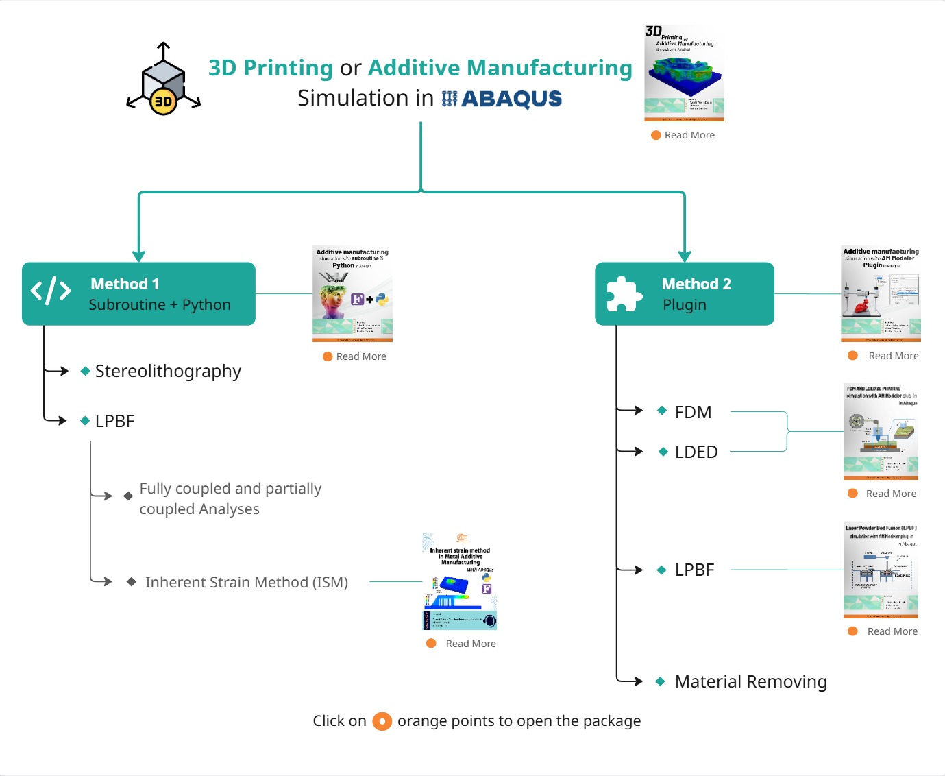
You may need a dedicated tutorial for your specific requirements. We offer a wide range of simulation tutorials covering various real-world problems. To explore our products and identify the most suitable package for your needs, please refer to the diagram below.
Please note that in Additive Manufacturing simulations, different methodologies may exist, but many of them share similar simulation procedures.
To make sure the selected package meets your expectations, feel free to speak with our experts via the website’s online chat. Our engineers will help you find the most appropriate package for your needs.
1. Introduction to Additive Manufacturing Simulation: Understanding the Basics of 3D Printing Simulation
3D printing is revolutionizing manufacturing by allowing the creation of intricate and customized designs. However, achieving the best results requires more than just advanced equipment; a deep understanding of the process is essential. This is where additive manufacturing simulation plays a key role. Simulation helps predict and optimize outcomes, enabling manufacturers to avoid print failures and reduce rejections due to geometric issues, ultimately saving time and costs. It offers insights into the physics of the manufacturing process, allowing for the prediction of microstructural characteristics and refinement of production parameters for improved quality and precision.
In this blog section, we’ll explore the crucial role of simulation in additive manufacturing, discussing its importance, challenges, and the innovative potential of techniques like Finite Element Analysis (FEA).
1.1. Why Additive Manufacturing Simulation is Critical for Success in 3D Printing
Simulation is like a fun virtual playground where we can play around with ideas and troubleshoot potential issues before they actually happen during printing! It helps us catch problems like material warping or bonding failures and suggests easy solutions, such as adjusting temperatures or layer thickness. By using simulation, manufacturers can get a better handle on production risks and reduce the chances of failure, making it a key player in ensuring quality and reliability in additive manufacturing.
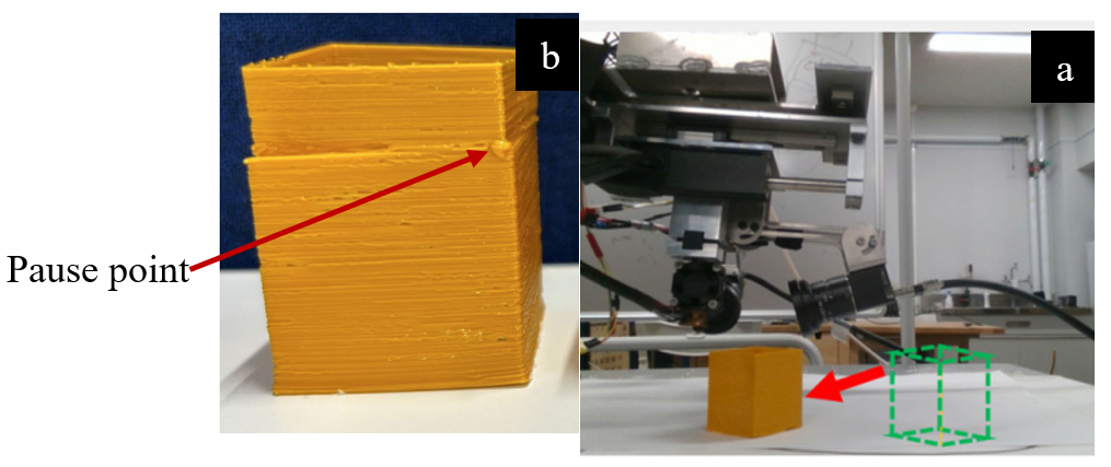
Imagine you’re printing a high-precision part, like a medical device or a gear. Even the tiniest misalignment can turn that piece into something completely useless (fig1)! But with simulation, we can foresee these little issues and fine-tune the printing path on the fly, ensuring everything is spot on.
Figure 1: (a)moving printer piece (b) restart after pausing the printer [Ref]
Plus, simulations can give us insights into how materials behave at a microscopic level, opening the door to clever tweaks. We might adjust the print orientation, design changes, or add custom support structures to enhance the final product. It’s all about connecting design and execution, giving us control over how materials respond to heat and other stresses. In industries like aerospace and medicine, where every little detail counts, simulations help ensure the final product performs beautifully in the real world while keeping the risk of defects or failures to a minimum. Sub-pixel accuracy—a capability to make adjustments finer than a single pixel on the camera—ensures flawless precision.
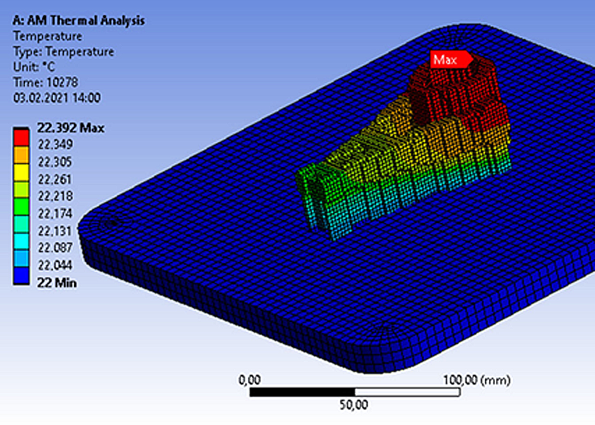
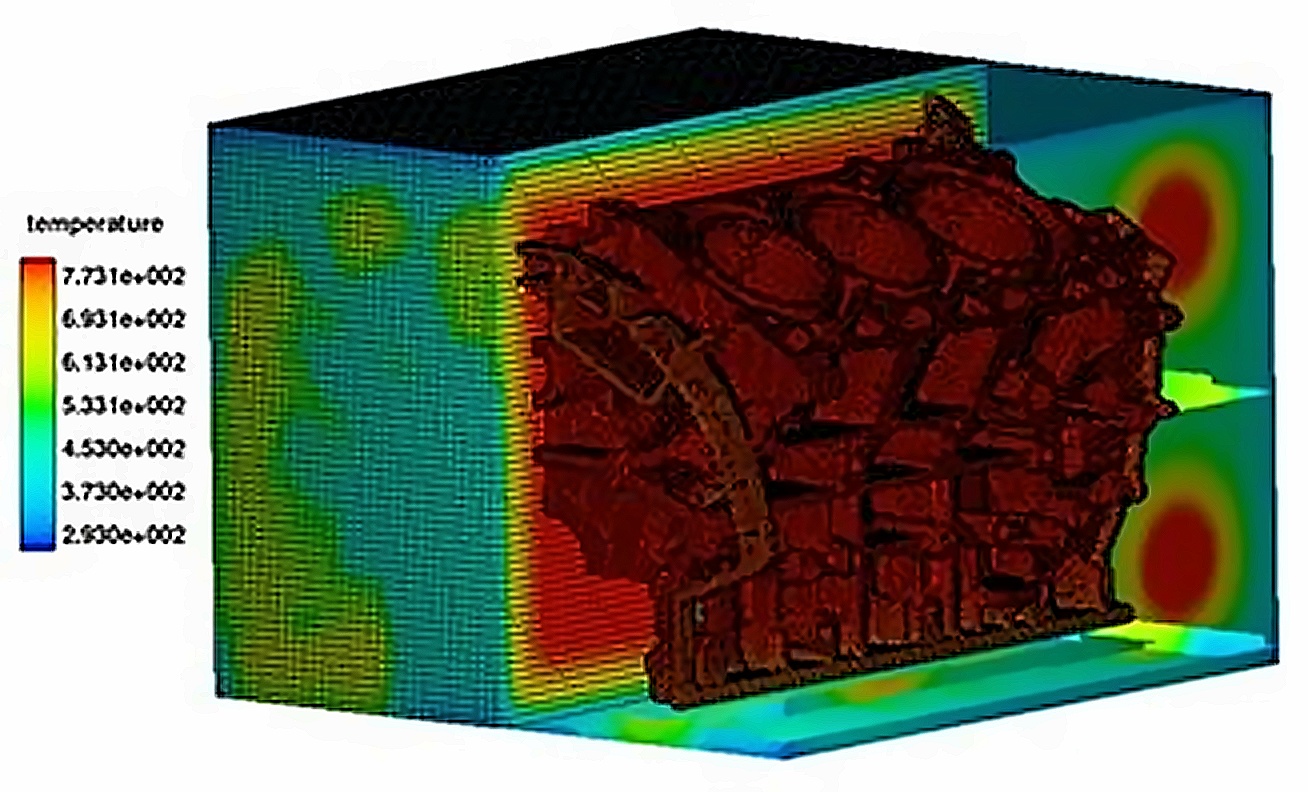
Let’s make another example to illustrate the importance of simulation further. Imagine you are printing a metallic component for use in aerospace applications. Metallic materials tend to deform as they cool, causing thermal stress. This stress can lead to micro-cracks or even complete failure of the printed part. Simulation enables us to predict the thermal behavior of the material. For instance, we can use advanced software to model the temperature distribution throughout the printing process. This information allows us to make adjustments—such as slowing down the printing speed or fine-tuning the nozzle temperature—to prevent thermal stresses from occurring.
The result? A high-quality part, free of cracks or defects, that can safely be used in sensitive environments like aerospace or medical fields.
Speaking of 3D printing simulation of metallic parts, we’ve got the perfect tutorial to help you master “Inherent strain method in metal additive manufacturing simulation“. Check it out!
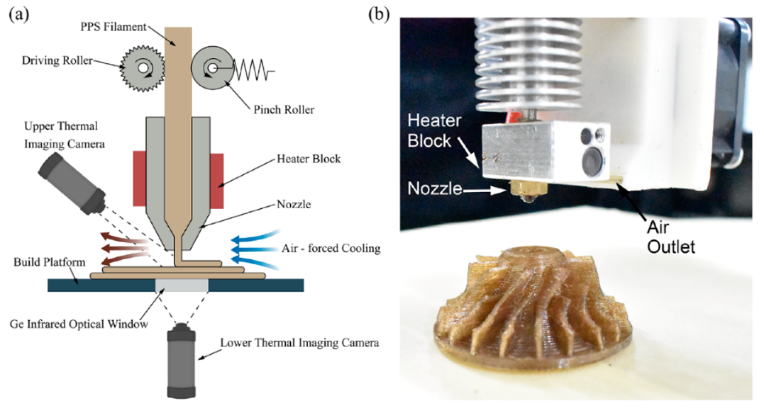
Figure 2 available via license: Creative Commons Attribution 4.0 International: Thermal analysis results in 3D printing simulation [Ref]
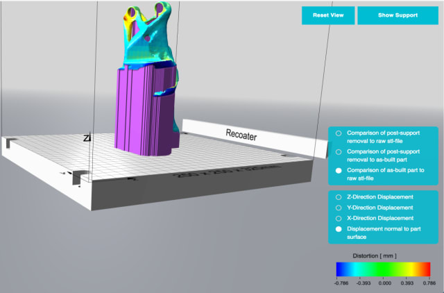
Now that we’ve explored the significance of simulation in addressing problems and improving the 3D printing process, it’s logical to move on to the key challenges in simulating 3D printing processes. These challenges include limitations and the complexity of geometric designs, and the accuracy of input data. In the next section, we’ll dive deeper into these issues.
1.2. Key Challenges in 3D printing Simulation
3D printing simulation faces key challenges that impact its accuracy and reliability. These issues arise from the complexity of the printing process, material diversity, and dynamic conditions during production.
- Multi-Physics Complexity
One major challenge is the multi-physics nature of the process, requiring precise inputs like thermal properties, material behavior, and particle geometry. Rapid temperature changes during printing can cause defects such as warping, cracking, or residual stresses, making accurate predictions difficult.
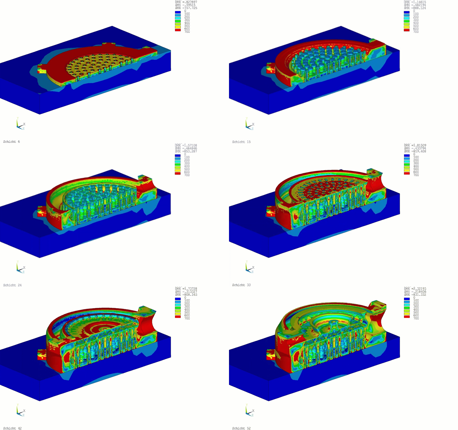
For example, Figure 3 highlights areas of high thermal stress (red zones) caused by uneven cooling during printing. These stress zones are critical in understanding potential defects in the final product.
Figure 3: thermal stress analysis highlights areas of high stress (red zones) caused by uneven cooling [Ref]
- Geometric Complexity
Another challenge lies in the geometric intricacy of 3D-printed designs. Intricate shapes, overhangs, and lattice structures demand advanced algorithms to simulate stress points and deformations effectively.
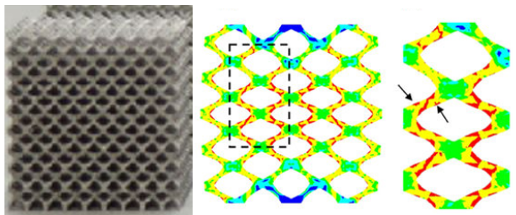
As shown in Figure 4, a lattice structure requires highly detailed simulation to predict its performance under load. Such structures, while lightweight and efficient, often pose difficulties in ensuring reliability.
Figure 4: The geometric complexity of a lattice structure requires detailed simulation to predict its performance under load [Ref]
- Material Variability
Material variability adds further complexity. Metals may develop residual stresses due to uneven cooling, while plastics are prone to warping. Obtaining accurate material data for simulations remains a significant obstacle to achieving reliable results.
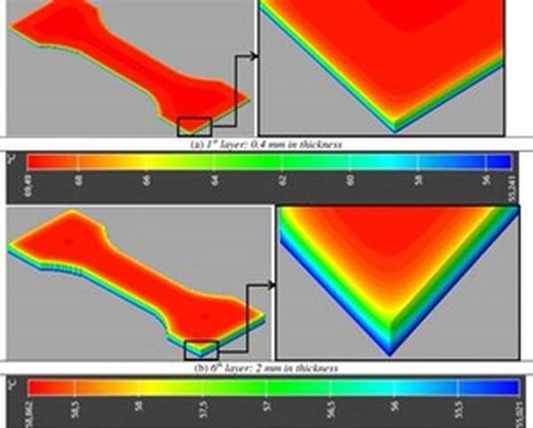
In Figure 5, a simulation of layer bonding and cooling in polymer 3D printing simulation demonstrates how materials react differently to thermal changes, highlighting the importance of accurate material modeling.
Figure 5: simulation of layer bonding and cooling in polymer 3D printing [Ref]
- High Computational Demands
Simulating 3D printing processes involves significant computational power. These simulations aim to replicate real-world conditions by modeling thermal behaviors, structural stability, and material interactions. For instance, in the case of printing a complex metal component like a turbine blade, the simulation must account for:
- Heat transfer between layers.
- Stress distribution to prevent cracking.
- Material shrinkage during cooling.
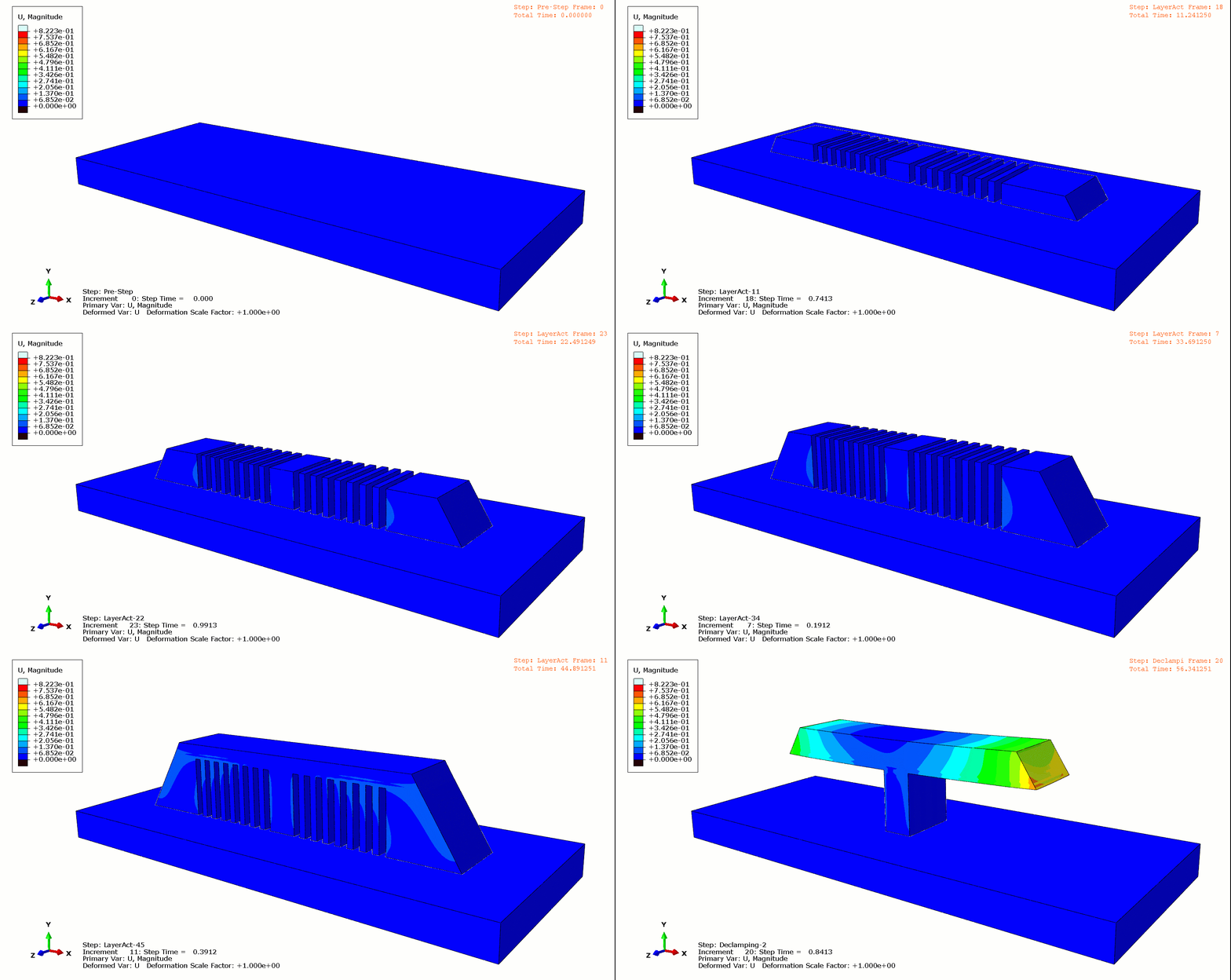
These intricate calculations often require substantial computational resources, making high-fidelity simulations costly and time-consuming. Figure 6 illustrates a thermal and stress simulation during layer loading, showing the insights achievable with adequate resources.
Figure 6: Thermal and stress simulation during layer loading [Ref]
Addressing these challenges requires advanced techniques, and this is where Finite Element Analysis (FEA) becomes crucial. FEA enables detailed modeling of thermal, structural, and material interactions, helping to predict and solve complex issues like warping and residual stress. By dividing a complex object into more minor, manageable elements, FEA provides precise insights into how each part of a 3D-printed object behaves under specific conditions. This method enhances simulation accuracy and bridges the gap between theoretical modeling and real-world outcomes.
Thermal and structural! In a FEA software such as Abaqus there is a way to have both of these analysis called Sequential thermomechanical analysis. This means the thermal analysis must be done first, and its results will be applied to the structural analysis. How you can learn it? Very easy just by watching this tutorial “Additive manufacturing simulation with Abaqus subroutine & python” or this one “Additive manufacturing simulation with Abaqus AM modeler plugin“. The difference is one of them using scripting and the other uses a plug in called the AM Modeler.
In the next section, we’ll delve deeper into how FEA transforms the additive manufacturing simulation, enabling better results and more reliable 3D printing.
1.3. The Role of Finite Element Analysis 3D Printing Simulation
When it comes to understanding the mechanical properties of materials, traditional stress-strain curves have been a go-to tool. They’re perfect for uniform, homogeneous materials—but 3D-printed parts are a whole different story. With their intricate internal structures, like honeycomb or lattice patterns, these parts behave in anisotropic ways, adding layers of complexity. This is where finite element analysis (FEA) in 3D printing (finite element analysis 3d printing) becomes essential, allowing engineers to accurately simulate and predict mechanical behavior. And when you’re dealing with critical fields like aerospace or medical equipment, where safety is everything, this challenge becomes even more important.
Engineers often take a straightforward approach in finite element analysis (FEA): they use standard mechanical properties like elastic modulus, density, and Poisson’s ratio from basic experiments. This lets them simplify the model, treating the part as if it were solid. It’s a decent way to estimate elastic behavior, but here’s the catch—real 3D-printed parts have voids and irregularities that can skew the results. That’s why it’s crucial to compare your analysis with the real-world structure to avoid surprises.
For those aiming for precision, you can model every tiny detail and void in the FEA simulation. It’s super accurate but comes with a hefty price: longer computation times and higher demands on your hardware. Simplifying the process with a mix of 2D and 3D elements sounds tempting, but it can quickly complicate things and increase the chances of errors.
Balancing accuracy and practicality is the name of the game, and understanding these trade-offs can make all the difference in your analysis.
Figure 7: A detailed FEA model of a honeycomb structure [Ref]
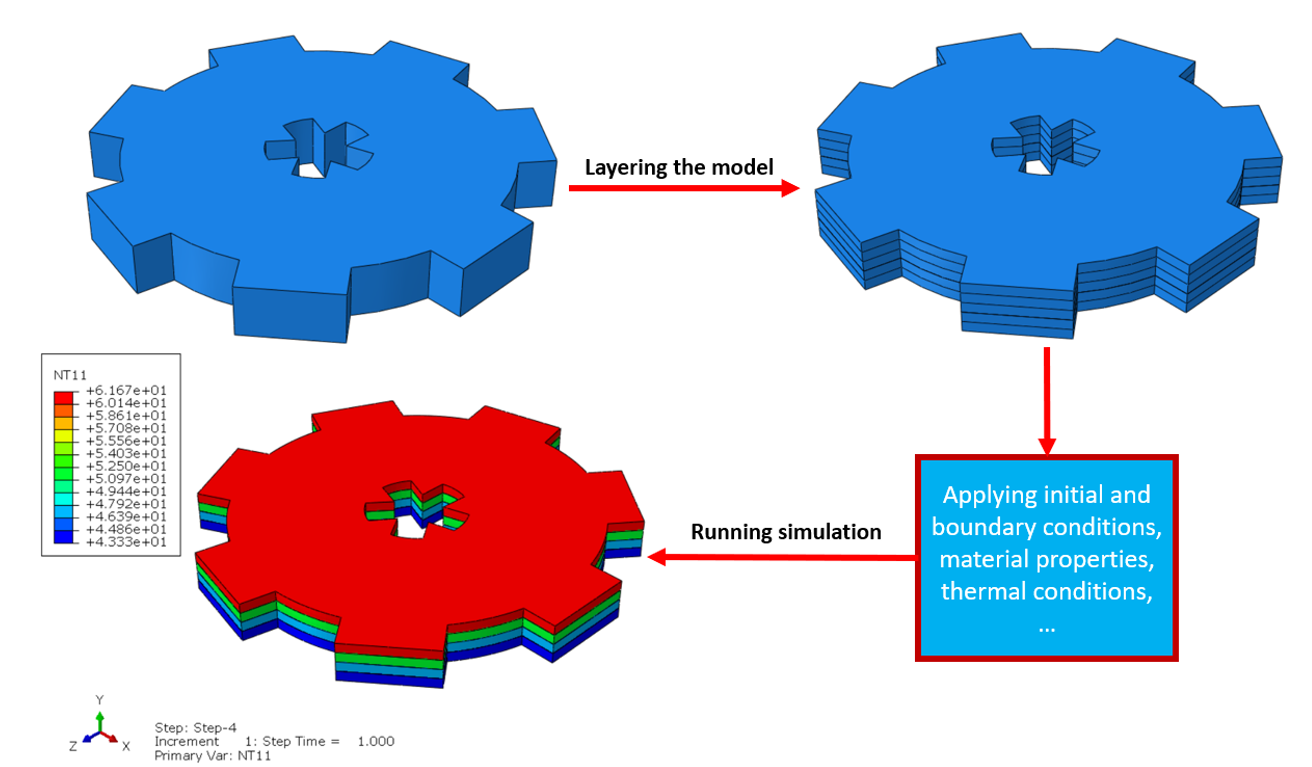
Let’s talk a little more about finite elements in simulation software. To get started with your simulation, first design your model in CAD or FEM software. Once that’s done, slice the model into thin layers and import it into the FEM software. After that, set up the required equations to handle material properties, boundary conditions, and thermal conditions based on the software settings. Finally, hit run and let the simulation do its magic!
2. Simulation Processes in Additive Manufacturing: Key Parameters Affecting 3D Printing Performance
This section, explores the foundational techniques of thermal analysis, mechanical behavior modeling, and meshing strategies in 3D printing simulation, shedding light on the science and technology behind achieving superior printed parts.
2.1. Thermal Analysis in Additive Manufacturing Simulation: Optimizing Temperature Effects on Printed Materials
One of the most crucial aspects in additive manufacturing simulation is understanding how heat is transferred within the melting zone and its surroundings. This isn’t just about a simple conduction equation; advanced methods are also used in finite element software like Abaqus to model heat sources more accurately.
For example, in simulating welding or localized melting processes, models like the Goldak heat source are commonly applied. This approach is particularly useful in 3D metal printing (especially laser-based methods). The Goldak model, which assumes an ellipsoidal heat source, provides a more realistic prediction of temperature distribution and explains how energy disperses in different directions. Its equation is given as:
Where:
- Q: total power of the heat source,
- a,b,c: dimensions of the ellipsoidal heat source,
- x,y,z: spatial coordinates.
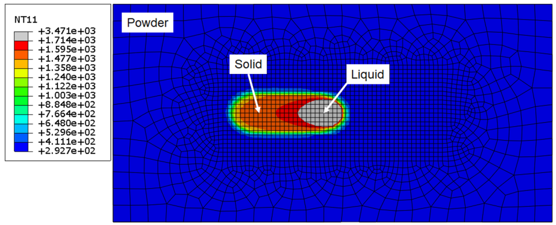
Figure 8: Goldak model in LPBF simulation [Ref]
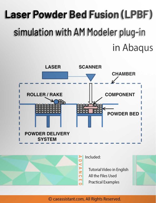
Figure 8 shows a LPBF simulation. Do you want to know learn how to do it? The Abaqus detailed LPBF tutorial using AM Modeler Plug in can teach you how.
Or you can learn the LPBF simulation using the Inherent Strain Method with detail explanation. Full tutorial about the inherent strain method theory and how to use it in Abaqus.
In finite element simulations of 3D printing, three main heat transfer methods—conduction, convection, and radiation—are typically considered. The most critical of these is conduction (Uniform Heat Source), governed by the transient heat conduction equation:
Here:
- ρ: material density,
- c: specific heat capacity,
- k: thermal conductivity,
- T: temperature,
- Q: internal heat generation,
- t: time.
This equation describes how temperature evolves over time and space. A specific case of this is Fourier’s Law, which relates heat flux to the temperature gradient:
where q represents the heat flux vector.
However, when using a focused heat source like a laser, Simpler versions of Goldak, such as Gaussian or cylindrical heat sources, are also used in some cases to approximate heat distribution over a specific material volume. Convection and radiation heat transfer usually have less impact compared to conduction. Convection, described by the equation:
Accounts for heat transfer between the part’s surface and the surrounding fluid (air or gas). Here:
- qconv : convective heat transfer,
- h: heat transfer coefficient,
: surface temperature,
: ambient temperature.
Radiation, however, becomes significant at high temperatures and is governed by Stefan Boltzmann’s Law:
where:
- qrad : radiative heat transfer,
- ϵ: emissivity of the material,
- σ: Stefan-Boltzmann constant
If the molten pool temperature is extremely high or there’s a gas flow around the printed part, these coefficients can be included in the simulation. A key point here is that if the material’s thermal properties change with temperature, they should be defined as temperature-dependent functions to improve the simulation’s realism. It’s also better to model the process layer by layer like the Layered Heat Deposition model, activating each layer at its respective time step. This ensures the gradual heating and cooling effects on underlying layers are captured accurately.
Such approaches can be implemented in Abaqus, ANSYS, or other finite element software, providing insights that help in decisions like laser scan speed, layer thickness, build orientation, and even the design of cooling systems. By understanding how heat distributes over time, engineers can minimize residual stresses and distortions while preventing micro-cracks or poor layer adhesion. This is where the satisfaction of a well-executed simulation comes in—starting with a few simple thermal parameters and progressively incorporating more advanced methods like the Goldak model to accurately predict how the material responds to laser heat or other energy sources.
Figure 9: effect of thermal processing and heat treatment conditions on 3D-printed samples [Ref]
Ultimately, this combination of scientific understanding and practical application improves the quality of 3D-printed parts while reducing costs associated with trial and error. It’s this powerful mix of precision and efficiency that makes thermal analysis in 3D printing simulations so exciting for both enthusiasts and engineers alike.
2.2. Mechanical Stress and Strain Analysis in Additive Manufacturing: Ensuring Structural Integrity
In the analysis of stress and strain in 3D printing simulations, we can delve into a more detailed examination of material behavior using advanced equations. The first step is extending Hooke’s Law to three dimensions. Instead of a simple linear relationship, we use stress and strain tensors:
where:
is the stress tensor,
is the strain tensor,
is the stiffness matrix for anisotropic materials.
This equation allows us to consider the effects of print directionality and layer-by-layer structure in a 3D printer. For anisotropic materials, the stiffness matrix is represented as a 6×6 matrix, capturing different parameters based on the printing direction. In simulation software like ANSYS, Abaqus, or SolidWorks Simulation, detailed mechanical behavior is analyzed using the Finite Element Method (FEM). The equilibrium equations in FEM are written as a set of algebraic differential equations:
where:
- K is the global stiffness matrix assembled from individual element stiffnesses,
- u is the vector of nodal displacements,
- F is the vector of applied nodal forces.
These equations are solved using specified boundary conditions and loading scenarios. In nonlinear analyses, the equations might depend on time or deformation extent, necessitating iterative methods like Newton-Raphson:
Here, is the residual force based on the current estimate
, and
updates the displacement.
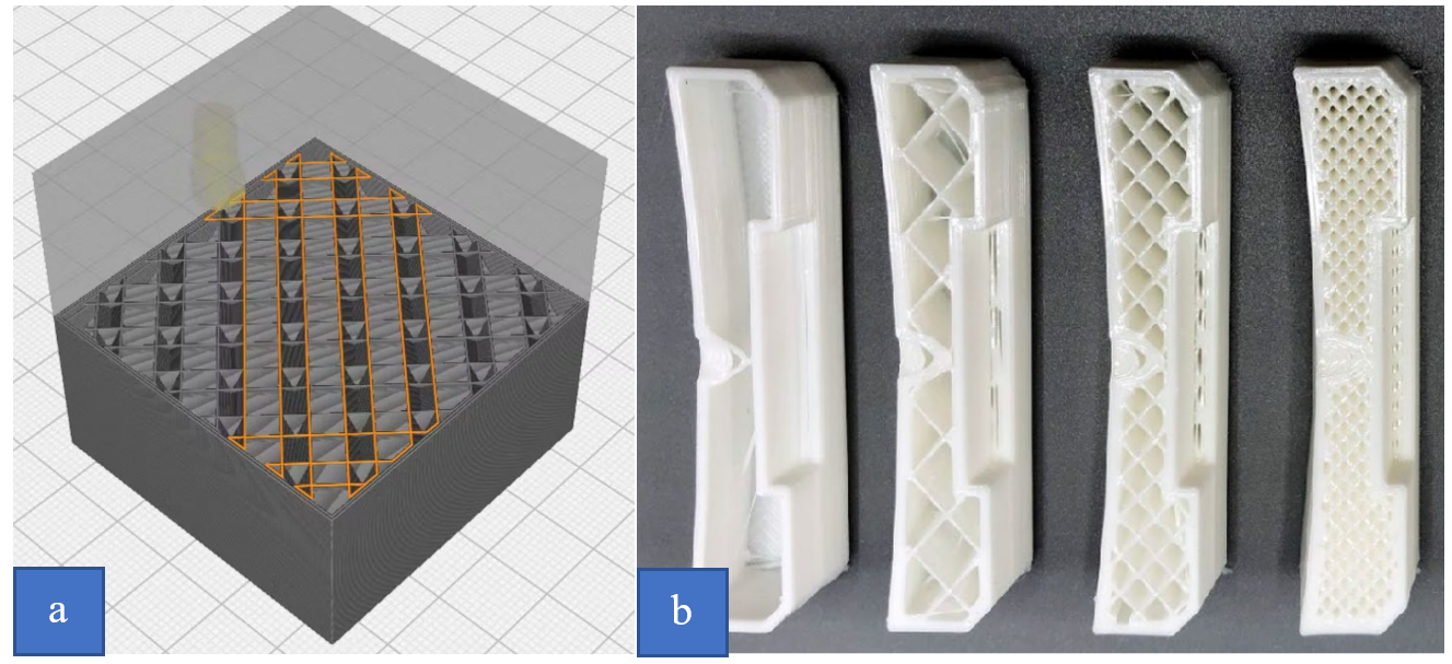
Beyond mechanical equations, the infill pattern and material engineering parameters play a key role in determining the final part’s behavior. The infill pattern defines how the material is distributed inside the part, directly affecting stress distribution and deformations. In simulation software, you can model the interior of the part as a network of finite elements representing the infill pattern.
Figure 10: a) The simulation infill pattern in CAE software b) The infill patterns in the 3D printer [Ref]
Imagine a simple lattice network where each cell has a thickness of t and spacing d. When modeling such a structure, the mechanical properties of each element are determined based on the pattern orientation and the fill fraction ϕ. We use an averaging relation for the effective modulus:
where:
is the effective modulus,
is the volume fraction of actual material in the infill pattern,
is the modulus of the solid material, and
is the modulus of the void, which is near zero.
For instance, in directions where internal beams are denser (internal structure or infill pattern of a 3D-printed object.), Young’s moduli Ex and Ey may differ from Ez. These directional differences are incorporated using the stiffness matrix Cijkl and precise assignment of mechanical properties to different elements.
Material properties and internal structure significantly influence simulation outcomes. By modeling a finite element mesh that mirrors the infill pattern, simulation software can analyze how uneven stress distributions occur based on layer directionality and internal arrangement.
For repeated loading and plastic conditions, plasticity models like J2 plasticity can be used:
Where is the deviatoric stress, and
is the current yield stress depending on the hardening parameter κ.
By incorporating these details into simulation modeling, the behavior of each layer and the interactions between infill pattern and material properties are analyzed more accurately. This approach allows designers to adjust settings like print orientation, infill pattern, and material selection to improve performance and durability in a friendly, reader-friendly manner.
2.3. Advanced Meshing Techniques for Accurate Additive Manufacturing Simulation Results
Advanced meshing techniques are crucial for capturing the exact behavior of 3D-printed parts under varying loads and temperatures. In finite element analysis (FEA), the solution to the system [K]{u}={F} depends on subdividing the model into smaller elements. Tools like ANSYS or Abaqus use adaptive meshing, which automatically refines the mesh in regions with large gradients in stress or temperature. This ensures a dense mesh only where necessary, balancing accuracy and computational efficiency. Conversely, mesh coarsening reduces element density in uniform zones, saving resources for areas prone to higher loads or thermal challenges.
Another strategy is hybrid meshing, where tetrahedral elements tackle intricate geometry, while hexahedral elements handle simpler sections. This approach enhances both speed and precision, particularly for complex 3D-printed designs. Modern software typically includes wizards to guide users in defining element sizes, boundary layers, and refinement criteria. After generating the mesh, a mesh convergence study verifies whether further refinement changes simulation outcomes significantly. This step ensures the mesh is sufficiently detailed without becoming too large to compute. By applying these advanced techniques, engineers can more accurately predict potential deformations, optimize part geometry, and avoid costly reprints in real-world 3D printing scenarios.
3. Top 3 Additive Manufacturing Simulation Software
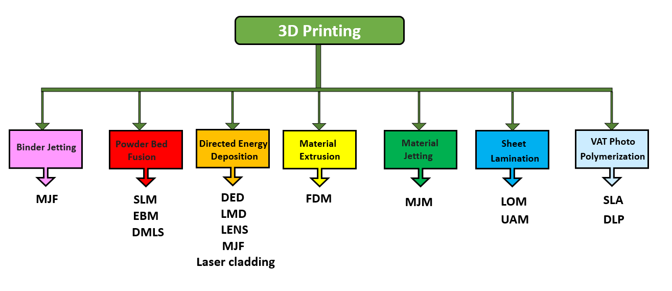
As we know, 3D printing, also known as additive manufacturing, can be categorized based on how each material layer is formed and solidified. As shown in the fig 11, these categories include Material Extrusion, Vat Polymerization, Powder Bed Fusion, Material Jetting, Binder Jetting, etc. Although each technique builds parts layer-by-layer, they use different processes—such as melting plastic filaments, solidifying liquid resins, or fusing metal powders under high temperatures. Understanding these distinctions is key to appreciating why certain simulation tools are more suited to specific 3D printing methods.
Figure 11: 3D printing Category
Let’s address a common question: “How is a 3D printing simulation performed?” The process depends on the software being used, but the basic steps are similar across all Additive Manufacturing Simulation Software. First, the model to be simulated must be created in a CAD or FEM software. Next, the model is sliced into thin layers and imported into the FEM software. Then, the necessary equations describing material property changes, boundary conditions, and thermal factors are applied according to the software’s settings. Finally, the simulation is run (fig 12).
Figure 12: BASICS OF 3D PRINTING SIMULATION
In this section, we will explore the various environments of the most commonly used types of simulation software on the market, which are Abaqus, ANSYS, and Simufact. Additionally, we will analyze the properties of materials, the arrangement of layers, boundary conditions, temperature variations, and the equations governing these properties.
3.1. 3D Printing Simulation in Abaqus
Abaqus is a powerful simulation software, ideal for tackling complex thermomechanical problems involving phase changes and large deformations. Widely used in aerospace and automotive industries, it excels at high-fidelity modeling, combining heat flow with stress and strain analyses.
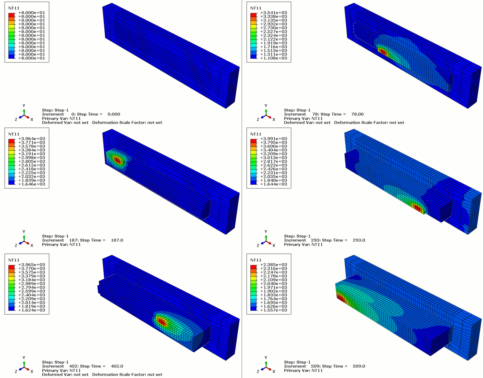
Figure 13: 3D printing simulation with Abaqus
The 3D printing simulation in Abaqus is done via two methods:
- Using python scripting and subroutine: As previously mentioned, the model must first be sliced into layers. This can be done using CAD software, which is preferable, or directly within Abaqus. Each layer is printed (activated) during each step of the process. Additionally, when a layer is printed, its corresponding boundary conditions, material properties, and other factors must be applied according to the governing equations of the problem. These equations define variations in material properties, thermal conditions, and more. The tasks involved are handled through a combination of Python scripting and necessary subroutines. Once the inputs are provided, you simply run the Python code and wait for the analysis to finish.
Figure 14: 3D printing simulation with python
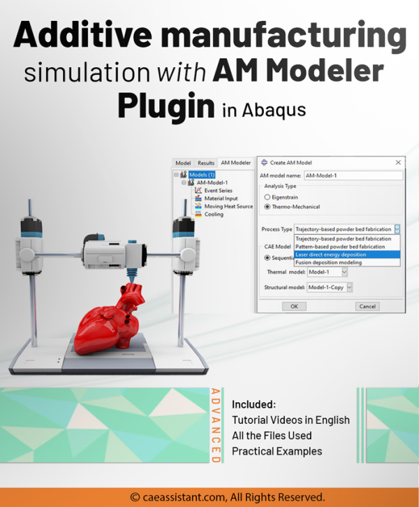
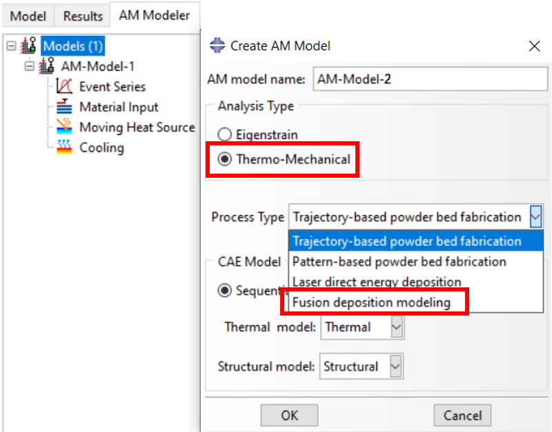
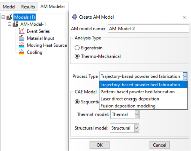
2. Using AM Modeler plug in: The “AM Modeler” plug-in for additive manufacturing simulation provides a user-friendly graphical interface that offers an efficient and scalable solution for simulating 3D printing, with minimal risk of errors. It eliminates the need for Python scripting, subroutine writing, or any other coding. All you need to do is input the necessary parameters, create a job, and start the simulation. This plug-in allows you to simulate popular 3D printing techniques such as Powder Bed Fusion (PBF), Direct Energy Deposition (DED), and Material Extrusion (ME).
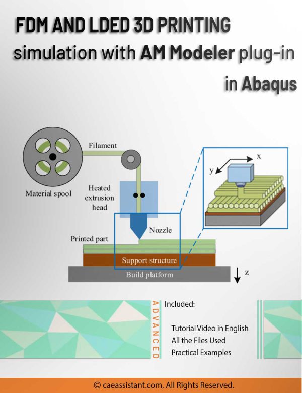
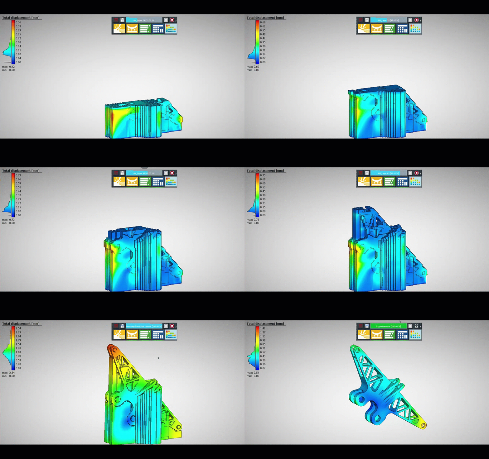
Figure 13 simulation is an example of FDM simulation using Abaqus with AM Modeler plug in. You can see below that there is an option specified for Fused Deposition Modeling (FDM) Process. You can learn all about it in the FDM Simulation in Abaqus tutorial.
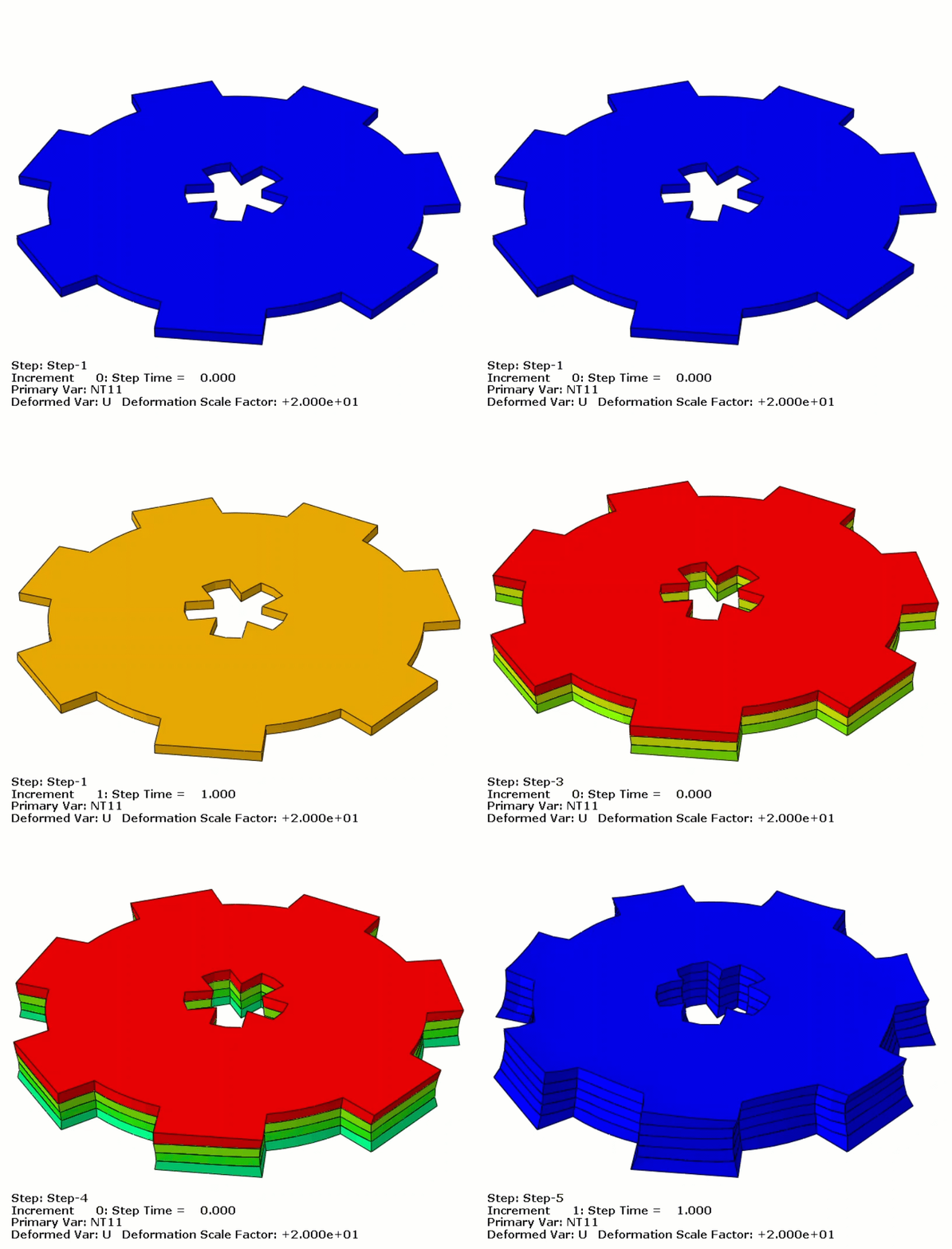
This is a stereolithography (SLA) 3d printing simulation using Abaqus with python scripting and subroutines. This is just 5 layers and the way to do this is shown in the flowchart on the left. You can learn all of these steps in our 3D printing simulation python scripting tutorial.
Discover the Inherent Strain Method in metal 3D printing (LPBF) with this step-by-step tutorial. Learn the theory and apply it with a practical Abaqus simulation using Python scripting and subroutines. All in our Inherent strain method in Metal Additive Manufacturing simulation tutorial.
Figure 15: Abaqus AM Modeler plugin
3.2. Additive Manufacturing Simulation in ANSYS
ANSYS is another robust simulation platform frequently used for thermomechanical analyses in 3D printing methods like Selective Laser Melting (SLM) and Direct Metal Laser Sintering (DMLS). Similar to Abaqus, it couples heat flow with stress-strain analysis to predict residual stresses and distortions caused by fast heating/cooling cycles. Additionally, ANSYS supports advanced material models, including anisotropic behavior for composites or temperature-dependent properties for metals.
With L being the latent heat of fusion and f(T) transitioning from 0 (solid) to 1 (liquid). As the material crosses the melting temperature, a considerable amount of energy goes into melting the powder, and the latent heat is accounted for in the calculations. This modifies the effective heat capacity of the material, enabling more accurate predictions of melting and solidification phenomena.
For stepwise layer deposition, ANSYS provides the Element Birth and Death feature, implemented via the EKILL and EALIVE commands in Mechanical APDL, or through Named Selections and Command Snippets in Workbench. In this manner, elements corresponding to each layer are “activated” at a specified time and take on the actual material properties. If a simpler approach is preferred, rather than fully removing or adding elements, one can reduce the thermal conductivity or elastic modulus of inactive elements to near zero and then restore them to real values at the appropriate time.
Figure 16: Layer deposition Element Birth and Death in Ansys
Finally, local heat flux distribution (for instance, using a Gaussian or Goldak model) to simulate laser irradiation is handled via APDL Macros in a Transient Thermal analysis. Once the thermal simulation is complete, the temperature history can be imported into a Static Structural or Transient Structural analysis (sequential coupling), or a fully coupled thermo-mechanical procedure can be applied. In this way, the temperature distribution, stresses, and part distortion are accurately predicted, capturing the effects of heating and cooling cycles on the final behavior of the printed part.
3.3. Additive Manufacturing Simulation with Simufact Software
Simufact (developed by MSC/Hexagon) is a specialized solution for simulating additive manufacturing (AM) processes, particularly metals-based methods like Selective Laser Melting (SLM) and Direct Metal Laser Sintering (DMLS). Building on a strong background in metal forming and welding simulation, it accurately predicts residual stresses, distortion, and melt pool behavior in powder-bed fusion processes. Although Simufact’s core focus is on metals, more recent versions have introduced basic capabilities for polymers.
Like other AM simulation tools, Simufact supports a layer-by-layer approach. In each analysis step, one layer of powder is activated and subjected to laser heating. Various scan strategies (e.g., meander, island) and laser speed settings can be modeled.
Although metals remain the primary focus, users can perform basic polymer simulations by inputting typical polymer melt temperatures and lower thermal-mechanical properties. The software handles layer activation similarly to metals, though polymer behavior is addressed at a simpler level.
Figure 17: 3D printing simulation with Simufact
Overall, Simufact employs temperature-dependent heat conduction and phase-change modeling to help manufacturers reduce errors, costs, and production times in additive manufacturing—particularly for metal.
4. Choosing the Right Additive Manufacturing Simulation Software: Industrial and Research Applications
Choosing the right simulation software involves balancing cost, accuracy, and project complexity. Industries with strict safety requirements, such as aerospace, often need high-fidelity thermal-mechanical coupling, which can be found in solutions like Abaqus or ANSYS. Research labs that focus on novel composite filaments may prefer Digimat AM for its multi-scale capabilities. In contrast, metal-focused manufacturing setups can enhance efficiency with Simufact’s specialized feature set.
A practical way to evaluate your options is to define a cost function:
C = (Software License Cost) + (Hardware Requirements) + (Time to Train Personnel)
To minimize C while achieving accuracy and meeting time-to-market objectives, beginners should consider software with user-friendly interfaces and extensive tutorial libraries. For more advanced teams, features like parametric scripting or user subroutine support can be crucial, allowing for custom algorithms that tailor material behavior.
By carefully considering these factors, you can align your operational scale and research goals with the software that provides the best performance and return on investment.
The table below provides everything you need to understand which software is right for your simulation.
Related Packages
You may need a dedicated tutorial for your specific requirements. We offer a wide range of simulation tutorials covering various real-world problems. To explore our products and identify the most suitable package for your needs, please refer to the diagram below.
Please note that in Additive Manufacturing simulations, different methodologies may exist, but many of them share similar simulation procedures.
To make sure the selected package meets your expectations, feel free to speak with our experts via the website’s online chat. Our engineers will help you find the most appropriate package for your needs.
5. Conclusion
This blog aimed to explain how additive manufacturing simulations have become an essential tool in modern 3D printing. As the process grows more sophisticated, simulations help manufacturers avoid common issues and ensure smoother, more reliable results.
We covered the role of simulations in predicting material behavior, avoiding thermal stresses, and addressing geometric complexities. Along the way, we looked at tools like FEA and software such as Abaqus, ANSYS, and Simufact, and we explained how they simplify complex manufacturing challenges while improving efficiency and precision.
To wrap it up, simulations are not just an add-on—they are a critical part of the 3D printing workflow. They connect the design phase to real-world production, helping industries achieve better outcomes with fewer risks. Whether you’re an expert or just exploring the field, understanding these tools and processes is key to unlocking the full potential of 3D printing.

