


What is Additive manufacturing or 3D printing?
The process of building a three-dimensional object from a CAD model or digital 3D model is known as additive manufacturing or 3D printing. In an additive process, an object is made by adding layers of material one after another until the product is made. This process can be done via several methods in which material is joined, deposited, and solidified under computer control. The materials being added together could be made of plastics, liquids or powder grains being fused, etc. 3D printing python Abaqus modelling training package is a unique product that can help you to simulate 3D printing FEM fast and correctly.
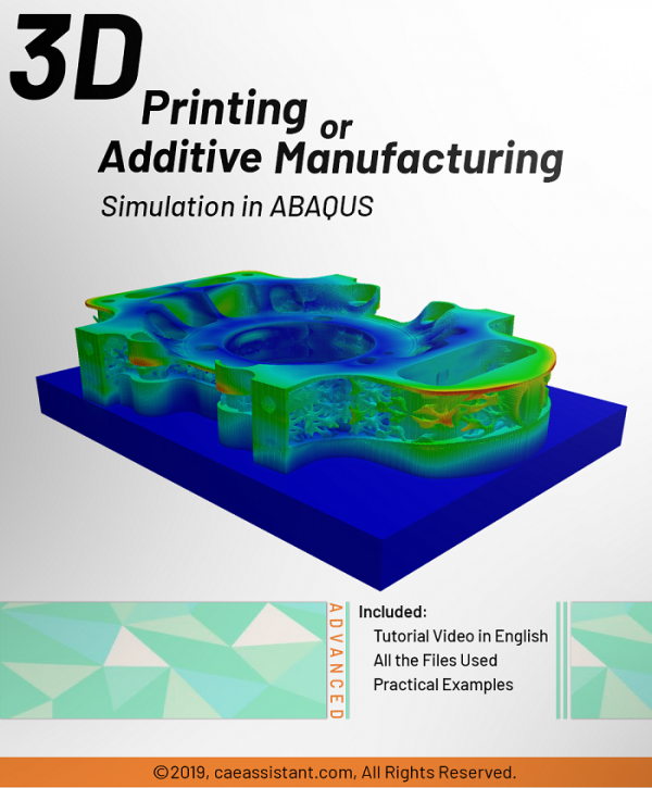
Additive Manufacturing or 3D Printing Python ABAQUS simulation
Why is Abaqus needed to model 3D printing? We do different simulations for the same reasons. examining the model’s deflection, the temperature and thermal conditions, the presence of any residual stress, etc. To prevent wasting money, it is also a good idea to check that the printer’s settings match the requirements of our model before printing. conditions such as temperature and material characteristics, etc.
This package will teach you to do this based on the use of subroutines and Python scripting and was done by a team with the goal of coding all the steps of 3D printing. 3D printing Python Abaqus simulation tutorial is one of the best training packages on the web about 3D printing FEM.
Using Scripting and Subroutines
This method involves three coding files: a Python script and two subroutines, USDFLD and DISP.
The Python program handles all necessary tasks, including creating material attributes, sections, and interactions in the Abaqus GUI. Users can execute the script, provide inputs, and wait for the simulation to complete. To build the model, users must use CAD software or Abaqus, layer it, and save individual layers as “igs” files. The directory path of these files should be an input when running the script.
The USDFLD subroutine calculates the elasticity properties of 3D printed objects, which are not constant and change throughout the process. According to the following references, the formulas used in this lesson to determine elasticity: “Rapid Prototyping & Manufacturing, Fundamentals of
Stereolithography“, “Curl Distortion Analysis During
Photopolymerisation of Stereolithography Using Dynamic Finite Element
Method“.
The equations and assumptions used to calculate the elasticity are explained in the “3D printing Python” tutorial video. Users can apply their own equations and assumptions if desired.
The DISP subroutine computes the temperature variations that occur during the process using calculations based on user presumptions. Users can also refer to other sources to apply their own calculations.
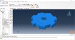
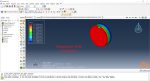
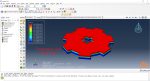
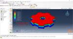
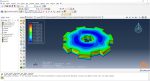
Each component utilizes a unique variation of the Python code. The first session involves replicating the 3D printing of a gear using a standardized, model-specific version of the Python programming language. To build the model, users only need to create one layer of the model in CAD software or Abaqus and save it as an “igs” file. When executing the code, users must enter the file’s directory path and a few other parameters before waiting for the task to complete.
Workshop 1: 3D printing Abaqus simulation of Gear with DISP, USDFLD and Python scripting (Same cross-section)
This workshop begins by explaining the model’s geometry. The difference between continuous and discontinuous layers is then discussed, which is an important issue when using the Python script for these types of examples. Material properties are explained in detail, along with their equations, and are defined using the USDFLD subroutine. Boundary conditions are then explained, followed by a discussion of temperature changes and their relationships, which are applied to the model using the DISP subroutine. Finally, the Python code and subroutines are described, and the simulation is performed. The results are then discussed.
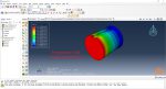
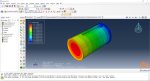
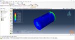
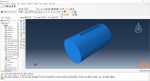
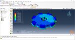
Workshop 2: 3D printing Abaqus simulation of shaft with DISP, USDFLD and Python scripting (non-uniform section)
Similar to the previous workshop, this workshop begins by explaining the model’s geometry. The model layering is then presented, and all other stages are the same as the previous workshop. The only differences are in the model’s geometry, Python code, and layers, as this model has a non-uniform cross-section.
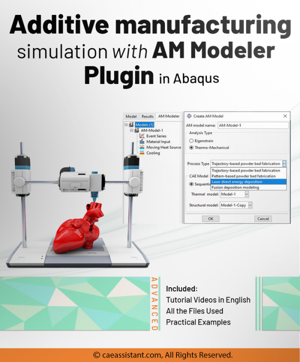
We can also use AM plug-in to simulate additive manufacturing or 3d printing FEM. If you are interested in having both methods or even want to learn more about 3D printing itself, I recommend going to this page: “Additive Manufacturing or 3D Printing simulation in ABAQUS”.

max.efa –
Thank you I understand all the topics due to this course, but the information could have been much better packaged and organized.
Experts Of CAE Assistant Group –
Thank you for your feedback. We appreciate your understanding of the topics covered in the course. We take your comment about the packaging and organization of the information seriously, and we apologize if it fell short of your expectations. We strive to continuously improve our course materials, and your input will help us in that process. If you have any specific suggestions or areas where you feel we can enhance the packaging and organization, we would be grateful to hear them. Thank you again for your feedback, and we’re glad that you found value in the course content.