Produced in Partnership Plan
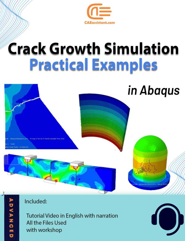
Abaqus Crack Growth | Practical Examples
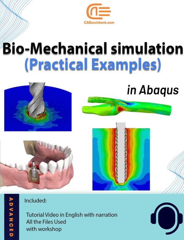
Bio-Mechanical Abaqus simulation | Practical Examples
This package offers multiple practical examples on biomechanical simulations using Abaqus, covering a range of applications from dental to orthopedic and cardiovascular analyses. The workshops delve into finite element method (FEM) simulations, exploring static loading on human teeth, crack growth in bones under bending, bone drilling, and the behavior of titanium foam implants. Each tutorial emphasizes the importance of precise modeling and meshing techniques, utilizing dynamic explicit procedures, Johnson-Cook material models, and various contact and boundary conditions to simulate realistic biomechanical behaviors. Additionally, the package includes fluid-structure interaction (FSI) simulations for blood flow within coronary vessels, addressing both Newtonian and non-Newtonian models, and demonstrates the integration of computational fluid dynamics (CFD) with structural analysis for enhanced accuracy. For more details on this topic, including explanatory videos covering the necessary formulation and theory in the form of a course, you can check out our full package on Abaqus Bio-mechanical simulation. The introduced package includes all the workshops within this package, along with several lessons in video format, to help you master the theory of biomedical simulation in Abaqus.
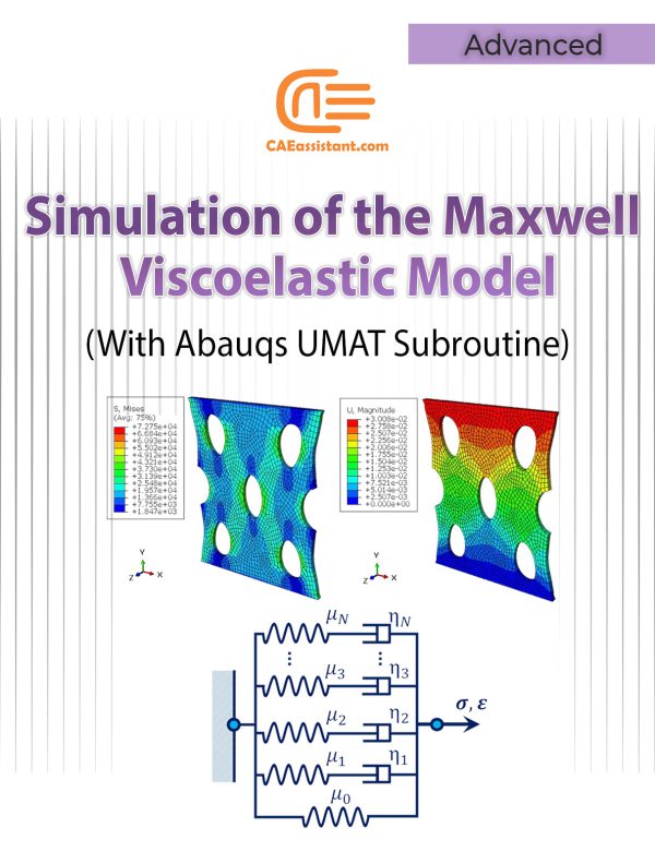
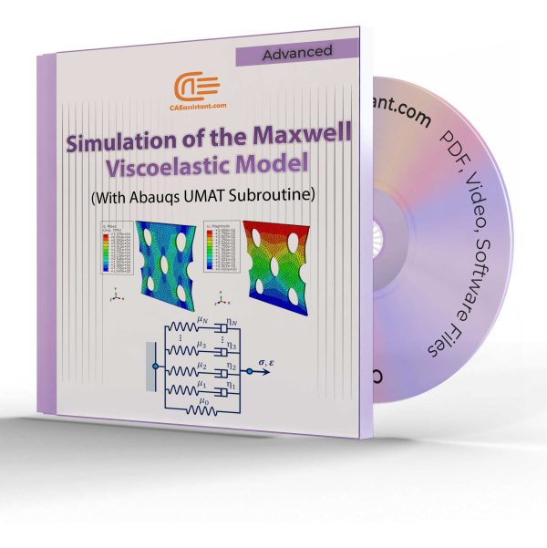
Simulation of the Generalized Maxwell Viscoelastic Model using UMAT Subroutine
This research presents a precise three-dimensional mechanical response of viscoelastic materials, such as polymers and elastomers, using the generalized rheological Maxwell viscoelastic model (considering the five Maxwell elements). That is to say, we implement the Maxwell model of viscoelasticity using the UMAT subroutine for the Abaqus standard solver. To clarify, using the concepts in this tutorial, you can implement the model for any N-Maxwell elements, using the viscoelastic Maxwell model.
The Maxwell viscoelastic model is appropriate for qualitative and conceptual analysis, but the single Maxwell element is not sufficient to describe the behavior of elastomers and polymers. For a more precise definition of these materials, the generalized Maxwell viscoelastic model is used. In the generalized Maxwell viscoelastic model, N piece of Maxwell elements and a single spring (the Hooke-element) are assembled in parallel. This tutorial, by customizing the UMAT subroutine to simulate flexible samples behavior, contributes to the advancement of viscoelastic materials design and analysis.
Essential Abaqus Training for Engineers: From Basics to Advanced Techniques
This beginner-friendly Abaqus course offers a complete guide to mastering finite element simulations through step-by-step tutorials and practical workshops. It covers essential topics such as Abaqus/CAE basics, finite element theory, composite material simulation, and thermal and impact analyses. Advanced sections delve into UMAT/VUMAT subroutines and Python scripting, equipping users with skills to automate workflows and solve complex engineering problems. Workshops include real-world examples like cantilever beams, forming processes, and fracture simulations. Perfect for engineering students and professionals, this course helps you build a solid foundation in Abaqus and expand your simulation capabilities.
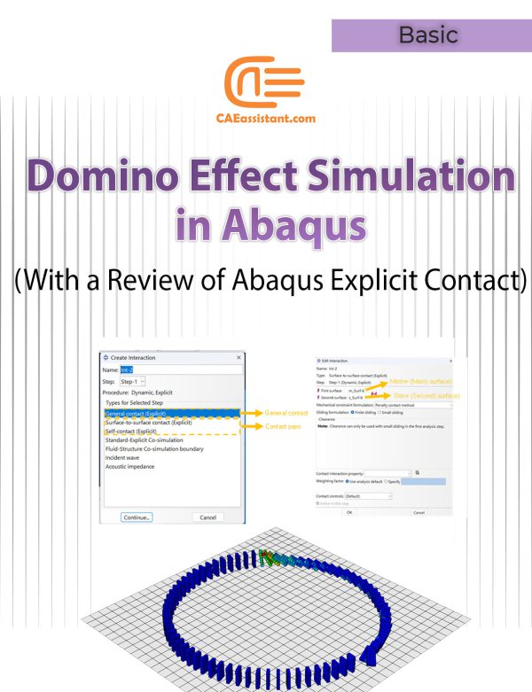
Domino Effect Simulation in Abaqus | With a Review of Contact Definition Methods in Abaqus Explicit
This project focuses on the domino effect simulation with Abaqus CAE, a widely recognized finite element program. The domino effect refers to a chain reaction where one event triggers a series of similar events. It often leads to larger and unpredictable consequences. The project highlights the challenges of defining contact between components in Abaqus, a crucial aspect of domino effect simulation. The provided video explains the step-by-step modeling process. However, since one of the key challenges in this topic is defining contact, we have also attached a separate PDF. It covers defining contact in Abaqus Explicit. It includes its formulations and methods. The PDF will provide you with a better understanding of the modeling process. You can also apply it to model other problems.
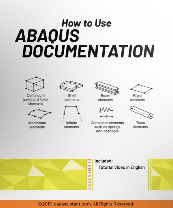
How to use ABAQUS Documentation
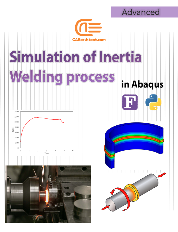
Simulation of Inertia Welding process in Abaqus | Fortran Subroutines and Python Scripts
This tutorial provides a comprehensive guide to simulating inertia friction welding process using Abaqus, a powerful Finite Element Analysis (FEA) tool. Inertia welding process, commonly used in aerospace, automotive, and manufacturing industries, is a solid-state process that joins metal parts using kinetic energy. The simulation focuses on modeling frictional heating, temperature distribution, and material behavior through integrated Fortran subroutines and Python scripts. These scripts automate tasks such as remeshing and model generation, enhancing efficiency. Key steps include defining axisymmetric models, applying material properties, and simulating thermal and mechanical interactions during the inertia welding process. This guide equips researchers and engineers with a robust methodology for inertia welding simulation, to optimize welding parameters and analyze weld quality.
Using Viscoelastic and Path-Dependent Models for Analyzing the Curing Process in Fiber-Reinforced Composites With Abaqus subroutines
Brittle Damage in Abaqus | Brittle Cracking Abaqus
Brittle materials, such as ceramics, glass, and concrete, break or fracture easily under stress without extensive deformation. Unlike ductile materials, brittle materials snap suddenly, lacking the flexibility to rearrange their atomic structure under strain. These materials have low tensile strength but strong compressive resistance, making them vulnerable to brittle cracking Abaqus simulations when stretched or pulled.
Understanding brittle material damage is crucial in safety-critical fields like civil engineering, aerospace, and manufacturing, where unexpected fractures can lead to catastrophic failures. Simulations help engineers predict when and how brittle materials may break, guiding safer design choices. Brittle cracking Abaqus can be modeled using various methods, including the Johnson-Holmquist (JH) model, XFEM, and energy-based approaches, each suited to different types of loading conditions.
For dynamic, high-strain applications like impacts, the JH model is effective, particularly in Abaqus/Explicit with specific damage parameters. For general crack modeling, XFEM is versatile, allowing cracks to form naturally without predefined paths. The energy-based method is useful for slow-loading scenarios, defining an energy threshold for fracture initiation. Each method requires careful input of material properties, mesh refinement, and load conditions to reveal potential failure points and improve material performance in real applications.
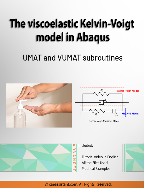
Abaqus Kelvin Voigt Model (Viscoelastic) Simulation Using UMAT and VUMAT Subroutines
This research presents a precise three-dimensional mechanical response of viscoelastic materials using Abaqus kelvin voigt viscoelastic model. We performed this kelvin voigt model Abaqus simulation using both UMAT and VUMAT subroutines for standard and explicit solvers.
The behavior of viscoelastic materials is a state between the behavior of a liquid and a solid. In other words, they behave both like liquids and solids. That is to say, there are many natural and synthetic materials that are classified as viscoelastic materials; From the biological structures of the body such as skin, cartilage and tissue to concrete, foams, rubbers, and synthetic polymers. Due to these unique properties, viscoelastic materials have many applications.
In this regard, the primary goals of this study include the development and implementation of an accurate three-dimensional Abaqus kelvin voigt viscoelastic model, and the integration of viscoelastic properties into the analysis, which can improve the prediction of viscoelastic materials response under different boundary and loading conditions.
This tutorial, by customizing the UMAT and VUMAT subroutines to simulate flexible samples behavior, contributes to the advancement of viscoelastic materials design and analysis.
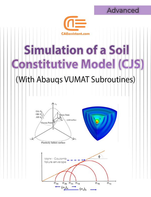
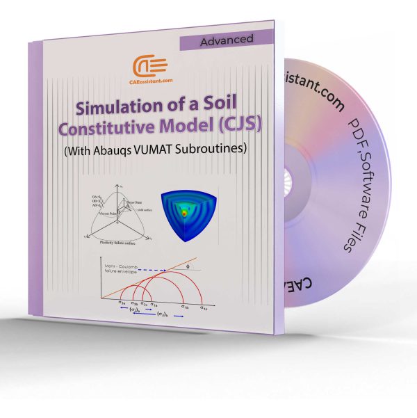
Implementation of Soil Constitutive Models in Abaqus | With a Special Focus on CJS Models
Constitutive model implemented in calculation code, play an important role in the material behaviors prediction. In the field of geotechnical engineering there are numerous soil constitutive models. By installing these models in a finite element code such as Abaqus, their development, efficiency and advancement can be increased. Also, more and more complex engineering problems can be solved by this method. But to do this, you need a proper understanding of the mathematical and programming basics of these models. This tutorial focuses on implementing advanced constitutive models in Abaqus, particularly for simulating soil behavior. Focusing on the CJS model, this tutorial tries to teach how to work and how to program these models in Abaqus code. It includes detailed explanations of VUMAT and UMAT subroutines and practical examples of implementing the CJS model.
Note: In this project, we have discussed the UMAT and VUMAT subroutines, their specifications, and features. You will become familiar with the implementation of both UMAT and VUMAT subroutines. However, the specific focus of this project, for which we have provided the necessary files and run the analysis, is on using the VUMAT model. If you need to use Abaqus for this project with the standard solver, you will need to write the UMAT subroutine yourself.
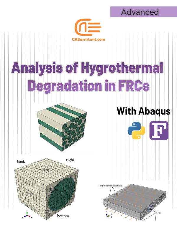
Hygrothermal effects on composite materials | Degradation in Fiber Reinforced Composites Abaqus Simulation: Python & Subroutines
In this tutorial, we explore the hygrothermal degradation composites using ABAQUS, a powerful tool for parallel finite element analysis. Industries like aerospace, marine, and automotive heavily rely on these composites due to their high strength-to-weight ratio and versatility. However, long-term exposure to moisture and temperature can degrade their mechanical properties, making an analysis of hygrothermal effects on composite materials essential for ensuring durability.
ABAQUS allows precise modeling of these environmental conditions through Python scripts and Fortran subroutines. This combination enables efficient simulations across multiple processors, offering insights into key elastic properties, such as Young’s modulus and shear modulus, under varying conditions. By leveraging the ABAQUS Python Scripting Micro Modeling (APSMM) algorithm and custom subroutines, engineers can predict the long-term performance of fiber-reinforced composites, optimizing design and enhancing material performance in critical sectors like aerospace and marine.
In the present Abaqus tutorial for parallel finite element analysis, we have presented the software skills that a person needs when he wants to perform a parallel finite element analysis such as a micro-macro scale analysis. The Abaqus tutorial for parallel finite element analysis covers all you need to write a python scripting code for noGUI environment and also Fortran code for the subroutine environment of Abaqus to execute a parallel finite element analysis via Abaqus software. You can download the syllabus of this package here.
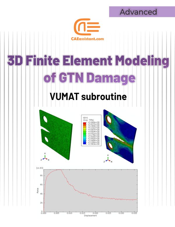
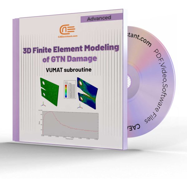
3D Simulation of Gurson-Tvergaard-Needleman (GTN) Damage Model
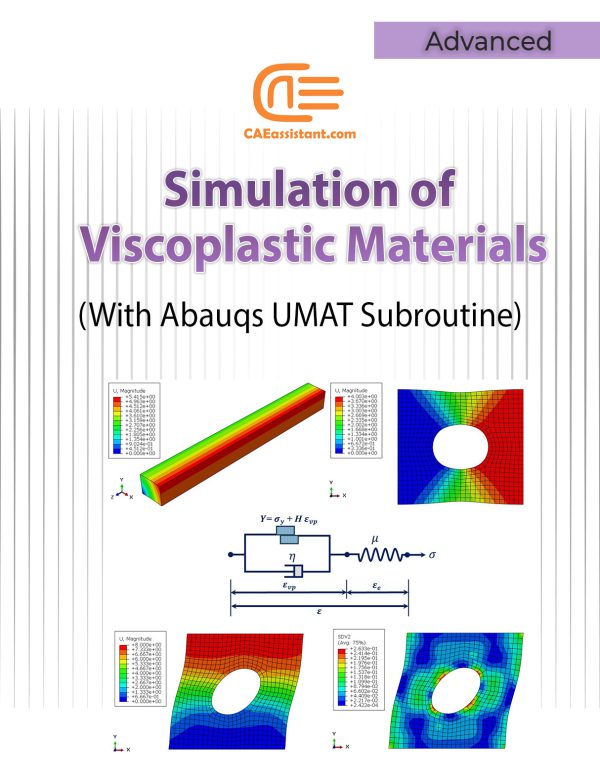
Viscoplasticity Abaqus Simulation Using UMAT Subroutine | Perzyna Viscoplastic Model
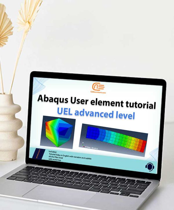
Abaqus User element tutorial | UEL advanced level
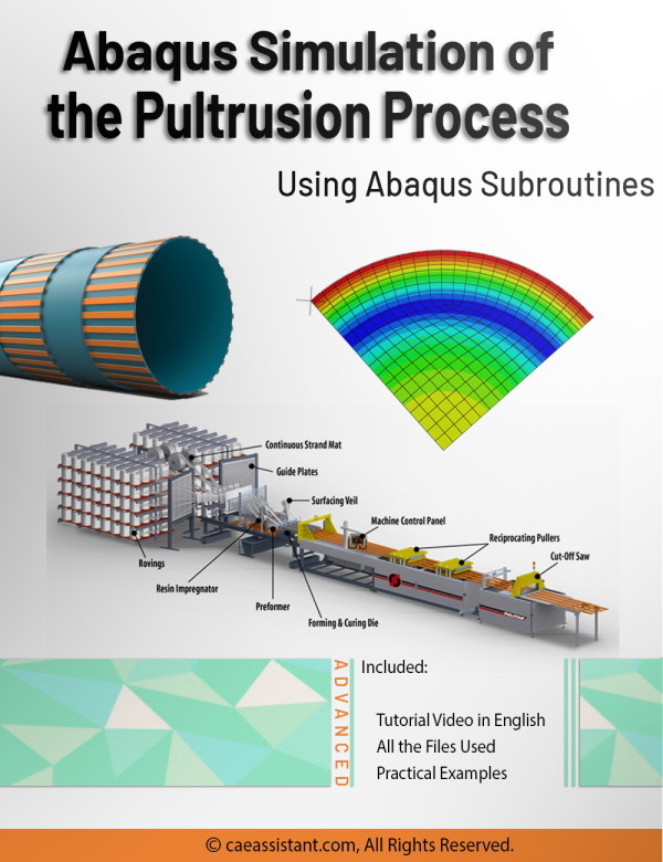
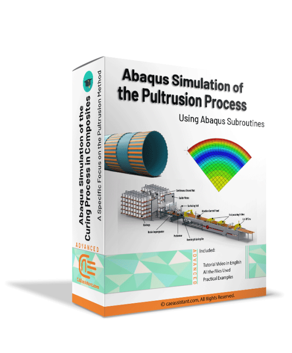
Abaqus Simulation of the Curing Process in Composites: A Specific Focus on the Pultrusion Method
Pultrusion is a crucial task for producing constant-profile composites by pulling fibers through a resin bath and heated die. Simulations play a vital role in optimizing parameters like pulling speed and die temperature to enhance product quality and efficiency. They predict material property changes and aid in process control, reducing reliance on extensive experimental trials. However, simulations face challenges such as accurately modeling complex material behaviors and requiring significant computational resources. These challenges underscore the need for precise simulation methods to improve Pultrusion processes. This study employs ABAQUS with user subroutines for detailed mechanical behavior simulations, including curing kinetics and resin properties. Key findings include insights into material property changes, and optimization strategies for enhancing manufacturing efficiency and product quality. This research provides practical knowledge for implementing findings in real-world applications, advancing composite material production.
Notice that, pultrusion is a composite curing method, which may share some overlapping features with our Intermediate and Advanced curing packages. However, what sets pultrusion apart is that the composite passes over a heated die during the process. In this project, the die has also been modeled, with environmental heat applied to it using convection and a film subroutine. The heat is subsequently transferred to the sample through contact with the die. Afterward the die is removed. All these procedure is modeled in this project, with Abaqus CAE step-by-step. In contrast, in our Intermediate and Advanced packages for the oven curing of prepregs, no die has been modeled. The heat is applied without convection and, for simplicity, the heat is treated as a first-type boundary condition, which introduces some errors.
Note: The files and video which explains how to use the code are available. The PDF file will be available two weeks after purchase.Elastomeric Foam Simulation Using Abaqus Subroutines
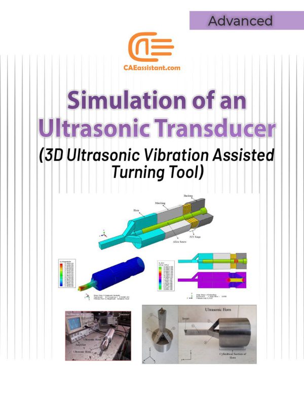
Simulation of an Ultrasonic Transducer (3D Ultrasonic Vibration Assisted Turning Tool)
Since the invention of ultrasonic vibration assisted turning, this process has been widely considered and investigated. The reason for this consideration is the unique features of this process which include reducing machining forces, reducing wear and friction, increasing the tool life, creating periodic cutting conditions, increasing the machinability of difficult-to-cut material, increasing the surface quality, creating a hierarchical structure (micro-nano textures) on the surface and so on. Different methods have hitherto been used to apply ultrasonic vibration to the tip of the tool during the turning process. In this research, a unique horn has been designed and constructed to convert linear vibrations of piezoelectrics to three-dimensional vibrations (longitudinal vibrations along the z-axis, bending vibrations around the x-axis, and bending vibrations around the y-axis). The advantage of this ultrasonic machining tool compared with other similar tools is that in most other tools it is only possible to apply one-dimensional (linear) and two-dimensional (elliptical) vibrations, while this tool can create three-dimensional vibrations. Additionally, since the nature of the designed horn can lead to the creation of three-dimensional vibrations, there is no need for piezoelectric half-rings (which are stimulated by a 180-phase difference) to create bending vibrations around the x and y axes. Reduction of costs as well as the simplicity of applying three-dimensional vibrations in this new method can play an important role in industrializing the process of three-dimensional ultrasonic vibration assisted turning.
In this example, how to model all the components of an ultrasonic transducer and its modal and harmonic analysis are taught in full detail.
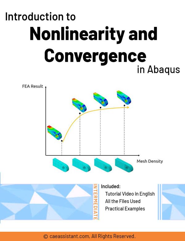
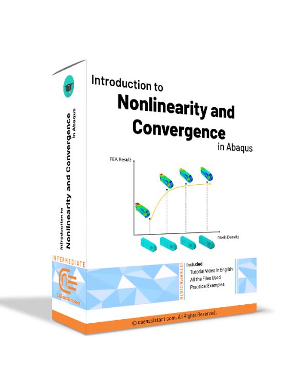
Abaqus convergence tutorial | Introduction to Nonlinearity and Convergence in ABAQUS
This package introduces nonlinear problems and convergence issues in Abaqus. Solution convergence in Abaqus refers to the process of refining the numerical solution until it reaches a stable and accurate state. Convergence is of great importance especially when your problem is nonlinear; So, the analyst must know the different sources of nonlinearity and then can decide how to handle the nonlinearity to make solution convergence. Sometimes the linear approximation can be useful, otherwise implementing the different numerical techniques may lead to convergence.
Through this tutorial, different nonlinearity sources are introduced and the difference between linear and nonlinear problems is discussed. With this knowledge, you can decide whether you can use linear approximation for your nonlinear problem or not. Moreover, you will understand the different numerical techniques which are used to solve nonlinear problems such as Newton-Raphson.
All of the theories in this package are implemented in two practical workshops. These workshops include modeling nonlinear behavior in Abaqus and its convergence study and checking different numerical techniques convergence behavior using both as-built material in Abaqus/CAE and UMAT subroutine.
