Simulation of car industrial parts in Abaqus
Car industrial parts are complex and critical components that play a vital role in the operation of a car. Two such parts are the exhaust manifold and the internal combustion engine (IC engine). The exhaust manifold is responsible for collecting and directing hot exhaust gases from the engine’s cylinders into the exhaust system. It is typically made of cast iron or stainless steel and must be able to withstand high temperatures and pressures. The IC engine is responsible for converting fuel into mechanical energy to power the car. It does this by burning fuel in a series of controlled explosions within the engine cylinder.
Simulation of car industrial parts in Abaqus
Using Abaqus, simulations can be performed to assess the performance of critical car industrial parts such as the exhaust manifold and internal combustion engine (IC engine). The simulations consider the materials used, high temperatures, and pressures that these parts must withstand, and the stresses that result from constant combustion. Abaqus provides a range of material models and numerical techniques to accurately simulate the behavior of these parts under various loading conditions. Through a combination of thermal and stress analyses, Abaqus can identify areas of potential failure and provide insight into the design and maintenance of these parts to ensure proper functioning and longevity in a car. The two workshops below help you to simulate and analyze car industrial parts such as an exhaust manifold.
Workshop 1 : Heat transfer analysis in an exhaust manifold
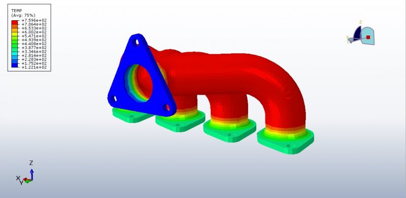
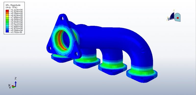
Three processes control heat transfer in engine exhaust manifolds: conduction through the metal, convection from the hot exhaust gases, and radiative exchange between various metal surface areas. This example shows how to calculate a manifold’s equilibrium thermal state under these effects. The process consists of a single heat transfer step in which the conditions for thermal loading are scaled up from zero. The temperatures at the cylinder head and outlet are fixed, therefore the boundary constraints on the manifold flanges are a simplification of those encountered under operational conditions. The interior surfaces of the manifold tubes experience convection as a result of heat transfer from the hot exhaust. The cavity radiation approach, with and without cavity parallel decomposition enabled, and using average-temperature radiation conditions are all used to describe the radiation between the internal surfaces of the tubes. Gray iron was used to cast the manifold. When employing the cavity radiation technique, the peak temperature in the field is higher. High-temperature zones radiate more heat, which is absorbed by the cooler parts, resulting in a smoothing of the temperature field in the equilibrium solution. This smoothing effect in the cavity radiation method is constrained and influenced by geometric view factors: the size and orientation of the surface facets influence the amount of radiation exchange that can take place. When employing radiation conditions with average temperature, this is not the case. Only a facet’s temperature and the average cavity temperature are taken into account when determining whether it will absorb or emit radiation; view factors’ localizing effects are not taken into account. Since the radiation model utilized had a stronger smoothing impact, the average method findings show lower peak values.
Workshop 2: Structural and thermal analysis of exhaust manifold
This tutorial has looked at the Thermal and Structural Analysis of the Exhaust Manifold in Abaqus. Because the geometry of the manifold is intricate, SolidWorks is used to import it into Abaqus.
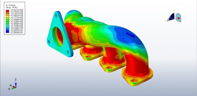
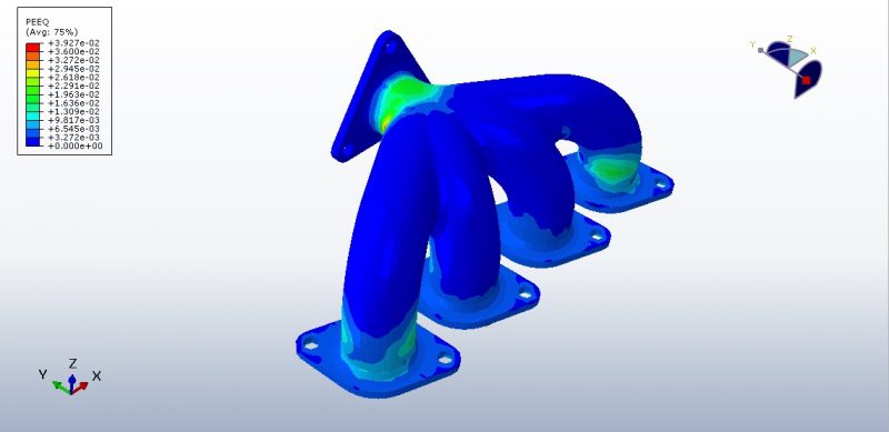
The exhaust manifold, which is mounted on the cylinder of an internal combustion engine, is a crucial part of an engine in the world of automobiles. For a smooth exhaust, the gases entering from the cylinder head at various exhaust strokes are collected with the least amount of backpressure. Gases from other strokes must smoothly discharge after those arriving from one cylinder at a given stroke. Gases were delivered into a common pipe from various pipes before going into the muffler. The design of the manifold and effective emission of combustion products are crucial factors that determine the performance of an internal combustion engine. When the engine cylinder expels exhaust gases, they have a high temperature and pressure, ranging from 800°C and 100kPa to 500kPa, respectively. The surface of the manifold experiences a lower temperature, typically between 250°C and 300°C. Due to these temperature gradients, the manifold exerts a thermal load on the material, causing it to move from its mounted position with the cylinder head. This thermal load, when combined with the structural load from bolt pretension, results in stresses on both the manifold and bolt materials. It is important to ensure that these stresses are within safe limits for proper design. Therefore, a thermo-mechanical analysis should be performed during the initial stages of design to assess the potential stresses and ensure safe operation. To ensure proper performance of the manifold, it is important to select material data that are suitable for the expected temperature range. The simulation process for assessing the manifold has two main sections: thermal analysis and stress analysis. During the thermal analysis, Abaqus calculates the temperature using a thermal step, and then applies that temperature to consider thermal stress during a subsequent static step. To ensure accuracy, the simulation assigns convection and radiation properties to the internal surfaces and carefully considers the appropriate boundary conditions for both sections. A fine mesh is critical for obtaining accurate results. Once the simulation is complete, the results of both the thermal and stress analyses are available for review.
It would be useful to see Abaqus Documentation to understand how it would be hard to start an Abaqus simulation without any Abaqus tutorial.


Brittany –
I would like to express my appreciation to CAE Assistant for providing this instructional package for simulating industrial car parts in Abaqus. These tutorials and examples are extremely valuable and enable users to improve the performance of thermal and structural components in automotive applications using various techniques and models in Abaqus.
Experts Of CAE Assistant Group –
Thanks for your kind review!