Introduction to Low-velocity impact analysis
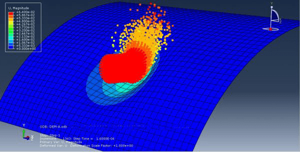
The differentiation between low-velocity impact and high-velocity impact analyses is typically based on the speed or velocity at which the impact occurs. While there isn’t a universally defined threshold, the distinction is generally made based on the relative velocities involved and the resulting effects on the materials and structures. Low velocity impact typically refer to relatively slower and less energetic events. These impacts occur at speeds where the kinetic energy involved is relatively lower. Examples include minor collisions, accidental drops, or low-speed vehicle impacts. The velocities involved in low-velocity impacts are typically below a certain threshold, which can vary depending on the context and industry. However, it is generally considered to be within the range of a few meters per second (m/s) to several tens of meters per second.
It’s important to note that the specific threshold for differentiating low and high-velocity impacts can vary depending on the industry, specific application, or engineering standards. The context and purpose of the analysis play a significant role in determining whether an impact is considered low or high velocity. Engineers and researchers in each field establish criteria and thresholds based on their expertise and the specific requirements of the problem at hand.
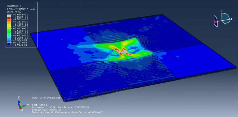
Workshop 1 : Low velocity impact simulation to the hybrid core sandwich structure
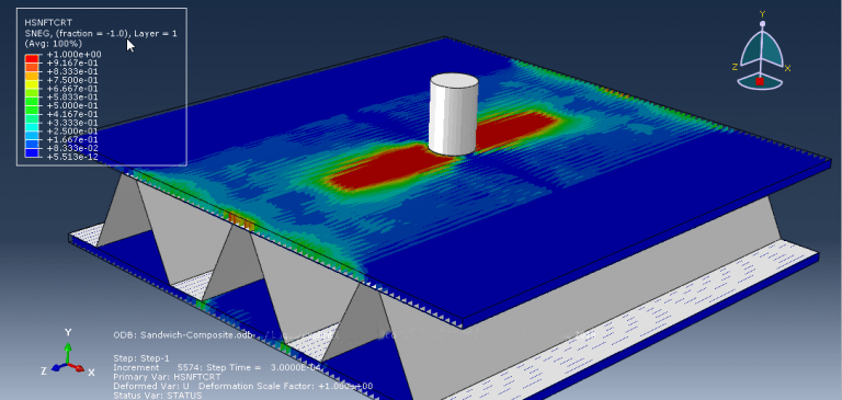
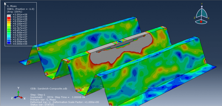
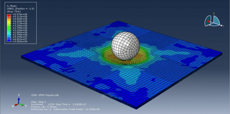
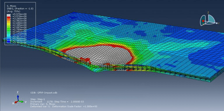
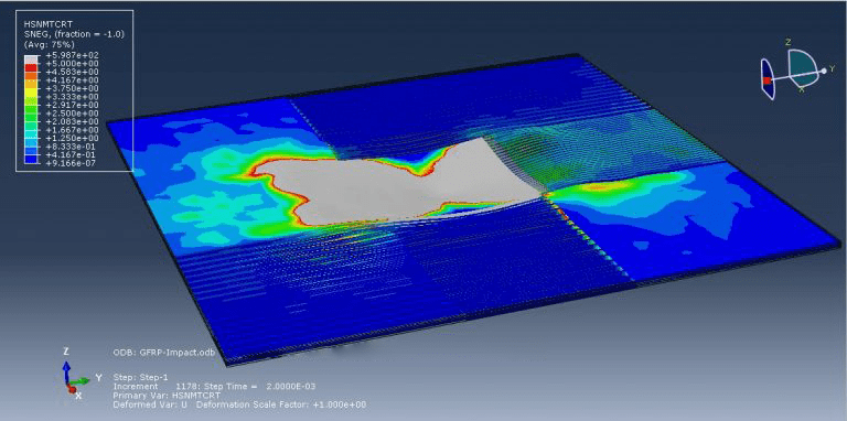
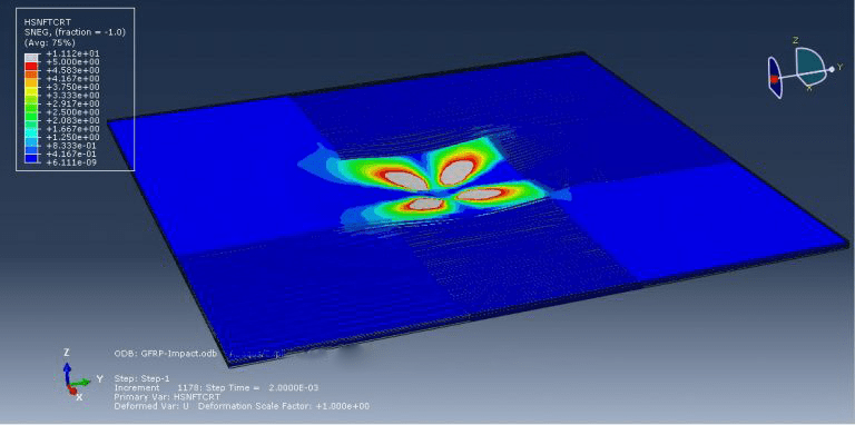
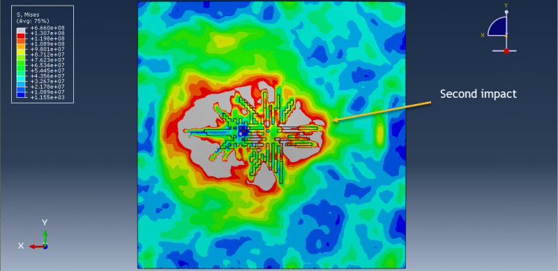
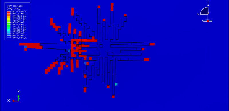
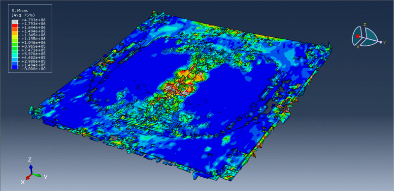
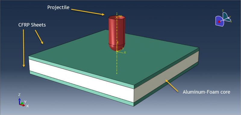
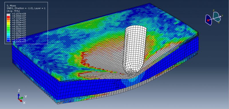
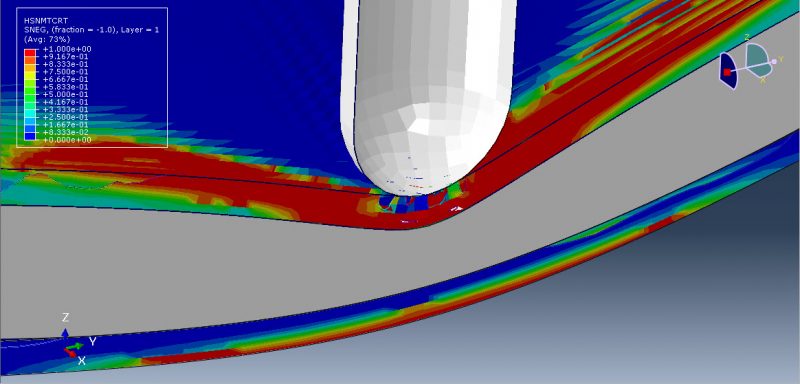
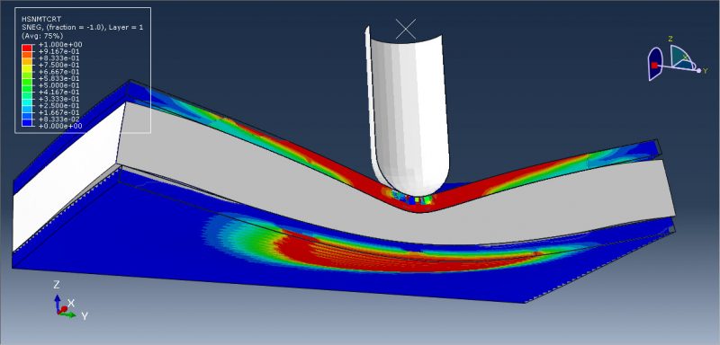
Core sandwich structures are produced using face sheets made of Epoxy-Glass fiber reinforced with aluminum alloy cores. This design concept allows sandwich structures to optimize their specific bending stiffness and strength while enhancing their ability to absorb energy. To simulate the behavior of composites during impact, Hashin failure criteria has been employed. The explicit procedure is deemed suitable for this analysis, particularly when the sandwich panel experiences collapse during the impact.
Workshop 2: Low velocity impact simulation of reinforced RC slab with CFRP strips
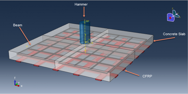
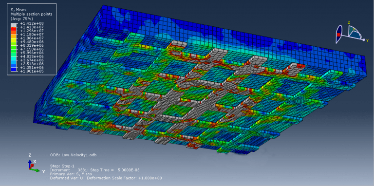
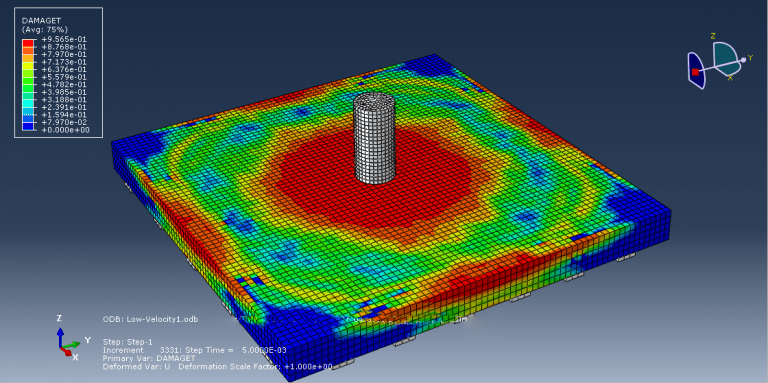
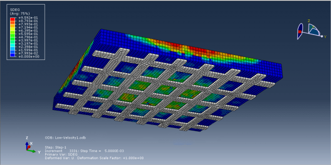
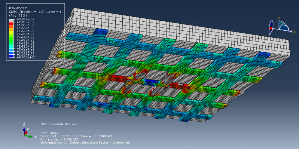
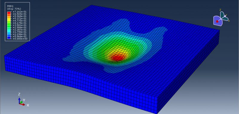
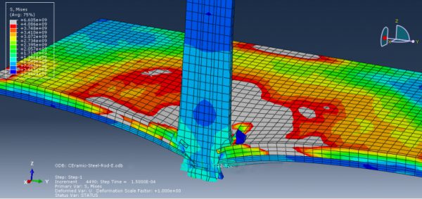
This tutorial explores the behavior of reinforced concrete (RC) slabs strengthened with CFRP (carbon fiber-reinforced polymer) strips under low velocity impact using Abaqus software. Reinforced concrete slabs are commonly used in construction projects and are designed to withstand vertical static and dynamic loads. However, the design process often overlooks the effects of impulsive dynamic loads such as impact. The response of RC slabs to impact loading is still not fully understood, but research in this field continues due to its relevance in various applications. These include reinforced concrete structures designed to withstand accidental scenarios like rock falls, vehicle or ship collisions with buildings, bridges, or offshore facilities, as well as structures used in high-threat or high-hazard environments like military fortifications or nuclear facilities. Consequently, significant efforts have been made to develop design procedures that enhance the impact resistance and performance of reinforced concrete structures.
In this study, the concrete slab is represented as a three-dimensional component using the CDP (Concrete Damage Plasticity) material model. The CFRP strips, on the other hand, are modeled as three-dimensional shell components with elastic properties, coupled with Hashin’s damage criteria. The reinforcing bars are modeled as wire components using an elastic-plastic material model.
The simulation utilized a dynamic explicit step with surface-to-surface contact. The contact between the concrete and CFRP is treated as perfect contact, and an embedded region constraint is applied to the reinforcing bars within the concrete. Fixed boundary conditions are applied to the slab, and an initial velocity is assigned to the rigid body. The mesh used in the simulation has a positive impact on the propagation of tensile and compressive damage, as well as other obtained results.
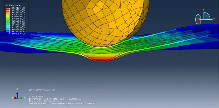
Workshop 3 : Low-velocity impact simulation and damage assessment of glass fiber aluminum laminates
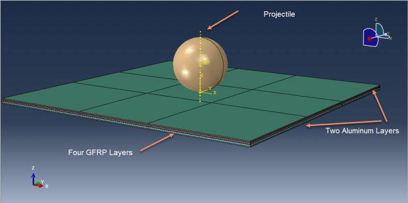
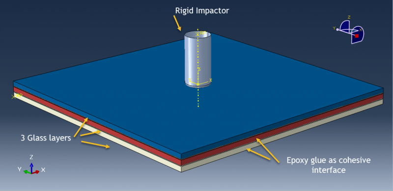
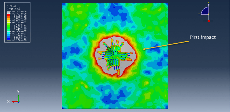
This tutorial examines the simulation of the response to low-velocity impacts and the damage mechanism of glass fiber aluminum laminates (GLARE) in Abaqus software. GLARE is a type of material commonly used in aircraft structures and is often exposed to low velocity impact events. The objective of this study is to analyze the dynamic response and damage mechanism of GLARE when subjected to single and repeated low-velocity impacts. The simulation involves the use of two aluminum plates at the top and bottom, with four glass fiber plates in the middle.
To predict the deformation and damage caused by a rigid projectile on aluminum plates, the Johnson-Cook plasticity and damage model was employed. As for the glass fiber, it was represented using engineering constant elasticity and Hashin’s damage criterion specifically for fibers. The dynamic explicit procedure was deemed suitable for this type of analysis. In the contact area, cohesive behavior was implemented to account for stiffness, damage, and tangential behavior. If the impact energy exceeds the predefined value in the cohesive contact, delamination occurs between the surfaces. It is important to have a fine mesh in the impact zone. Following the simulation, outputs such as stress, strain, damage, and other relevant data can be obtained.
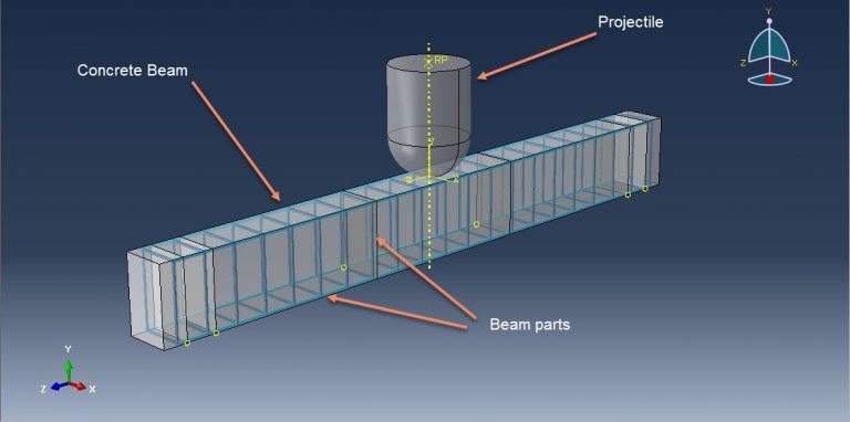
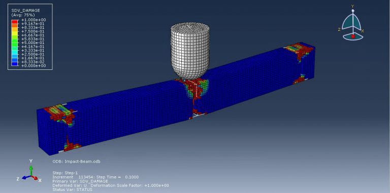
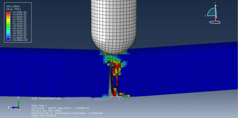
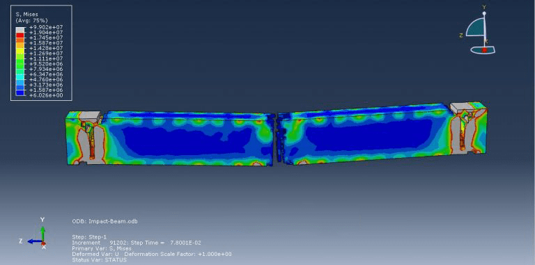
Workshop 4 : Damage investigation caused by low-velocity impact on reinforced concrete beam
This tutorial examines the investigation of damage caused by low-velocity impact on a reinforced concrete beam in Abaqus. Reinforced concrete structures have been widely utilized for many years, but our understanding of their behavior when subjected to impact loads is still limited. Existing design codes employ an equivalent static approach to offer general design principles for structures under impact loads. The impact force and displacement of reinforced concrete beams can be estimated using common spring-mass models, such as single degree of freedom (SDOF) or two degrees of freedom (2DOF). In this study, the concrete beam is represented as a three-dimensional component, while the steel beams are represented as wire elements, and the projectile is modeled as a rigid body.
The steel material is represented in the model as an elastic-plastic material with ductile damage properties. When it comes to the concrete material, its modeling is crucial, but the available material models in Abaqus’ library are not suitable for accurately predicting damage and failure. Therefore, in this simulation, the Johnson-Holmquist material model is employed. For this type of analysis, the dynamic explicit procedure is considered appropriate.
The beams are implemented as embedded regions within the concrete host, and surface-to-surface contact with penalty contact behavior is utilized to define contact interactions. An initial velocity is assigned to the projectile to initiate the impact. It’s worth noting that the quality of the mesh used in the simulation significantly affects the results.
Following the simulation, valuable information such as damage, stress, strain, and load diagrams can be obtained.












Gang –
The 6 workshops are awesome!
Experts Of CAE Assistant Group –
Thanks for review!
Ottilie –
Has this tutorial package provided a detailed explanation of low-velocity impact simulation in Abaqus? I would like to learn more about the methods and practical examples in this field.
Experts Of CAE Assistant Group –
Sure. it includes step-by-step video training along with related files