Workshop 1: Simulating the long-term load capacity of a pipe pile using Abaqus
In this tutorial, the simulation and calculation of the long-term load capacity of a pipe pile using Abaqus are explored. The pile in this example is cylindrical and subjected only to axial loading, allowing for the use of an axisymmetric finite element mesh for both the pile and surrounding soil. This axisymmetric simplification is not applicable for piles subjected to horizontal loads, which must be modeled as three-dimensional structures. It is also important that the finite element mesh of a soil–pile system incorporates interface elements to simulate the frictional interaction between the pile surface and the soil. While simulating the pile–soil interaction during pile driving is challenging, it is not attempted in this study. Instead, the pile is assumed to be in perfect contact with the soil prior to loading, with any excess pore water pressures from pile driving assumed to have dissipated before applying the loads.
The clay layer is modeled using four-node axisymmetric quadrilateral elements, with bilinear displacement and bilinear pore water pressure. The pile itself uses four-node bilinear axisymmetric quadrilateral reduced-integration elements, without considering pore water pressure. The clay layer’s base is fixed in both horizontal and vertical directions, while the left vertical boundary is treated as a symmetry line. The right vertical boundary is fixed horizontally but free vertically. The mesh is finer around the pile due to stress concentration in this area, though no mesh convergence studies have been conducted. The clay layer dimensions are chosen to minimize boundary effects on pile behavior.
In this example, the loading rate is very slow, and pore pressures are assumed to be zero throughout the analysis, resulting in a fully drained condition. Stress and strain during pile penetration are measured, and a force-displacement diagram is obtained.
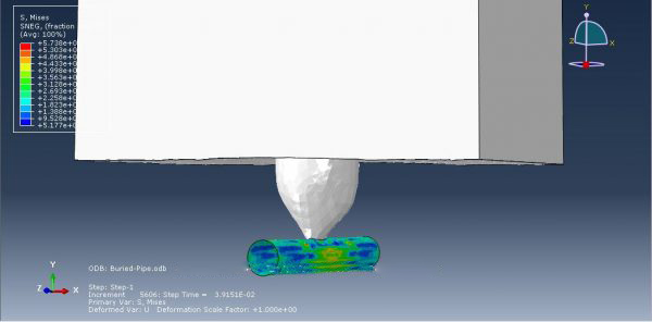
Workshop 2: Simulating a CEL explosion in Abaqus near a solid steel pipe buried in the soil
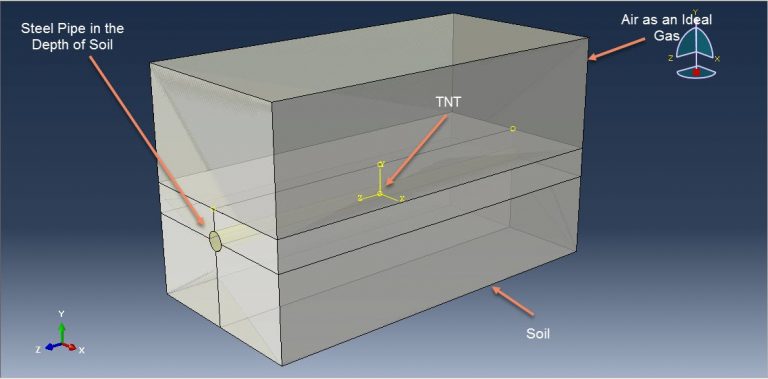
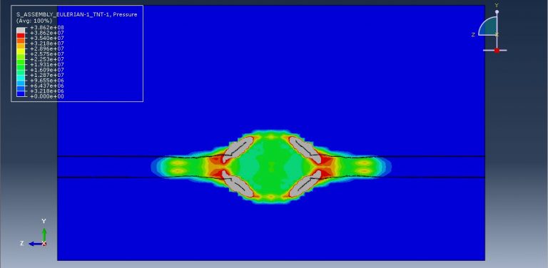
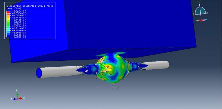
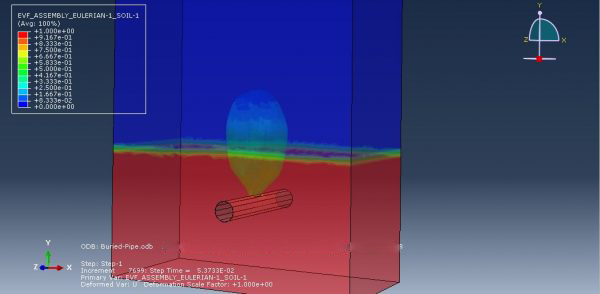
This tutorial focuses on the simulation of a CEL explosion near a buried solid steel pipe using Abaqus. The Eulerian domain is modeled as a three-dimensional part, while the air, soil, and TNT are represented as three-dimensional solid parts. The steel pipe is also modeled as a three-dimensional solid structure.
Buried pipelines, commonly used for transporting water, gas, and oil, are critical lifeline components. Pressurized gas pipelines, in particular, are vulnerable to accidental explosions in industries such as process plants, explosives factories, open-pit mines, quarries, and even intentional attacks like terrorism, which has increased in recent years. These threats have highlighted the importance of analyzing the effects of blast loads on buried structures and designing them to withstand destructive dynamic loads.
In this simulation, the behavior of the steel pipe under extreme loading is modeled using elastic-plastic material properties. The Johnson-Cook plasticity model, along with Johnson-Cook damage criteria, is employed to simulate steel pipe failure during detonation. The air is modeled using the ideal gas equation of state with dynamic viscosity, while the soil behavior is defined with elastic properties and Mohr-Coulomb plasticity. For the TNT explosion, the Jones-Wilkens-Lee (JWL) equation of state is used to simulate the pressure from the release of chemical energy, implemented as a programmed burn where initiation is based on the detonation wave speed and distance from detonation points, rather than material shock.
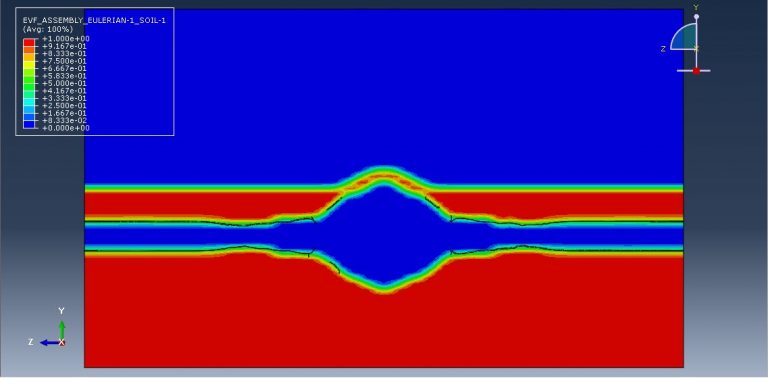
A dynamic explicit step is suitable for this type of analysis, and general contact capabilities with contact properties are applied. Non-reflecting boundaries are assigned to the outer surfaces of the Eulerian domain, while fixed boundary conditions are applied to both ends of the pipe. The volume fraction method is used to define material locations within the Eulerian domain, and a finer mesh is recommended for more accurate results.
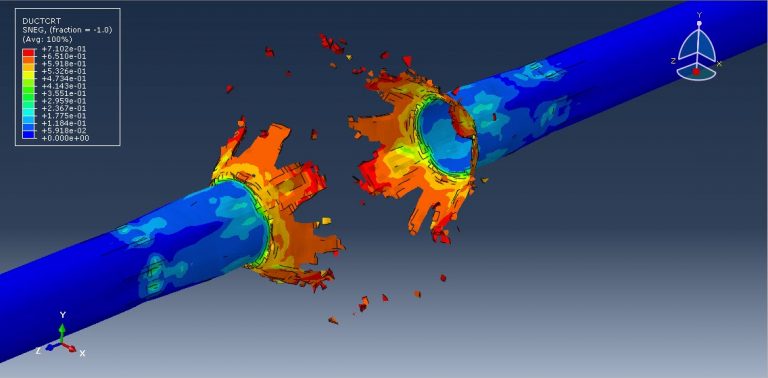
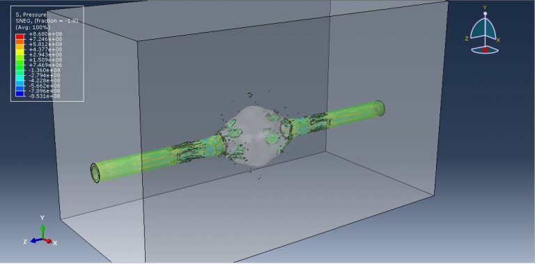
Workshop 3: CEL explosion simulation inside a steel pipe buried in the soil
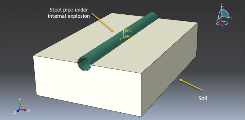
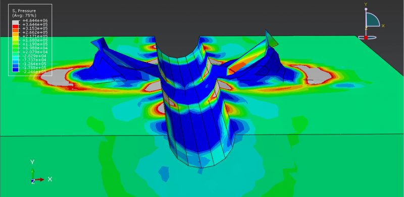
This tutorial examines the simulation of a CEL explosion inside a steel pipe embedded in soil using Abaqus. The steel pipe is modeled as a three-dimensional shell component, while the TNT, soil, and air are represented as three-dimensional solid components. Additionally, the Eulerian domain is modeled as a three-dimensional Eulerian component.
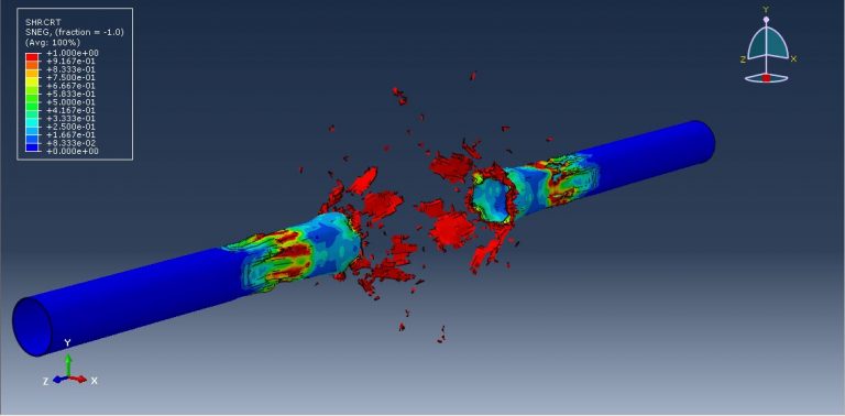
The steel pipe is defined using elastic-plastic material properties and includes ductile and shear damage criteria to predict potential failure areas after detonation. The TNT behavior is modeled using the Jones-Wilkens-Lee (JWL) equation of state, which converts the chemical energy from the explosion into mechanical pressure. The air is represented by the ideal gas equation with viscosity, and the soil is modeled using Mohr-Coulomb plasticity to capture its behavior.
A dynamic explicit step is selected for this analysis. General contact interactions are applied with suitable contact properties. Fixed boundary conditions are imposed at both ends of the pipe, while the Eulerian boundaries are applied to the Eulerian domain. The volume fraction method is used to calculate the volume distribution of TNT, soil, and air. A fine mesh is crucial for achieving accurate and reliable simulation results.
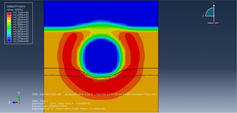
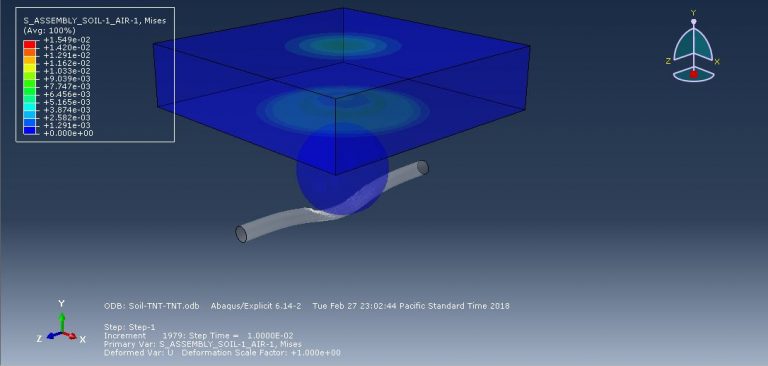
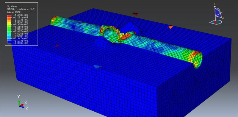
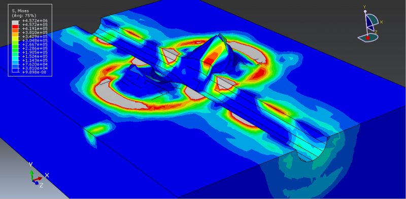
Post-simulation, results such as damage, stress, strain, and potential failure areas are analyzed. The TNT detonation generates a pressure wave that causes significant damage to the pipe, penetrating through the pipe and affecting the surrounding soil and air.
Workshop 4: Simulating a subsurface explosion on buried steel pipelines using the Eulerian-Lagrangian method
Buried pipelines are critical for distributing essential resources like water, gas, and oil. However, pressurized underground gas pipelines face significant risks from accidental explosions in industries such as explosives factories, quarries, public works, and open-pit mines, as well as intentional explosions near pipelines. Recently, there has been an increase in terrorist attacks and sabotage targeting oil and gas transmission pipelines, leading to multiple explosions along their routes.
This tutorial presents a coupled 3D finite element model using a combined Eulerian-Lagrangian approach to simulate explosions in Abaqus CEL. The simplified Johnson-Cook material model is used to represent the pipe’s material behavior, while the Jones-Wilkens-Lee (JWL) equation of state models the explosive charge detonation, and the ideal gas equation of state models the behavior of air. The soil mass is simulated using Coulomb-Mohr plasticity to capture its mechanical response under blast loads.



Nkurunziza –
I used this package for a project requiring advanced soil and pipeline modeling. What impressed me was the logical, step-by-step explanation of the workshops. I successfully applied the Mohr-Coulomb plasticity model to analyze soil behavior under critical conditions. Additionally, the use of the JWL equation for explosives was another strength of this package.
Mugisha –
As a structural engineer, this package helped me conduct precise analyses of pipeline behavior under dynamic and static loads. The simulations of explosions near pipelines and the explanations about selecting suitable models for different materials added immense value to the package.
Hategekimana –
Since purchasing this package, I have significantly improved my knowledge and skills in pipe-soil interaction analysis. The examples in the package were designed not only to clarify concepts but also to have practical applications. The simulations related to mechanical damage to pipelines were particularly useful.
Kwizera –
This tutorial package was highly beneficial for me as someone working in the oil and gas industry. I was able to analyze the impact of various loadings on underground pipelines and practically experience insights I had only seen in articles before. Additionally, the tips on Abaqus model settings helped me avoid common mistakes.