


What are Ultra-High-Performance Fiber Reinforced Concrete (UHPFRC) structures?
Ultra-High-Performance Fiber Reinforced Concrete (UHPFRC) structures are a specialized type of concrete that incorporates a high volume of steel or synthetic fibers to enhance its mechanical properties and performance. UHPFRC is known for its exceptional strength, durability, and resistance to cracking and deformation. The unique composition of UHPFRC includes a high cementitious content, a low water-to-cement ratio, fine aggregate, and a high concentration of steel or synthetic fibers such as steel, polyethylene, or carbon fibers. These fibers provide reinforcement to the concrete matrix, improving its tensile strength and ductility.
UHPFRC structures offer several advantages over traditional concrete structures. They have significantly higher compressive strength, allowing for the construction of slimmer and lighter elements. UHPFRC also exhibits excellent resistance to impact, blast loads, and cyclic loading, making it suitable for structures exposed to severe conditions. The reduced permeability of UHPFRC minimizes the ingress of moisture, chemicals, and aggressive agents, enhancing its durability and longevity.
UHPFRC structures are utilized in a wide range of applications, including bridge construction, architectural facades, high-rise buildings, tunnels, and marine structures. They are particularly beneficial in projects that require high-strength, durability, and superior performance under challenging conditions.
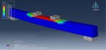
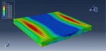
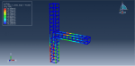
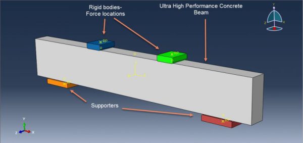
Workshop 1: Four points bending simulation of Ultra High Performance Fiber Reinforced Concrete (UHPFRC) beam
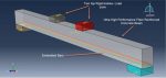
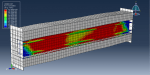
This tutorial focuses on investigating the behavior of an ultra-high-performance fiber-reinforced concrete beam under four-point bending using Abaqus. In recent decades, significant research and development efforts have been dedicated to enhancing the properties of concrete, resulting in the emergence of ultra-high-performance concrete (UHPC). UHPC exhibits remarkable characteristics such as high compressive strength, good tensile strength, enhanced toughness, and durability. However, one limitation of UHPC is its inherent brittleness. To address this, fibers are commonly incorporated into UHPC, resulting in ultra-high-performance fiber-reinforced concrete (UHPFRC). The addition of fibers significantly improves the ductility, fracture toughness, and energy absorption capacity of the concrete.
In the simulation, the concrete beam is represented as a three-dimensional solid component, while the steel bar is modeled as a three-dimensional wire component. By employing Abaqus, this study aims to analyze the response of the UHPFRC beam under four-point bending, providing insights into its structural behavior, load-bearing capacity, and deformation characteristics.
The bar is made of steel and is modeled using an elastic-plastic material. The ultra-high-performance fiber-reinforced concrete beam is represented using the Concrete Damaged Plasticity model, which defines its compression and tensile behavior. The parameters and properties for the materials are obtained from a reference paper.
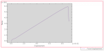
To calculate failure based on the force-displacement diagram, a general static step is used, with some adjustments made to the convergence model. The simulation incorporates a surface-to-surface contact algorithm between the rigid bodies and the concrete beam. The bar is embedded within the concrete beam as the host material. The two bottom rigid bodies are assigned fixed boundary conditions, while the two top rigid bodies have a specified displacement.
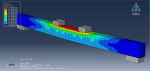
For accurate results, a fine mesh is required to ensure proper representation of the geometry and behavior of the materials in the simulation.
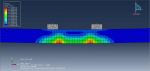
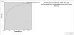
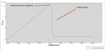
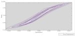
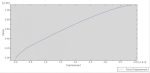
Once the simulation is complete, various results such as stress, strain, and displacement can be obtained. The force-displacement diagram provides an accurate visualization of the failure zone, aiding in the analysis and understanding of the structural behavior of the ultra-high-performance fiber-reinforced concrete beam.
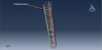
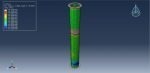
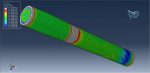
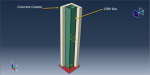
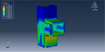
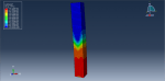
Workshop 2: Ultra High Performance Fiber Reinforced Concrete Column axial compression simulation
This tutorial focuses on examining the behavior of an Ultra-High-Performance Fiber Reinforced Concrete (UHPFRC) column under axial compression using Abaqus. The UHPFRC column is represented as a three-dimensional solid component, taking a circular form. The bars or beams that are embedded within the concrete column are modeled as three-dimensional wire components. Two rigid bodies are utilized as a support and force body in the simulation.
Extensive research and development conducted over the past three decades have aimed to enhance the properties of concrete, leading to the emergence of ultra-high-performance concrete (UHPC). UHPC exhibits exceptional characteristics, including high compressive strength, good tensile strength, improved toughness, and enhanced durability. However, UHPC is known for its inherent brittleness. To address this limitation, fibers are commonly added to UHPC, resulting in ultra-high-performance fiber-reinforced concrete (UHPFRC). The addition of fibers significantly improves the ductility, fracture toughness, and energy absorption capacity of UHPC.
To simulate the behavior of UHPFRC, a damage-based concrete plasticity model available in ABAQUS is utilized. The Concrete Damage Plasticity (CDP) model, based on the theory of plastic flow, captures the nonlinear material behavior of UHPFRC. Material data for the UHPFRC column is extracted from a reference paper. The steel material with elastic-plastic behavior is used for the beam component.
The simulation employs a general static step to model static compression, and a general contact algorithm is used for the entire contact domain. The beams are embedded within the concrete host. The bottom rigid body is assigned a fixed boundary condition, while a displacement boundary is applied to the top rigid body to apply the compression load.
To achieve accurate results, a fine mesh is necessary to properly represent the geometry and behavior of the materials in the simulation.
Once the simulation is completed, various results such as stress, strain, displacement, and the force-displacement diagram can be obtained. The force-displacement diagram enables the determination of the maximum force capacity and identification of the failure zone.
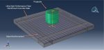
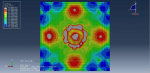
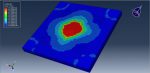
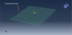
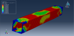
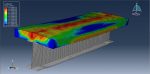
Workshop 3: Rigid impact simulation on the ultra-high performance fiber reinforced concrete slab
This tutorial focuses on investigating the impact of a rigid object on an ultra-high-performance fiber-reinforced concrete (UHP-FRC) slab using Abaqus. UHP-FRC is a recently developed type of concrete that offers significantly improved material performance compared to traditional concrete. It possesses exceptional mechanical properties, including a compressive strength exceeding 150 MPa, high elastic modulus, a high elastic limit, tensile strength ranging from 8 to 15 MPa, strain hardening in tension, fracture energy several orders of magnitude higher than conventional concrete, and a high post-cracking capacity. The remarkable compressive strength of UHP-FRC is achieved by utilizing a well-balanced combination of very fine aggregates, ensuring uniformity and dense packing.
The UHPFRC slab is represented as a three-dimensional solid component in the simulation, while the bars are modeled as three-dimensional wire components. The rigid projectile is modeled as a shell component, capturing its impact characteristics on the UHPFRC slab.
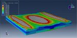
The UHPFRC slab is modeled under an impact load using the Concrete Damaged Plasticity (CDP) approach. The CDP model is capable of predicting damage in both tension and compression during the impact event. The necessary data for the CDP model are obtained from a reference paper.
For the bars within the slab, a steel material with elastic-plastic behavior is selected to accurately represent their mechanical response.
To effectively analyze the impact scenario, the dynamic explicit step is deemed suitable. The simulation incorporates a general contact algorithm with contact properties to account for all relevant contacts. The bars are embedded within the concrete host to accurately represent their interaction.
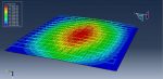
Boundary conditions are applied by assigning fixed constraints to the corners of the slab, ensuring its stability during the impact. Additionally, an initial velocity is specified for the rigid body, representing the impactor.
To achieve reliable results, it is recommended to use a fine mesh in the contact zone to improve the performance of the simulation.
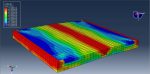
Following the completion of the simulation, various results such as stress, strain, tensile and compression damage, displacement, and more, can be obtained for further analysis and evaluation.
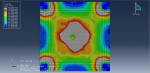
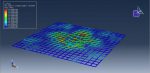
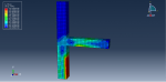
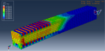
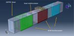
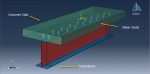
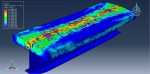
Workshop 4: Air blast simulation over composite panel (UHPFR concrete-Steel plate)
This tutorial focuses on examining the effects of an air blast explosion on a composite panel consisting of Ultra-High-Performance-Fiber-Reinforced (UHPFR) concrete and a steel plate using Abaqus. The UHPFR concrete is represented as a three-dimensional solid component, while the steel plate is modeled as another three-dimensional solid component. The steel bars embedded within the UHPFR concrete are modeled as three-dimensional wire components.
The UHPFRC slab is simulated using the Concrete Damaged Plasticity (CDP) model, which allows for separate definition of compression and tension stresses. This model accurately represents the development of tensile and compressive damage during the blasting process. The steel bars and steel plates are modeled using an elastic-plastic material behavior.
For this type of analysis, the dynamic explicit step is chosen as it is suitable for capturing the transient and dynamic nature of the air blast explosion. The tie constraint is employed to connect the steel plates with the UHPFRC slab, ensuring their interaction is properly accounted for. The steel bars are embedded within the concrete host to accurately represent their behavior.
To simulate the air blast explosion, the CONWEP blast load procedure is utilized. This procedure allows for the modeling of the blast effects on the composite panel.
Fixed boundary conditions are applied to two sides of the panel to provide necessary constraints. It is important to have a fine mesh in order to achieve accurate and reliable results.
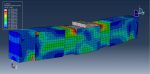
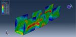
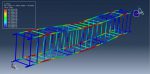
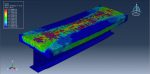
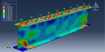
Following the completion of the simulation, various results such as stress, strain, tension and compression damage, and more, can be obtained to analyze the behavior and response of the UHPFRC slab under the air blast explosion.
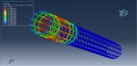
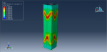
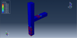
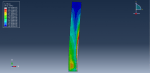
Workshop 5: UHPFRC column with internal CFRP box compression test simulation
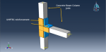
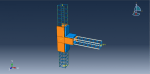
This tutorial explores the simulation of a compression test on a UHPFRC column with an internal CFRP (Carbon Fiber Reinforced Polymer) box using Abaqus. The UHPFRC material is represented as a three-dimensional solid component, while the CFRP internal box is modeled as a three-dimensional shell component. To apply the necessary force, two rigid bodies are employed as a supporter and body in the simulation.
Significant progress has been made in the research and development of concrete over the last three decades, resulting in the development of Ultra High Performance Concrete (UHPC). UHPC exhibits remarkable properties such as high compressive strength, good tensile strength, improved toughness, and enhanced durability. However, UHPC is prone to brittleness, which limits its practical applications. To address this limitation, fibers are often incorporated into UHPC, creating Ultra High Performance Fiber Reinforced Concrete (UHPFRC). The addition of fibers significantly enhances the ductility, fracture toughness, and energy absorption capacity of UHPC.
To accurately model the behavior of the concrete column, the Concrete Damaged Plasticity model is utilized. This model considers the true response of the concrete, taking into account its damage characteristics. The CFRP (Carbon Fiber Reinforced Polymer) box is modeled as an elastic material using Hashin failure criteria to predict the damage that may occur during the simulation.
The simulation employs a general static step with modifications in the convergence model to ensure accurate results. Perfect contact is assumed between the concrete and CFRP materials. A fixed boundary condition is assigned to the bottom rigid plate, while displacement is applied to the top plate to simulate the desired loading condition. It is crucial to use a fine mesh to obtain reliable and precise results.
Upon completion of the simulation, various results such as stress, strain, damage, and the force-displacement diagram can be obtained for further analysis and evaluation.


Sócrates –
This “Ultra-High-Performance Fiber Reinforced Concrete (UHPFRC) structures in Abaqus” training package provides comprehensive learning resources that enable me to acquire techniques and methods for simulating UHPFRC structures in the Abaqus software. The package includes instructional files and tutorial videos designed with practical examples. By utilizing this package, I will be able to accurately simulate UHPFRC structures using Abaqus and gain a deep understanding of their mechanical properties and behavior.