
To model the Composite materials in the Abaqus the best way to do it is using the Composite Layup tool. And that’s the first step. But the challenge is still remains and that’s the damage modeling, which requires the knowledge about the Damage criteria. Unidirectional Composite damage analysis, or composite laminate damage modeling, it doesn’t matter. You need to learn the basics first.
in this blog post you will learn the basic knowledge about the Unidirectional and laminate composite damage mechanisms. Also, you will learn how to model the composites in the Right way.
1. What is unidirectional Composite?
A unidirectional composite is a type of composite material where the reinforcing fibers are all aligned in one direction. This is in contrast to woven composites, where the fibers are crisscrossed in a weave pattern.
The main advantage of unidirectional composites is that they offer very high strength and stiffness in the direction of the fibers. This is because all the fibers are working together to resist force in that direction. However, they are weaker in other directions.
Unidirectional composites are often used in applications where high strength-to-weight ratio is important, such as in aerospace and automotive components.
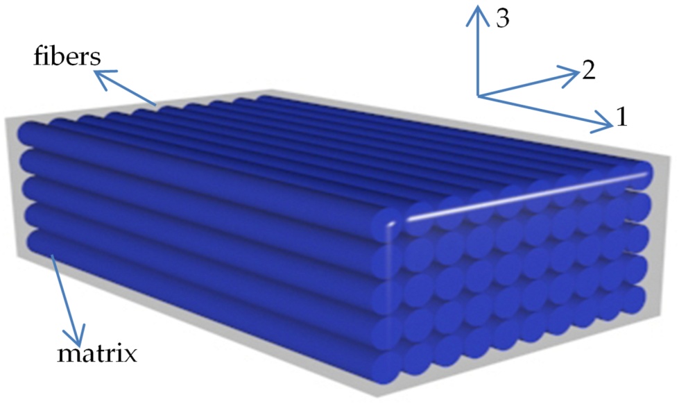
Figure 1: unidirectional composite
2. Unidirectional composite material properties
Unidirectional composite materials, like carbon fiber reinforced polymers (CFRP), are crucial for engineering applications due to their exceptional strength-to-weight ratio and stiffness. However, their unique properties require specific attention when modeling their behavior in Abaqus software.
Key takeaway: Accurately defining the Unidirectional composite material properties is essential for simulating unidirectional composite damage in Abaqus.
These properties fall into two main categories:
- Elastic properties: Young’s modulus, Poisson’s ratio, and shear modulus define the material’s response to deformation under load.
- E11: Longitudinal elastic modulus (along the fiber direction)
- E22: Transverse elastic modulus (perpendicular to fiber direction)
- ν12: Longitudinal Poisson’s ratio
- G12: Longitudinal shear modulus
- ν23: Interlaminar Poisson’s ratio (due to transverse isotropy, E33 = E22, ν13 = ν12, and G13 = G12)
- Strength and damage properties: These include tensile and compressive strengths, fracture toughness, and damage initiation criteria. They govern the material’s resistance to failure and the onset of damage.
- S11+ & S11-: Tensile and compressive longitudinal strength (along the fiber direction)
- S22+ & S22-: Tensile and compressive transverse strength
- S12 & S13: In-plane and transverse shear strength
- Additional properties for damage modeling (refer to Abaqus documentation)
Transverse Isotropy:
Unidirectional composites are assumed to be transversely isotropic, meaning properties are the same in all directions perpendicular to the fibers. This reduces the number of independent material constants needed.
Data Availability:
There are two common scenarios for characterizing unidirectional composites:
Limited Lamina Data:
Missing data points are often ν23 (interlaminar Poisson’s ratio) and S23 (transverse shear strength).
Typical values (e.g., ν23 = 0.5 for carbon fiber) can be used with engineering judgement.
Helius Composite Material Database can be a resource for similar materials.
No Lamina Data:
Micromechanics methods can be used to derive properties from fiber and matrix properties.
Analytical calculations (using equations) or finite element analysis (FEA) simulations can be employed.
Analytical methods are faster but less accurate and have limitations.
FEA simulations are more accurate but require specialized software.
By understanding and accurately defining these properties in Abaqus, engineers can create reliable models that predict the behavior of unidirectional composites under various loading conditions. This ultimately leads to better design decisions and improved product performance.
3. What are Damage mechanisms in unidirectional composites?
The unidirectional composite damage encompasses a specialized field within materials science and engineering focused on understanding and mitigating damage in unidirectional composite materials. Unidirectional composites consist of fibers aligned in a single direction within a matrix material, offering exceptional strength and stiffness properties along the fiber direction. However, they are susceptible to various forms of damage, including delamination, fiber breakage, and matrix cracking, which can compromise their structural integrity.
In contrast to metals, the failure of composite materials involves a multifaceted progression that unfolds across multiple stages. While the initial trigger for failure in a composite sample may occur in a specific mode, the subsequent propagation and ultimate failure modes can vary significantly. To understand how damage initiates and grows, we need to look at the microscopic level:
- Fracture of fibers
- Formation of micro-cracks within the matrix
- Separation of fibers from the matrix (debonding)
- Delamination refers to the separation of individual layers within a laminate structure.
You can see these damages in one glance in figure 2.
4. Basics of Composite damage laminate modeling
Composite laminates are the workhorses of the composite world. Unlike unidirectional composites with their single fiber orientation, laminates are built by stacking multiple layers, or plies, where the fibers in each ply run in a different direction (see figure 3). This creates a material that’s incredibly strong and stiff in some directions but also introduces a new challenge: composite laminate damage.
Damage in composite laminates can occur in various ways, and it often starts subtly.
The basic damage mechanisms of the laminate composites are the same as the single layer of unidirectional composites:
- Fiber breakage
- Matrix cracking
- Debonding
Here we also have Delamination. (See figure 4)
Here’s a basic overview of the threats these materials face:
Hidden enemies: Unlike metals that bend or crack visibly, damage in laminates can begin internally. Microscopic cracks might develop in the resin holding the fibers together (matrix cracking) or the bond between fibers and resin might weaken (debonding).
The domino effect: As these initial stages progress, they can lead to more severe damage. Debonding can cause stress concentrations, making the fibers themselves more prone to breakage. Multiple fiber breaks within a ply can then lead to a complete separation of layers, known as delamination, signifying total failure of the laminate.
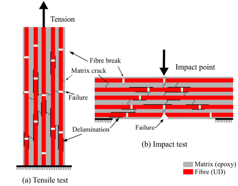
Figure 2: Damage mechanisms in unidirectional composites- Tension & Impact [1]
Note: Unidirectional composites are like the ultimate yes-man in the material world. Super strong in one direction, but try bending them sideways and they’ll fold easier than a deck of cards! This focused strength makes them perfect for things like airplane wings that only need to resist forces from one direction (lift).
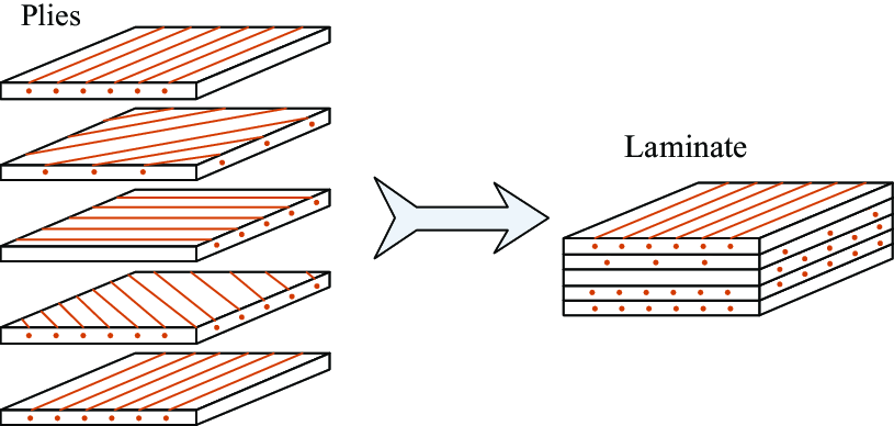
Figure 3: Composite laminate [2]
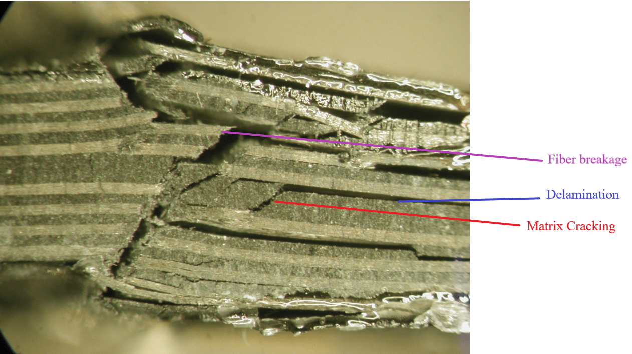
Figure 4: Composite laminate damage modes [6]
Question: How can I learn more about definition of damage and its applications? Where do I look? Also, I need to learn this stuff with some examples. Again, Where? How to model damage in Abaqus? which criteria should I use? I really need some practical examples. (Unidirectional composite damage)
The complexity of laminate damage arises from several factors:
- Multi-directional forces: Unlike unidirectional composites with a single strong direction, laminates experience forces from various angles. This puts stress on different plies depending on the fiber orientation within each ply.
- Interaction of damage modes: Damage doesn’t happen in isolation. Matrix cracking can influence debonding, which in turn affects fiber breakage. Predicting how these factors interact and progress is crucial for understanding overall laminate behavior.
These complexities make it difficult to predict how a laminate will perform under real-world conditions. This is where composite laminate damage modeling comes into play.
Think of it as a virtual testing ground where engineers can simulate how a laminate will behave under different loading conditions. These models can predict:
- Damage initiation: When and where the first signs of damage, like matrix cracking, might occur.
- Damage growth: How these initial cracks or debonding will propagate throughout the laminate.
- Overall performance: How the laminate’s strength and stiffness will degrade as damage accumulates.
There are two main approaches to modeling composite laminate damage:
Failure Criteria
These are simpler methods that set limits for stress, strain, or other parameters. If these limits are exceeded, the model assumes damage occurs. They offer a quick assessment but might not capture the full complexity of damage progression.
Damage Mechanics Models
These are more sophisticated models that simulate the actual damage processes within the laminate. They consider factors like:
- Material properties of fibers, matrix, and their interface.
- The laminate configuration (stacking sequence and ply orientations).
- The type of loading applied (tension, compression, bending, etc.).
By incorporating these details, damage mechanics models can provide a more accurate picture of how a laminate will respond to stress.
Challenges of laminate damage modeling:
- Model complexity: Sophisticated models can be computationally expensive and require advanced material property data, which might not always be readily available.
- Capturing all damage mechanisms: No single model can perfectly capture every possible damage mode that might occur in a real laminate.
- Validation with experiments: The accuracy of any model needs to be verified through real-world testing to ensure it reflects the true behavior of the material.
Now, let’s see how to do unidirectional composite damage simulation in Abaqus.
5. Failure Criteria for Unidirectional Fiber Composites
Unidirectional fiber composites, consisting of aligned fibers embedded in a matrix material, are widely used in aerospace, automotive, and energy applications due to their exceptional mechanical properties. However, their failure behavior is complex and influenced by various factors, including fiber orientation, matrix properties, and interfacial bonding. To predict the failure of these materials, various failure criteria have been developed, which can be categorized into three main groups: (1) fiber-dominated failure, (2) matrix-dominated failure, and (3) interface-dominated failure.
5.1. Fiber-Dominated Failure
Fiber-dominated failure occurs when the fibers are subjected to excessive tensile or compressive loads, leading to fiber breakage or buckling. The most common failure criteria for fiber-dominated failure are:
- Maximum Strain Criterion: Failure occurs when the strain in the fiber direction exceeds a critical value, typically around 1-2%.
Maximum Stress Criterion: Failure occurs when the stress in the fiber direction exceeds a critical value, typically around 3000-4000 MPa.
5.2. Matrix-Dominated Failure
Matrix-dominated failure occurs when the matrix material is subjected to excessive shear or transverse tensile loads, leading to matrix cracking or debonding. The most common failure criteria for matrix-dominated failure are:
- von Mises Criterion: Failure occurs when the von Mises stress in the matrix exceeds a critical value, typically around 50-100 MPa.
Tresca Criterion: Failure occurs when the maximum shear stress in the matrix exceeds a critical value, typically around 30-60 MPa.
5.3. Interface-Dominated Failure
Interface-dominated failure occurs when the bond between the fiber and matrix is compromised, leading to interfacial debonding or sliding. The most common failure criteria for interface-dominated failure are:
- Cohesive Zone Model: Failure occurs when the interfacial stress or energy release rate exceeds a critical value, typically around 10-50 J/m².
Fracture Mechanics Approach: Failure occurs when the interfacial crack growth rate exceeds a critical value, typically around 10^-3 mm/cycle.
5.4. Hybrid Failure Criteria
In reality, the failure of unidirectional fiber composites often involves a combination of fiber, matrix, and interface failure modes. To account for this complexity, hybrid failure criteria have been developed, such as:
- Hashin-Rotem Criterion: A combination of fiber-dominated and matrix-dominated failure criteria.
Puck Criterion: A combination of fiber-dominated, matrix-dominated, and interface-dominated failure criteria.
These failure criteria are widely used in finite element simulations, experimental testing, and design optimization of unidirectional fiber composite structures. However, their accuracy and applicability depend on the specific material system, loading conditions, and experimental validation.
6. How to do Unidirectional composite damage simulation in Abaqus
When you want to do composite damage (unidirectional composite damage) modeling in Abaqus, I think the real challenge lies in the material modeling and damage modeling; the geometry could be difficult sometimes but the real deal is in these two. So, let’s see how to model a single-layer unidirectional composite and laminate in Abaqus.
In Abaqus software, there are several ways to simulate composite materials. Here, we introduce the best one.
You can simulate composite materials using one of the three elements Solid, Continuum Shell, or Shell. Remember that unidirectional fiber composites are typically assumed to be orthotropic.
Example Table you could use. click on them to have access to their tutorial.
| Geometry | Loading | Element type |
| Holed Composite plate | Non-uniform loading | Shell element |
| Holed Composite plate | Non-uniform complex loading | Continuum shell element |
| Multilayer composite cylinder shell | Impact of a bullet | Shell element |
| Multi-layered composite plate | High-speed impact | Shell element |
| Composite plate | Impact | Shell element |
First, you need to define the Elastic properties of the composite. When you do that, you need to define the type of elastic properties, Engineering Constants, Lamina, and Orthotropic.
In the table below you’ll see the difference between them.
| Element type | Elastic material type | Description |
| Shell, Continuum shell | Lamina | Under plane stress conditions, such as in a shell element, only the values of E1, E2, Nu12, G12, G13, G23 are required to define an orthotropic material. |
| Solid | Engineering Constant | Linear elasticity in an orthotropic material is most easily defined by giving the “engineering constants”: the three moduli E1, E2, E3; Poisson’s ratios
ν12, ν13, ν23; and the shear moduli G12, G13, and G23 associated with the material’s principal directions. |
| Solid | Orthotropic | Elasticity by Specifying the Terms in the Elastic Stiffness Matrix |
After that, you need to use the Composite layup tool “![]() ”. When you use this tool depending on your element type (Shell, Continuum shell, or solid) you need to choose one of three options you see in the picture below.
”. When you use this tool depending on your element type (Shell, Continuum shell, or solid) you need to choose one of three options you see in the picture below.
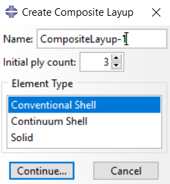
Figure 5: Composite layup element selection
If you select Solid or Continuum shell, the settings would be as follows, which I explain to you in an example:
Imagine we have a 4-layer composite laminate like this [90o, 30o, 40o, 45o]. we have 2 elements in the thickness as depicted below and the thickness of the composite is 6 millimeters.
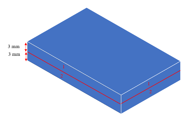
Figure 6: Composite laminate orientation
Now, we need to set these layers in the Edit Composite Layup window as depicted below. In element number 1 the thickness of lamina 90 and 30 are 1 and 2 millimeters, respectively; so, the whole thickness of element number 1 is 3 millimeters and therefore, the element relative thickness of each layer in this element equals 1/3 and 2/3, respectively. Same logic for other layers.
| Element number | Lamina orientation | Thickness (mm) | Element Relative Thickness |
| 1 | 90 | 1 | 1/3 |
| 30 | 2 | 2/3 | |
| 2 | 40 | 2 | 2/3 |
| 45 | 1 | 1/3 |
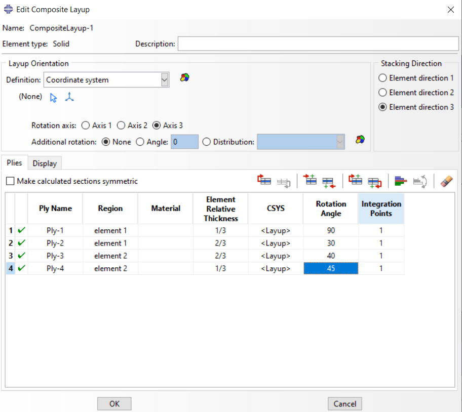
Figure 7: Edit Composite layup window for Solid elements
After that, you need to assign the material orientation, and the composite material modeling is completed. See it in an example: Abaqus composite modeling.
Now, to apply the damage, first you need to know which criteria you want to use. Here is the list of damage criteria: Damage Criteria in Abaqus CAE.
7. Users ask these questions
Now, let’s see the common questions users ask about composite damage and modeling composites. We answered them and offered the proper content (blog or product) for it.
I. 3D Solid elements composite modeling Abaqus/Explicit
Q: Hi,
I have a working VUMAT, but I am unable to run a simulation of a composite plate in Abaqus/Explicit. From what I understand, I can’t use the composite layup feature in Abaqus explicit with solid elements. How should I model my plate then? Thank you.
A: Hello. You can only simulate the elastic behavior of composite material with a 3D continuum element with a special method. You should use the homogenous section. Then, assign a material orientation to specify fiber and matrix direction. If you want to model failure or damage behavior for 3d composite material, you need to write the subroutine. Some subroutines are available in the shop.
|
This package introduces and applies various theories to initiate and progress damage in composite materials based on ABAQUS capabilities for different elements. As you know, according to the modeling done by the micro or macro method, the way of defining the Abaqus composite damage completely follows the separate method in ABAQUS. This training package is customized for macro modeling of composite structures. |
Now, if you need to know how to model damage in composite materials, especially in unidirectional and laminate composites, you should see it in action, which I recommend our complete tutorial. Trust me you won’t regret it. (Unidirectional composite damage)
It would be helpful to see Abaqus Documentation to understand how it would be hard to start an Abaqus simulation without any Abaqus tutorial.
One note, when you are simulating in Abaqus, be careful with the units of values you insert in Abaqus. Yes! Abaqus don’t have units but the values you enter must have consistent units. You can learn more about the system of units in Abaqus.