Why Abaqus Bolt Load Modeling?
Modelling bolts and joints in Abaqus is a crucial aspect of simulating the behavior of various structures under different loading conditions. Bolt load refers to the preload or tension applied to a bolt to ensure secure connections and proper load transfer in structures. Abaqus bolt load modeling is important because it allows engineers to simulate and analyze how these preloads impact the performance, strength, and safety of bolted assemblies under various conditions, ensuring accurate and efficient designs.
In Abaqus, bolts and joints are modeled using various techniques, including solid modeling, beam modeling, and shell modeling (Abaqus bolt modeling). The modeling approach depends on the complexity of the structure and the loads it is subjected to. In the case of bolted joints, Abaqus allows the user to model the bolts explicitly or implicitly, with the latter being more efficient for large assemblies. Joints can be modeled using a number of techniques, including rigid body connection, tie constraint, and contact modeling. Abaqus also provides a range of contact algorithms, including surface-to-surface contact, node-to-surface contact, and embedded constraint, to model the interaction between parts. Proper meshing is essential to accurately model bolts and joints, with Abaqus providing a range of meshing techniques, including automatic meshing, manual meshing, and adaptive meshing. Adequate modeling of bolts and joints is necessary to ensure reliable simulation results and accurate prediction of the structural behavior under different loading conditions.
You can learn more detail in the description below.
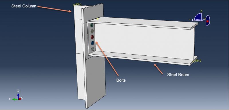
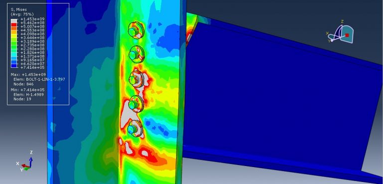
Workshop 1: Simulating the failure of bolts at the connection between steel beams and columns
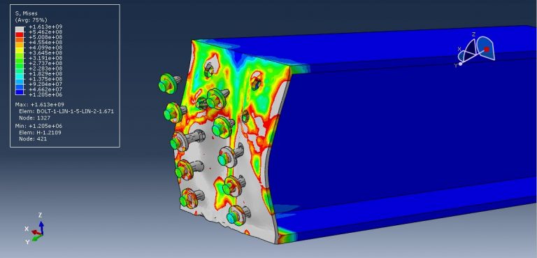
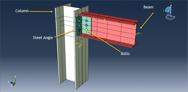
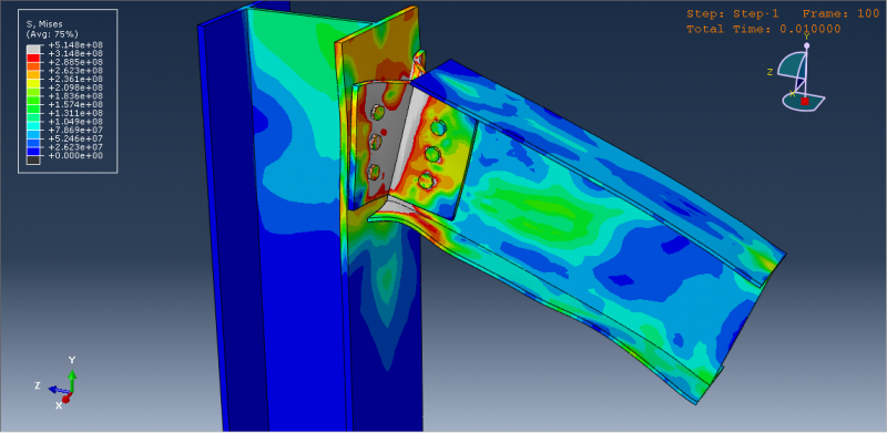
This tutorial explores the simulation of Abaqus bolt failure and examines how the Abaqus bolt load influences the connection between a steel beam and column. The steel beam, column, and bolts are modeled as 3D components.
The steel structure consists of various components, such as beams, columns, and plates, which require connection or fastening to form a cohesive unit. The primary objective of connection design is to create a secure, cost-effective, and straightforward joint. Additionally, it is crucial to establish standardized connections in the structure and design them to allow for adequate clearance and adjustments to account for any misalignment. It is important to ensure that the connections can resist corrosion, are easy to maintain, and have an acceptable appearance.
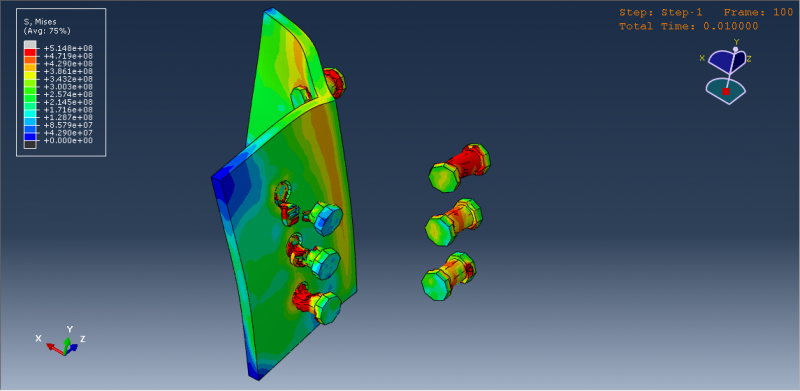
To observe damage and failure in components due to bolt or column failure, the steel structure is modeled using an elastic-plastic material with ductile and shear damage criteria. A dynamic explicit step is necessary because the large deformations cannot be analyzed with a static solver. Surface-to-surface interaction is considered, and a friction coefficient and hard contact properties are assigned for contact. The beam displacement is used as the load, and a fixed boundary condition is assigned to the end of the column. A proper mesh is required for all components using many partitions. After the simulation, results such as stress, strain, damage, and failure can be obtained. The beam’s movement in the Z direction causes significant damage to the bolts, resulting in the failure and removal of some bolts from the structure.
Workshop 2: Air blast simulation over a composite beam
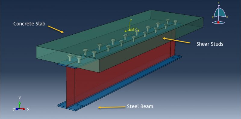
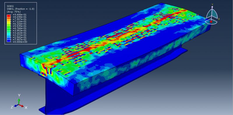
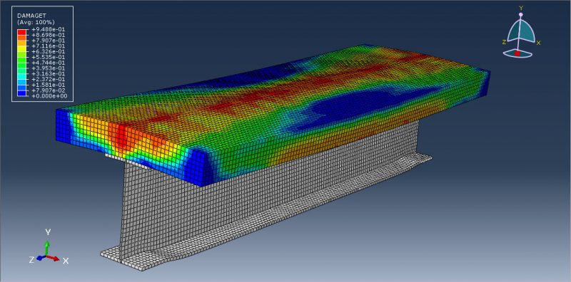
This tutorial focuses on simulating the air blast load on a composite beam (consisting of a UHPFRC-Steel beam with Shear stud) using Abaqus. The Ultra-High-Performance-Fiber-Reinforced Concrete is represented as a 3D solid component. The stud and steel beam are both modeled as 3D solid and shell parts, respectively. Abaqus bolt modeling and the influence of the Abaqus bolt load are fully described here.
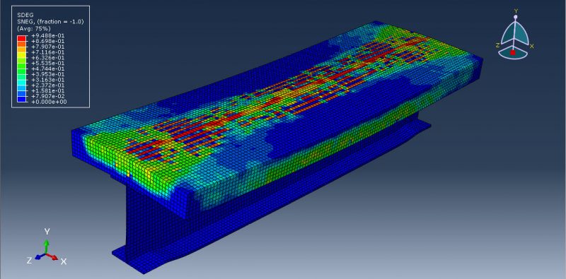
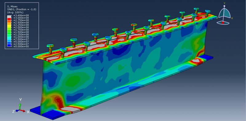
The use of Ultra High-Performance Fiber Reinforced Concrete (UHPFRC) improves the durability, service life, and performance of structures. Over the past few decades, there have been three major developments in cementitious composites, including significant increases in compressive strength, ductility, and workability. These achievements are the result of granular packing optimization, the development of Fiber Reinforced Concrete (FRC), and better understanding of material rheology. The development of Self-Compacting Concrete (SCC) and later UHPC and UHPFRC were facilitated by improvements in models that describe concrete flow. The Concrete Damaged Plasticity is used to model the UHPFRC beam under the blast load, while the Johnson-Cook hardening and damage model is selected to simulate steel stud and beam behavior under severe blast load. A dynamic explicit step is appropriate for this type of analysis. The general contact capability with contact property is selected, and surface-to-surface contact or embedded constraint can be used to define contacts between studs and UHPFRC. The CONWEP blast load procedure is used to define the explosive load, and a fixed boundary condition is assigned to the two sides of the beam. A fine mesh is necessary to obtain accurate results.
Upon completion of the simulation, all outcomes including stress, strain, tensile damage, deformation, and more become accessible.
Workshop 3: Modeling Bolt Load Abaqus and Dynamic Failure of Bolts at Steel Plate Joints
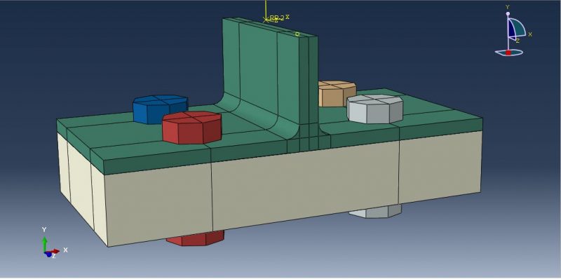
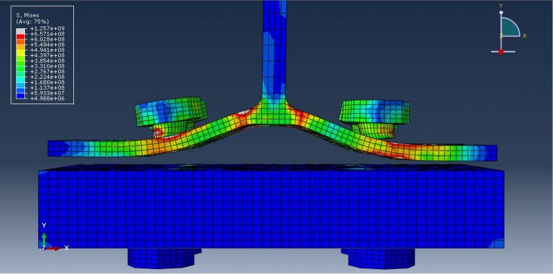
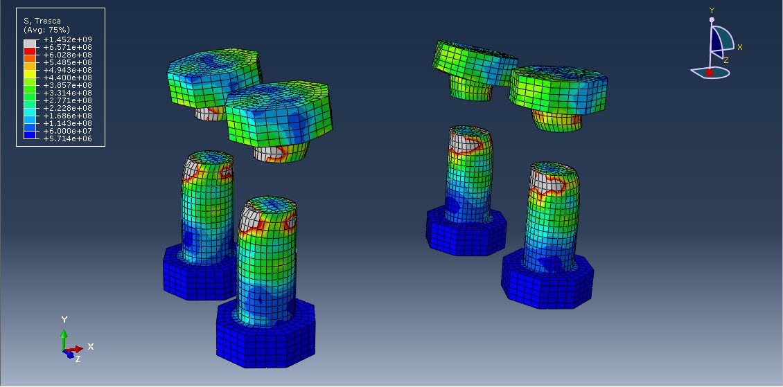
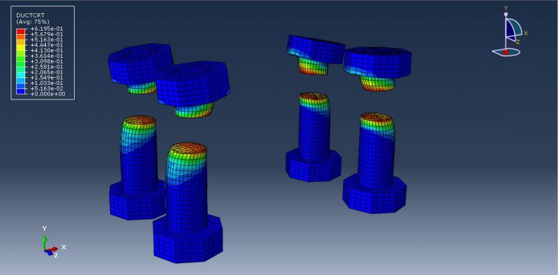
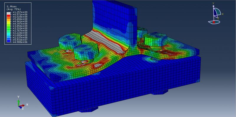
Two primary mechanisms can lead to the fracture of ductile metals: ductile fracture caused by the nucleation, growth, and coalescence of voids, and shear fracture resulting from shear band localization. These mechanisms require different criteria for predicting the onset of damage, based on observational evidence. The ductile criterion is a phenomenological model for anticipating the onset of damage due to void nucleation, growth, and coalescence, while the shear criterion is a phenomenological model for predicting the onset of damage due to shear band localization. To observe damage and failure, these criteria are employed. The dynamic explicit step with a mass-scale technique is utilized to simulate the dynamic failure of the bolts. Surface-to-surface interaction with friction as an interaction property is considered. A fixed boundary condition is assigned to both sides of the bedplate, and displacement with a smooth amplitude is employed to apply a smooth load to the upper steel plate. A fine mesh is required for accurate results, and many partitions are necessary to achieve a good mesh for these components.
All outcomes such as stress, strain, damage, failure, and displacement can be obtained once the simulation is completed.
Workshop 4: The simulation of double-angle connections of steel bolts under dynamic load
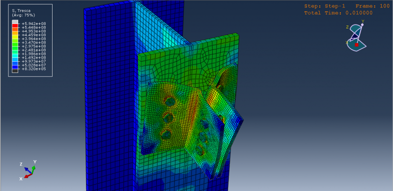
This tutorial examines the simulation of double-angle connections of steel bolts under dynamic load in Abaqus for failure analysis. The beam and column are represented as 3D solid components, while the bolts are modeled using 3D solid parts.
Once the simulation is complete, all outcomes such as stress, strain, damage, failure, and more become accessible.
It would be useful to see Abaqus Documentation to understand how it would be hard to start an Abaqus simulation without any Abaqus tutorial.
If you need to find the reaction forces of the components or the structures, I think this article could help you out: “Getting total reaction force in Abaqus | Complete guide”.
If you are keep getting Negative Eigenvalue warnings, read this article to understand how to deal with it: “Causes and Solutions for Abaqus Negative Eigenvalues warning”.







Tae Young –
I was thrilled to explore the content of the “Bolt Modeling in Abaqus” website, and I must say that it is an incredibly valuable resource for individuals interested in modeling bolts and connections in Abaqus software. The site provided me with extensive tutorials and materials on bolt modeling and connections in Abaqus, equipping me with the necessary knowledge and skills to properly design and simulate the behavior of structures under various loading conditions.
Experts Of CAE Assistant Group –
Thanks for your comment.
Andrew –
This package is an extremely valuable and insightful educational resource. The simulation of bolt failure in the connection between beams and columns, taught in this package, is highly practical and widely applicable.
Experts Of CAE Assistant Group –
Thanks for your comment. It helps costumers to make good decision
Michael Fontenot –
I was somewhat disappointed in the content. I expected information on both implicit and explicit bolt modeling and the different types of each and the pros and cons of each. Also there was no treatment of pretensioning.
Experts Of CAE Assistant Group –
Sorry for your experience. Please read the content and syllabus carefully before purchase.