Abaqus Concrete structure Modeling Full Tutorial

(10 customer reviews)

 600.0

The package includes 19 workshops on topics such as concrete, beam-column structures, composites, steel rebars, Ultra-High-Performance-Fiber-Reinforcement Concrete columns, CFRP bars, hollow-core square reinforced concrete columns wrapped, damaged concrete beams, High Strength Concrete(HSC),ECC/Concrete Composite Beam-Column Joints, circular concrete-encased concrete-filled steel tube (CFST) stub columns, and etc. Every tutorial includes all needed files and step-by-step English videos and is explained from A to Z. Package duration: +600 minutes

We also offer similar budget-friendly packages that include the workshops from this package.

Since these packages do not include the lessons and contain a limited number of workshops, they are available at a lower price (250 euros each).

However, we recommend choosing the current full package instead of purchasing parts 1 to 4 separately, as it includes all 20 workshops and exclusive lessons not available on similar platforms, while still being priced lower than competing offerings.


Included

.inps,video files, Fortran files (if available), Flowchart file (if available), Python files (if available), Pdf files (if available)

Tutorial video duration

+500 minutes

language

English

Level

Package Type

Software version

Applicable to all versions

39 People watching this product now!

Frequently Bought Together

Concrete structure Abaqus + UHPFRC + +
Price for all: Original price was: € 1089.0.Current price is: € 816.7. Save  272.3
Description

Abaqus Concrete structure Modeling Full Tutorial

If you are a researcher, student, university professor, or  Engineer in the company in the field of civil engineering, Abaqus concrete structure modeling package in simulating concrete and structural Engineering is the best selection.
All facets of concern modeling and simulation are covered in this full tutorial. The package includes 19 workshops on topics such as concrete, beam-column structures, composites, steel rebars, Ultra-High-Performance-Fiber-Reinforcement Concrete columns, CFRP bars, hollow-core square reinforced concrete columns wrapped, damaged concrete beams, High Strength Concrete(HSC),ECC/Concrete Composite Beam-Column Joints, circular concrete-encased concrete-filled steel tube (CFST) stub columns, and etc.

You can see the syllabus and details of this workshop below or the drop-down menu on the right side of this product page.

Abaqus tutorial     It will guide you going from the basics up to complex simulation techniques. It is very fluid, and comprehensive and every single detail is explained.

Abaqus tutorial    Every workshop goes straight to the point, without any worthless piece of content. You will learn what you need at every stage and you will be putting it into practice from the very first day.

Abaqus tutorial        Most importantly, we support you as you learn in this course. You can contact our experts to ask your questions and enjoy our modelling and simulations step-by-step support.

What are the exact contents of each video in this package?

It should be noted that this package includes only workshops; there is no lesson at the beginning of each workshop, contrary to our other main training packages.

This video training package contains more than 300 minutes of video tutorials. Click on the chapters of each lesson in the right section of this tab to know the details of the tips and issues presented in this very comprehensive and useful  ABAQUS course package.

It would be useful to see Abaqus Documentation to understand how it would be hard to start an Abaqus simulation without any Abaqus tutorial.


Read More: Abaqus download edition | How to download Abaqus?


Workshop 1: Simulation of Ultra-High-Performance-Fiber-Reinforcement Concrete column in cyclic loading

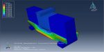
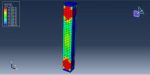
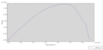
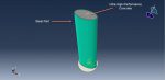
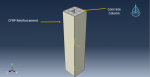
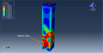
This workshop covers the simulation of cyclic loading on an Ultra-High-Performance Fiber-Reinforced Concrete (UHPFRC) column in Abaqus. The column is modeled as a three-dimensional solid structure.

UHPFRC is a specialized concrete made from Portland cement, reactive admixtures, fine aggregates, inert additives, superplasticizers, and surface-treated steel fibers. The optimized grading of its components results in a high packing density, providing exceptional strength, ductility, and durability. While high-strength cement-based materials typically fail suddenly after cracking, the addition of fibers delays the formation of interconnected microcracks and enhances the material’s toughness through fiber-matrix interactions. This behavior gives UHPFRC a pseudo-strain-hardening response post-cracking, followed by strain localization at peak load and a gradual loss of strength until failure. The material’s inelastic behavior—such as matrix cracking, fiber debonding, and slip—contributes to its high ductility and energy absorption capacity.

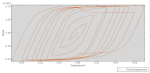
In this workshop, the Concrete Damaged Plasticity model is used to represent UHPFRC under cyclic loading. Material properties are derived from reference studies. The analysis is performed using a general static step with convergence modifications. To generate the hysteresis diagram, displacement and reaction force data are collected. The cyclic load is applied to the top surface of the column following a predefined amplitude, while the bottom surface is fixed. A fine mesh is necessary to ensure accurate results.

After the simulation, results such as stress distribution, strain evolution, and the hysteresis diagram will be available.

Workshop 2: Finite element simulation of Ultra-High-Performance Concrete beam-column joint in cyclic loading

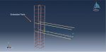
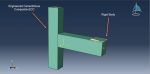
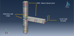
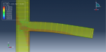
This workshop examines the simulation of an Ultra-High-Performance Concrete (UHPC) beam-column joint subjected to cyclic loading in Abaqus. The UHPC beam-column joint is modeled as a three-dimensional solid part, while the steel bars and strips are represented as three-dimensional wire parts.

UHPC is an advanced concrete technology known for its exceptional strength in compression and tension, high ductility, and durability. In this study, UHPC material properties are used to model the beam-column behavior under cyclic loading. The Concrete Damaged Plasticity (CDP) model requires separate compression and tensile data, while the elastic-plastic material model is applied to the steel bars and strips.

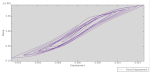
To simulate cyclic loading, a general step with adjustments in the divergence model is used, and the necessary outputs are requested to generate the hysteresis diagram in the visualization. The embedded region constraint is applied to ensure proper interaction between the steel bars, strips, and the concrete host. Fixed boundary conditions are assigned to both the top and bottom surfaces of the column, while cyclic displacement is applied to the free end of the beam following a predefined protocol. A fine mesh is essential to obtain accurate results.

After the simulation, results such as stress, strain, displacement, and the hysteresis diagram will be available.

Workshop 3: Dynamic compression test of in concrete column reinforced with CFRP bars

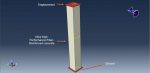
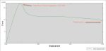
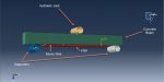
This workshop focuses on the dynamic compression test simulation of a concrete column reinforced with CFRP bars in Abaqus. The concrete column and CFRP bars are both modeled as three-dimensional solid parts, while two rigid bodies—a supporter and a hydraulic jack—are included in the setup.

To accurately represent the behavior of concrete and account for its damage, the Concrete Damaged Plasticity (CDP) model is used. This continuum-based plasticity model considers tensile cracking and compressive crushing as the primary failure mechanisms. The CFRP bars are modeled using an elastic engineering constants approach.
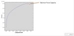
dynamic explicit step is employed to capture failure zones and determine the maximum force capacity of the column. The explicit solver is preferred over a static solver due to the significant convergence issues that occur in this type of analysis. A general contact algorithm is applied to manage all interactions within the contact domain, with friction defined as a contact property. The interaction between the CFRP bars and concrete is assumed to be ideal (perfect contact). Boundary conditions include a fixed constraint on the bottom rigid body, while displacement is applied to the top. A fine mesh is essential for achieving accurate results.

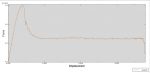
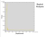
After completing the simulation, results such as stress distribution, plastic strain, tensile and compression damage, and the force-displacement diagram are available.

Workshop 4: Finite element Analysis of hollow-core square reinforced concrete columns wrapped with CFRP under compression

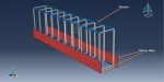
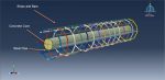
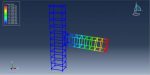
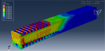
This workshop examines the simulation of hollow-core square reinforced concrete columns wrapped with CFRP under compression in Abaqus. The concrete column is modeled as a three-dimensional solid part, while the CFRP wrap is represented as a three-dimensional shell part. The steel bars and strips are defined as three-dimensional wire parts, and a rigid shell body is included to apply the load.

Transverse FRP wrapping along the column’s axial direction is widely used, as it provides significant confinement pressure to the concrete core under compression. This reinforcement delays concrete crushing and longitudinal steel reinforcement buckling, enhancing both compressive strength and deformation capacity. Among hollow-core columns, those with circular openings demonstrate superior performance compared to those with square openings.

To model the concrete behavior under compression, the Concrete Damaged Plasticity (CDP) model is applied. The steel reinforcement follows an elastic-plastic material model, while the CFRP wrap is defined using elastic lamina properties with Hashin’s damage criterion for failure prediction.

This workshop includes both static and dynamic simulations:

  • In the static analysis, a general static step with modifications to the convergence model is used to prevent premature divergence. The steel bars and strips are embedded inside the concrete host, and perfect contact is assumed between the outer concrete surfaces and the CFRP wrap. The bottom of the column is fixed, and displacement loading is applied through the rigid part. Due to material failure and damage progression, the static simulation requires significant computation time and may be substituted with a dynamic analysis.
  • In the dynamic analysis, a dynamic explicit step with mass scaling is used. This approach efficiently captures failure mechanisms, and the force-displacement diagram provides insights into structural response.

After running the simulations, results such as stress distribution, strain, damage evolution, failure patterns, and the force-displacement diagram are available.

Workshop 5: Axial compression in the damaged CFRP reinforced concrete column with initial residual stress

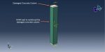
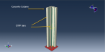
This workshop explores the axial compression simulation of a damaged concrete column with initial residual stress, reinforced with CFRP, in Abaqus. The concrete column is modeled as a three-dimensional solid part, while the CFRP box is represented as a three-dimensional shell part. The analysis consists of two sequential simulations:

  1. First Simulation: The concrete column is subjected to axial loading, generating damage and residual stresses. These results are then recorded for use as initial conditions in the second simulation.
  2. Second Simulation: The CFRP box is introduced, covering the damaged areas of the column, and a new axial load is applied to evaluate the enhanced performance.

To model concrete behavior under axial loading, the Concrete Damaged Plasticity (CDP) model is used, while the Hashin’s damage criterion defines the CFRP response. In the first simulation, two static steps are employed:

  • In the first step, an axial load is applied to the column.
  • In the second step, the load is deactivated to capture the residual stresses and damage state.

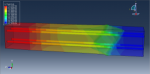
The bottom of the column is assigned a fixed boundary condition, while an axial load is applied to the top surface. The results from this simulation—stress, strain, tensile and compression damage—are then imported as initial conditions for the second simulation.

In the second simulation, the damaged column with residual stress is analyzed, now reinforced with the CFRP box to cover the damaged areas and enhance load capacity. A progressively higher axial load is applied until failure occurs, allowing for a comparison of performance before and after CFRP reinforcement.

Following the simulations, results from both analyses—such as stress distribution, strain, damage progression, and failure patterns—can be compared.

Workshop-6: Damaged concrete beam with initial residual stress reinforced CFRP sheet in bending loading

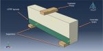
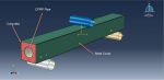
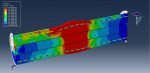
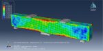
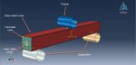
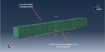
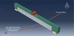
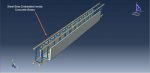
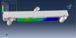
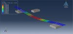
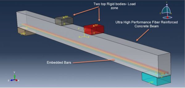
This workshop examines the simulation of a damaged concrete beam with initial residual stress, reinforced with a CFRP sheet under bending load in Abaqus. The concrete beam is modeled as a three-dimensional solid part, while the CFRP sheet is represented as a three-dimensional shell part. The analysis consists of two sequential simulations:

  1. First Simulation: A four-point bending test is performed on the concrete beam to generate stress distribution and damage patterns. These results are then extracted and used as initial conditions for the second simulation.
  2. Second Simulation: The CFRP sheet is applied to the damaged areas of the beam, and the residual stress and damage from the first simulation are imported into the new analysis.

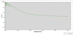
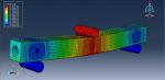
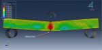
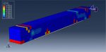
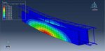
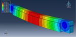
In the first simulation, a general static step with modified convergence settings is used. To ensure that data from this analysis is available for the second simulation, the output results must be saved as an output file. The bending load is applied at two zones of the beam, while boundary conditions are assigned at the beam’s ends. Once the simulation is complete, results such as stress, strain, tensile and compressive damage are obtained.

In the second simulation, the CFRP sheet is introduced to reinforce the damaged zones from the previous analysis. The residual stress and damage state from the first simulation are used as the initial condition for the beam. The CFRP reinforcement is expected to enhance the beam’s performance, allowing it to withstand the same or increased load more effectively.

After completing both simulations, results from each phase—including stress distribution, strain, damage evolution, and structural performance—can be analyzed and compared.

Workshop-7: Damage analysis of concrete beam-column joints simulation in cyclic loading

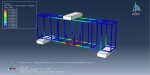
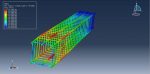
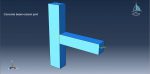
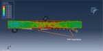
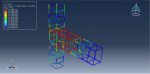
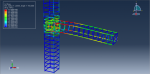
This workshop explores the simulation of concrete beam-column joints under cyclic loading with damage analysis in Abaqus. The beam-column joint is modeled as a three-dimensional solid part, while the steel strips and bars are represented as three-dimensional wire parts.

The steel reinforcement follows an elastic-plastic material model, while the Concrete Damaged Plasticity (CDP) model is applied to account for tensile damage in concrete during cyclic loading. This continuum, plasticity-based damage model considers two primary failure mechanisms: tensile cracking and compressive crushing. The uniaxial tensile and compressive behavior of concrete is defined within this framework, allowing for accurate damage representation. The primary objective of this simulation is to evaluate the concrete damage parameter under cyclic loading.

For this analysis, a general static step is selected. The embedded constraint is used to ensure proper interaction between the steel strips and bars within the concrete hostFixed boundary conditions are applied at both ends of the column, while displacement-controlled loading with an amplitude function is applied at the beam ends following a cyclic loading protocol. A fine mesh is required to achieve accurate results.

Upon completion of the simulation, key results such as tensile damage, compressive damage, stress, and strain distribution are obtained.

Workshop-8: FEM analysis of Elliptical ultra-high-performance concrete-filled steel tabular column under a compression loading

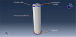
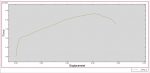
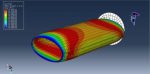
This workshop explores the simulation of an elliptical ultra-high-performance concrete-filled steel tubular (CFST) column under compression loading in Abaqus. Elliptical CFST columns have gained significant attention due to their enhanced strength and stiffness compared to empty elliptical hollow sections. The UHPC core is modeled as a three-dimensional solid part, while the steel tube is represented as a three-dimensional shell.

CFST columns are widely used in buildings, bridges, transmission towers, and offshore structures because of their high strength, stiffness, ductility, and energy absorption capacity. These composite columns consist of circular or rectangular steel tubes filled with concrete, and the elliptical CFST column is a more recent variation where concrete is filled into an elliptical steel tube.

To model the UHPC core, the Concrete Damaged Plasticity (CDP) model is used, with material properties obtained from reference studies. The steel tube follows an elastic-plastic material model, incorporating a ductile damage criterion. The simulation is performed using a general static step with modifications to improve convergence.

perfect or ideal contact is assumed between the steel tube and the concrete core, and general contact with frictional properties is applied to all interacting components. The bottom rigid body is fixed, while displacement with an amplitude function is applied to the top rigid body to simulate compression. A fine mesh is essential for achieving accurate results.

After completing the analysis, results such as stress, strain, damage progression, and the force-displacement diagram are available.

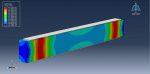
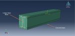
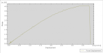
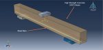
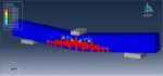
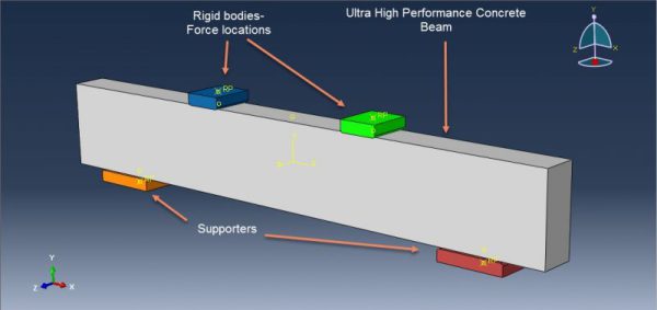
This workshop explores the simulation of a three-point bending test on a High Strength Concrete (HSC) beam in Abaqus. The key distinction between high-strength concrete and normal-strength concrete lies in their compressive strength, which measures the concrete’s ability to withstand applied pressure. While there is no clear threshold between the two, high-strength concrete is manufactured by optimizing the materials that make up normal-strength concrete. Producers adjust factors such as cement quality, aggregate selection, and the proportions of cement, water, aggregates, and admixtures to achieve the desired strength. The HSC beam is modeled as a three-dimensional solid part, and the steel reinforcement is modeled as a three-dimensional wire part.

The nonlinear behavior of concrete is modeled using the built-in Concrete Damage Plasticity (CDP) model in Abaqus. Four key input parameters are required to fully define the yield surface and flow rule in the three-dimensional stress space: dilation angle (ψ)plastic flow potential eccentricity (є)the ratio of biaxial strength to uniaxial strength (σbo/σco), and the shape factor (Kc), which defines the yield surface in the deviatoric plane. CDP data for HSC is extracted from reference literature. The steel bars are modeled with elastic-plastic behavior. A general static step with adjustments to the convergence model is used.

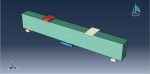
Surface-to-surface interaction with a friction coefficient is applied between the HSC beam and the rigid bodies. The bars are embedded within the HSC beam, and fixed boundary conditions are applied at the bottom of the beam. A displacement with amplitude is applied to the top rigid body. A fine mesh is necessary to achieve accurate results.

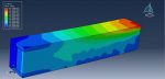
After running the simulation, results such as stress, strain, tensile damage, and the force-displacement diagram are available.

Workshop-10: Flexural behavior of reinforced concrete beams strengthened with ultra-high performance concrete Analysis in Abaqus

In this workshop, the simulation of the flexural behavior of reinforced concrete beams strengthened with ultra-high-performance concrete (UHPC) in Abaqus has been conducted. Strengthening concrete structures is crucial not only for deteriorating structures but also for enhancing the performance of new concrete members under service conditions. This process is particularly important for critical infrastructures like power stations, nuclear plants, and marine structures, where demolition is often economically and technically unfeasible unless strengthening techniques fail to meet performance requirements. Ultra-high-performance concrete (UHPFRC) has emerged as a modern material used for repairing and strengthening reinforced concrete (RC) structures. The concrete beam and UHPC cover are modeled as three-dimensional solid parts, while the bars and strips are modeled as three-dimensional wire parts.

The Concrete Damaged Plasticity (CDP) model is used for simulating the behavior of the concrete beam. This is a continuum, plasticity-based damage model that accounts for tensile cracking and compressive crushing as the primary failure mechanisms of concrete. The steel material for the strips and bars is modeled using elastic-plastic behavior, while the UHPC cover uses the CDP plasticity model, with material data taken from reference studies. The simulation uses a general static step, with modifications to the convergence model.

Surface-to-surface contact with friction is applied between the concrete beam and the rigid bodies. The bars and strips are embedded within the concrete matrix. Fixed boundary conditions are applied at the bottom of the beam, with displacement applied to the top rigid body using a smooth amplitude. A fine mesh is recommended to achieve accurate results.

After the simulation, results such as stress, strain, tensile and compression damage, and displacement are available.

Users ask these questions

Concrete! So many things about it and lots of tips regarding its simulation in Abaqus. So, there is no surprise users ask questions about it. We have decided to answer a few of them, which you can see them below.

I. Determination the time and location of the first crack

Q: For my project, I’m using ABAQUS to model an L-shaped shear wall. On the top surface of my specimen, I applied a cyclic loading. “Base shear vs drift data” has been extracted (and obtained a backbone envelope curve from the hysteresis). Aside from this load-deflection curve, I’d like to know when and where the first cracks and crushing of concrete occur. And the same for the yielding of rebars. Is there anyone who can assist me with this?

A: Hello,

First, you need to know what your damage initiation criterion is? After completing your job, select the damage initiation criterion from the Field Output dialog box. Check the frames and legend. Find out when the first point value is greater than one. You can read the time from the step time. To find the point location, select the Contour from the options menu, then go to the Limits tab, and toggle on the Show location to observe the location of the point. Refer to this link to get practical examples of modeling concrete: “https://caeassistant.com/product/abaqus-concrete-structure-modeling-full-tutorial/

  • Introduction and problem description
  • Description of modeling steps
  • Result and discussion
  • Introduction and problem description
  • Description of modeling steps
  • Result and discussion
  • Unidirectional Composite material damage
  • Workshop 1: Stress Analysis of woven composite plate under compression
  • Workshop 2: Stress Analysis of unidirectional multilayered composite plate under compression
  • Workshop 2: Stress Analysis of composite by RVE (micro modeling) under normal displacement
  • Ductile damage initiation for metals Ductile damage evolution for metals Introduction to Hashin damage initiation for composites Progressive damage for Composites Concrete damage plasticity in tension and how to apply it Concrete damage plasticity in compression and how to apply it Required outputs for CDP How to define composite materials in lamina type How to define Hashin damage evolution for composites How to define isotropic hardening plasticity for metals How to define damage How to create section profile for beam How to define customized coordinate system How to pattern in assembly module What is the settings for outputs of different material types(Concretes, metals, composites) How to embed beam in concrete box How to view result of concrete damage /ductile damage/Hashin damage Plot Force vs displacement in FRP
  • Introduction and problem description
  • Description of modeling steps
  • Result and discussion
  • Introduction and problem description
  • Description of modeling steps
  • Result and discussion
  • Introduction and problem description
  • Description of modeling steps
  • Result and discussion
  • Introduction and problem description
  • Description of modeling steps
  • Result and discussion
  • Introduction and problem description
  • Description of modeling steps
  • Result and discussion
  • Introduction and problem description
  • Description of modeling steps
  • Result and discussion
  • Introduction and problem description
  • Description of modeling steps
  • Result and discussion
  • Introduction and problem description
  • Description of modeling steps
  • Result and discussion
  • Introduction and problem description
  • Description of modeling steps
  • Result and discussion
  • Introduction and problem description
  • Description of modeling steps
  • Result and discussion
  • Introduction and problem description
  • Description of modeling steps
  • Result and discussion
  • Introduction and problem description
  • Description of modeling steps
  • Result and discussion
  • Introduction and problem description
  • Description of modeling steps
  • Result and discussion
  • Introduction and problem description
  • Description of modeling steps
  • Result and discussion
  • Introduction and problem description
  • Description of modeling steps
  • Result and discussion
  • Introduction and problem description
  • Description of modeling steps
  • Result and discussion
  • Introduction and problem description
  • Description of modeling steps
  • Result and discussion
  • Types of heat transfer analysis What is uncoupled heat transfer analysis and how to use it Heat transfer modes (convection, conduction, radiation) Transient vs steady state analysis What is Sequentially coupled thermal-stress analysis and how to use it What is Fully coupled thermal-stress analysis and how to use it What is Adaptive meshing and its advantages What is ALE Adaptive Meshing and its advantages What is Lagrangian method and its advantages Lagrangian Description What is Eulerian method and its advantages What is adiabatic analysis and how to use it Adiabatic formulas Required material inputs for uncoupled steady state Required material inputs for uncoupled steady state Required step settings for uncoupled steady state Required interaction settings for uncoupled steady state Required load settings for uncoupled steady state Required material inputs for transient thermal analysis Apply different types of heat modes Required step settings for uncoupled heat transfer Results of transient vs steady state Required material inputs for sequentially coupled analysis How to import result of heat transfer analysis as an input of stress analysis inputs for sequentially coupled analysis Settings of modulus in stress analysis How to create rigid spline geometry Usage of axisymmetric element in forge analysis Definition of strain-rate and temperature dependent material Required material inputs for fully coupled analysis for deformable parts Required material inputs for fully coupled analysis for rigid parts Required interaction settings for fully coupled analysis What is thermal conductance and how to apply it Required inputs in edit attribute for fully coupled analysis Required outputs in step module for fully coupled analysis Abaqus Settings for ALE Adaptive meshing How to show Axisymmetric model as a full model What is Johnson-Cook plasticity and its formula How to define Johnson-Cook plasticity How to calculate equivalent force during impact Plot velocity vs time of impactor Effect of time period in impact analysis
  • Introduction
  • Workshop 1: ABAQUS Sequential project
  • Introduction to Lemaitre damage model
  • Writing the Lemaitre subroutine
  • Workshop: Implementation of Lemaitre damage model in upsetting Process

Workshop-11: Finite element simulation of ECC/Concrete Composite Beam-Column Joints in axial loading

This workshop examines the simulation of ECC/Concrete composite beam-column joints subjected to axial loading in Abaqus. In conventional reinforced concrete frame structures, the seismic response is largely determined by the deformation capacity of critical components like beams, columns, and their joints. During seismic events, these elements must sustain significant inelastic deformations while maintaining their load-bearing capacity. Beam-column joints, in particular, bear vertical loads from beams and slabs, as well as horizontal forces from earthquakes and wind, resulting in complex stress distributions in the joint region.

Recently, high-performance fiber-reinforced cementitious composites, known as engineered cementitious composites (ECC), have been introduced in construction to address concrete’s brittleness. ECC exhibits similar tensile and compressive strength to conventional concrete but differs significantly in deformation behavior. While traditional concrete fails suddenly upon reaching its tensile strength, ECC demonstrates strain-hardening characteristics, allowing for continued load-bearing capacity beyond the initial crack formation through multiple micro-cracks.

In the simulation, the beam and column are modeled as a single solid part, while reinforcement strips and bars are defined as three-dimensional wire elements. The concrete’s mechanical response is represented using the Concrete Damaged Plasticity model, with material properties sourced from reference literature. Steel reinforcement follows an elastic-plastic behavior. A general static step is applied to the analysis, and a surface-to-surface contact algorithm is used between the rigid plate and the concrete beam. Reinforcement bars and strips are embedded within the concrete, with fixed boundary conditions at both ends of the column and a displacement-controlled loading applied via the rigid plate. A refined mesh is necessary for accurate results.

Following the simulation, various results such as stress distribution, strain, and force-displacement responses can be extracted.

Workshop-12: Circular concrete-encased concrete-filled steel tube (CFST) stub columns simulation subjected to axial compression

This workshop explores the simulation of circular concrete-encased concrete-filled steel tube (CFST) stub columns under axial compression in Abaqus. Compared to conventional CFST columns, concrete-encased CFST columns offer advantages such as increased stiffness, improved connectivity with reinforced concrete (RC) beams, and enhanced resistance to fire and corrosion. Additionally, the presence of both inner and outer concrete layers allows for the use of thinner steel tubes while maintaining structural integrity. When compared to traditional RC columns, these composite columns exhibit superior strength and ductility, enabling the incorporation of high-strength concrete in the inner CFST, which reduces the required cross-sectional area.

During construction, the inner CFST is assembled first, providing temporary support to bear construction loads before the outer RC component is added. Once the external formwork and reinforcement are installed, the outer concrete is cast. Various configurations exist depending on the combination of section shapes, including square or circular inner CFST and square or circular outer RC. The concrete core, steel tube, and external concrete components are represented as three-dimensional solid elements, while reinforcement strips and bars are modeled as wire elements.

For material modeling, an elastic-plastic behavior is assigned to the steel strips and bars. The steel tube is also defined with an elastic-plastic model, incorporating a ductile damage criterion to capture failure mechanisms. Concrete components are modeled using the Concrete Damaged Plasticity approach, which accounts for tensile cracking and compressive crushing as primary failure modes. Two different analysis procedures are performed in this study: a general static step for static compression, which provides highly reliable results but requires longer computation time, and a dynamic simulation to reduce processing time while maintaining accuracy. The contact interactions are modeled using a general contact algorithm, assuming perfect contact between the concrete core and the steel tube’s inner surface, as well as between the steel tube’s outer surface and the surrounding concrete. A fixed boundary condition is applied at the base, while displacement-controlled loading is introduced at the top. A refined mesh is necessary for achieving stable convergence.

Upon completion of the simulation, results such as stress, strain, tensile and compressive damage, and force-displacement behavior can be extracted.

Workshop-13: Axial compression loading simulation in the Ultra-High-Performance Fiber Reinforced Concrete Column

This workshop examines the simulation of a reinforced concrete (RC) column incorporating ultra-high-performance fiber-reinforced concrete (UHP-FRC) under compressive loading in Abaqus. UHP-FRC represents an advanced class of concrete with superior mechanical properties, including a compressive strength exceeding 150 MPa, tensile strength ranging between 8-12 MPa, and significantly higher fracture energy compared to conventional concrete. The column is modeled as a three-dimensional solid component, while reinforcement bars and strips are represented as three-dimensional wire elements.

The nonlinear behavior of the concrete is characterized using the Concrete Damage Plasticity (CDP) model available in Abaqus. This model is well-suited for capturing the response of both plain and reinforced concrete under various loading conditions. The CDP approach is chosen due to its ability to define independent yield strengths, strain rates, and damage parameters in both tension and compression. Additionally, it enables a refined representation of different concrete types through experimentally determined parameters, primarily used to establish the yield surface and flow rule in three-dimensional stress space. Tension and compression damage parameters are incorporated to predict material degradation during the compression test.

For the simulation setup, a general static step is employed, and surface-to-surface interaction properties are applied between the rigid bodies and the concrete column. Reinforcement bars and strips are embedded within the concrete. The base is assigned a fixed boundary condition, while a displacement-controlled load is applied at the top. A well-refined mesh is essential to ensure accurate results.

Upon completing the simulation, various results such as stress, strain, tensile and compressive damage, and the force-displacement response can be obtained.

This workshop covers the simulation of a concrete beam subjected to static and dynamic bending in Abaqus. The beam is modeled as a three-dimensional solid element, while five rigid bodies are incorporated to represent force application and support conditions.

To capture the behavior of concrete under bending loads in both static and dynamic conditions, the Concrete Damage Plasticity (CDP) model is utilized. This model assumes isotropic damage and is designed to handle various loading scenarios, including cyclic loading. It accounts for the degradation of elastic stiffness due to plastic deformation in both tension and compression, as well as stiffness recovery effects under cyclic loading. The CDP model is applicable in both static and dynamic simulations.

For the static analysis, a general static step is employed. However, due to the occurrence of tensile and compressive damage in the concrete, convergence issues may arise. To mitigate premature convergence failure, adjustments are made in the step settings. In the dynamic analysis, a dynamic explicit step is used, which inherently improves numerical stability and mitigates convergence difficulties.

Contact interactions are modeled using a surface-to-surface contact approach with predefined interaction properties. Fixed boundary conditions are applied to the three lower rigid bodies, while a displacement-controlled load is imposed on the top rigid bodies. A well-structured mesh is essential to obtain reliable results.

In the static simulation, due to convergence limitations at a specific point, tensile and compressive damage occur, causing the analysis to terminate. However, the peak force capacity can still be determined from the force-displacement diagram. In the dynamic simulation, convergence issues are resolved, allowing the analysis to complete successfully. The force-displacement results from the dynamic analysis indicate a similar peak force as observed in the static case, followed by degradation and a noticeable decline in force.

Workshop-15: Simulation of Flexural Behavior of Concrete Filled Square Steel Tube in Inner CFRP Circular Tube

This wokshop explores the flexural behavior of a concrete-filled square steel tube (CFST) with an internal CFRP (carbon-fiber-reinforced polymer) circular tube using Abaqus. With advancements in concrete technology and increasing structural demands, high-strength concrete has become widely used in construction. However, its brittle nature poses challenges, which can be mitigated by enclosing it within a steel tube. This hybrid structural system consists of an outer square steel tube, an inner CFRP circular tube, and concrete filling the space between them. The combination of these materials enhances overall mechanical performance by leveraging the strength of steel, CFRP, and high-strength concrete.

The key advantage of CFST columns lies in the composite interaction between their components. The steel and CFRP tubes exert confining pressure on the concrete, placing it in a tri-axial stress state and improving its strength. Simultaneously, the concrete core enhances the stability of the steel tube, reducing the risk of buckling and increasing overall structural strength. Despite these benefits, the flexural behavior of CFST columns is generally weaker than their compressive performance.

For the simulation, the outer steel box and inner CFRP tube are modeled as three-dimensional shell elements, while the concrete core is represented as a three-dimensional solid element. The behavior of concrete under bending loads is captured using the Concrete Damage Plasticity (CDP) model. The steel box is assigned an elastic-plastic material model with a ductile damage criterion, while the CFRP tube follows an elastic model with Hashin’s damage criterion to predict failure. The dynamic explicit procedure is employed to simulate the bending process, but a quasi-static response can be achieved using a smooth amplitude function.

Contact interactions are defined using a general contact algorithm, incorporating specific properties between the steel tube and concrete to account for separation effects, including friction coefficient, shear stress limits, and elastic slip. The bottom of the structure is fixed, while a displacement-controlled load is applied at the top. A refined mesh is necessary for accurately capturing damage and failure mechanisms.

After completing the simulation, results such as stress, strain, and material damage can be obtained.

Workshop-16: Damage Investigation of the concrete-filled double skin steel tube in dynamic bending

This workshop examines the damage behavior of a concrete-filled double-skin steel box subjected to dynamic bending in Abaqus. The inner and outer steel boxes are represented as three-dimensional shell elements, while the concrete core is modeled as a three-dimensional solid element.

Concrete-filled double-skin tube (CFDST) columns represent an innovative approach to column construction. These columns consist of two concentrically aligned steel hollow sections, with concrete cast in the space between them. The inner and outer steel sections do not necessarily have to share the same cross-sectional shape. This study specifically focuses on CFDST columns constructed using circular steel hollow sections.

To characterize the behavior of steel, an elastic-plastic material model incorporating a ductile damage criterion is employed to predict damaged regions under loading. For the concrete, the Johnson-Holmquist model is utilized, as it is well-suited for both dynamic and quasi-static simulations. A dynamic explicit step is selected for the analysis due to its effectiveness in handling impact-related deformations.

Contact interactions are modeled using a surface-to-surface approach with defined properties such as friction coefficient, shear stress limits, and elastic limits. A general contact algorithm is applied to the remaining interaction domains. The lower rigid parts are assigned fixed boundary conditions, while a displacement-controlled load is applied to the upper rigid part. A refined mesh is necessary to accurately capture damage and crack propagation.

Following the simulation, results such as damage distribution in steel and concrete, stress and strain fields, and the force-displacement response can be obtained.

Workshop-17: Simulation of composite column(steel beam and concrete) in cyclic loading

This tutorial explores the simulation of a composite column, consisting of a steel beam and concrete, subjected to cyclic loading in Abaqus. Both the steel beam and concrete components are modeled as three-dimensional solid elements.

The steel beam is defined using an elastic-plastic material model with a ductile damage criterion to capture damage and failure under cyclic loading. The concrete is modeled with an elastic material formulation combined with the Concrete Damaged Plasticity (CDP) model to predict tensile and compressive damage.

A general static step is utilized for the analysis, with an idealized perfect contact assumed between the steel beam and concrete column surfaces. The lower end of the composite column is assigned a fixed boundary condition, while a displacement-controlled load, following a tabular amplitude protocol, is applied at the top. A refined mesh with appropriate partitioning is required for accurate results.

Following the simulation, outputs such as tensile and compressive damage in concrete, as well as stress and strain distributions for both the steel beam and concrete, can be obtained.

Workshop-18: Failure analysis of concrete cover separation in FRP plated in RC beam

This workshop focuses on the finite element modeling of reinforced concrete beams externally strengthened for flexural performance using side-bonded CFRP laminates in Abaqus. The concrete beam and epoxy adhesive are represented as three-dimensional solid elements, while the CFRP laminate is modeled as a three-dimensional shell element, and the reinforcement bars are defined as three-dimensional wire elements.

Recent advancements in material science have facilitated the development of high-performance composites, particularly fiber-reinforced polymer (FRP) sheets and plates. These composites consist of high-strength continuous fibers embedded in a polymer matrix, providing exceptional mechanical properties such as a high strength-to-weight ratio, resistance to creep and fatigue, and durability in corrosive or harsh environments.

The material behavior is defined using an elastic model combined with the Concrete Damaged Plasticity (CDP) model for concrete, an elastic-plastic model for steel reinforcement, Hashin’s damage criterion for CFRP, and a traction-separation law for the adhesive layer. A general static step is selected for the analysis. Perfect contact is assumed between the concrete and adhesive, as well as between the adhesive and CFRP. Additionally, a general contact algorithm incorporating friction is applied to model interactions among all components. Proper boundary conditions are assigned to the rigid supports. A refined mesh is necessary to improve the accuracy of the results.

Following the simulation, various output results can be obtained, including damage distribution in the CFRP laminate, tensile and compressive damage in the concrete, and failure of the adhesive layer.

Advancements in material science have led to the development of composite materials, particularly fiber-reinforced polymer (FRP) sheets and plates. These materials consist of high-strength continuous fibers, which provide load-bearing capabilities, embedded within a polymer matrix (resin). FRP composites exhibit excellent mechanical properties, including a high strength-to-weight ratio, resistance to creep and fatigue, and durability against corrosion and harsh environmental conditions.

To simulate the behavior of materials in this study, the concrete is modeled using an elastic approach combined with Concrete Damaged Plasticity (CDP), while the steel reinforcement follows an elastic-plastic model. The CFRP is characterized using an elastic model with Hashin’s damage criterion, and the adhesive layer is modeled with an elastic response incorporating a traction-separation law. A general static step is used for the analysis. The interfaces between concrete and adhesive, as well as between adhesive and CFRP, are assumed to have perfect bonding. Additionally, a general contact algorithm with friction is applied to account for interactions among all components. Proper boundary conditions are defined for the rigid supports. A refined mesh is recommended to enhance result accuracy.

Upon completing the simulation, various outputs can be analyzed, including damage in the CFRP laminate, tensile and compressive damage in the concrete, and failure in the adhesive layer.

Workshop-20: steel-concrete composite column simulation in vertical and horizontal loading

This workshop explores the simulation of a steel-concrete composite column subjected to both vertical and horizontal loading in Abaqus. Steel-concrete composite columns are modern structural elements widely utilized for their high load-bearing capacity, efficient material utilization, enhanced stiffness, ductility, and significant energy absorption. Research highlights that combining reinforced concrete (RC) with structural steel sections offers multiple advantages over conventional RC or steel members. The concrete component enhances fire resistance and helps restrain steel sections from buckling. Additionally, the use of steel-concrete composite columns positively influences concrete strain distribution compared to traditional RC columns. However, to prevent concrete spalling under axial loads, fire exposure, or seismic conditions, SRC columns require both longitudinal and transverse reinforcement.

In this study, the concrete column and embedded steel beam are modeled as three-dimensional solid parts, while the reinforcement bars are represented as wire elements, and the pusher plate is treated as a rigid body.

For material modeling, an elastic-plastic approach with a ductile damage criterion is applied to the steel sections, while the Concrete Damaged Plasticity (CDP) model is used for the concrete column. Two separate analysis procedures are conducted: a general static step and a dynamic explicit step, with the results compared at the end of the simulations. The interface between the concrete and steel beam is assumed to be perfectly bonded, and the reinforcement bars are embedded within the concrete. A vertical concentrated force is applied to the top of the column, while a lateral pressure load is applied to the side of the concrete section.

Following both static and dynamic simulations, various results—including stress, strain, damage, displacement, and force-displacement relationships—are obtained.

Shipping and Delivery

All the package includes Quality assurance of training packages. According to this guarantee, you will be given another package if you are not satisfied with the training, or your money is returned. Get more information in terms and conditions of the CAE Assistant.
All packages include lifelong support, 24/7 support, and updates will always be sent to you when the package is updated with a one-time purchase. Get more information in terms and conditions of the CAE Assistant.

Notice: If you have any question or problem you can contact us.
Ways to contact us: WhatsApp/Online Support/Support@CAEassistant.com/ contact form.
Projects: Need help with your project? You can get free consultation from us here.

  • Online payment: with MasterCard, VisaCard and etc.
  • Offline payment: In this payment method, you should pay via PayPal and send your payment receipt as an attached file in the offline payment form.
  • via download link After purchase, a download link will be sent to you a zip file included training videos, documents and software files.
  • Send us your machine ID

To access tutorial video run the .exe file on your personal pc and send the generated code to shop@caeassistat.com and wait for your personal code, which is usable only for that pc, up to 24 hours from CAE Assistant support.

Here you can see the purchase process of packages: Track Order

Features

Abaqus tutorial video
Lecture notes
Abaqus workshop files
Contains all required files
Certification
Works for all Abaqus versions
Safe payment
money-back guarantee
Free 24/7 online mentoring
Access for life
updated content
Time-Saving Short But Full
Premium Corporate and Academic Clients
Prepared by High-Level Researchers
Fortran Abaqus subroutines
All payment method

10 reviews for Abaqus Concrete structure Modeling Full Tutorial

  1. Avatar of Théo

    Théo

    After using this course, my ability to solve real-world problems related to concrete structures improved significantly. The practical exercises and real-world examples in this course were very useful.

  2. Avatar of Otávio

    Otávio

    The content of this course is very comprehensive and complete. All the relevant topics related to concrete modeling in Abaqus are covered.

  3. Avatar of Leônidas

    Leônidas

    This course helped me reach a higher level of proficiency in Abaqus. After completing this course, my self-confidence in tackling concrete projects increased significantly.

  4. Avatar of Caetano

    Caetano

    After using this course, I was able to quickly create and analyze more sophisticated models in Abaqus. The tips and tricks presented in this course were truly effective.

  5. Avatar of Henrique

    Henrique

    The quality of the videos and explanations provided in this course is excellent. The instructor was able to effectively communicate the complexities of concrete modeling in simple and understandable terms.

  6. Avatar of Taís

    Taís

    The content of this course is up-to-date and practical. For example, the sections on UHPFRC and CFRP modeling were very helpful and aligned with the latest research and industry practices. What would your recommendation be for those who are looking to learn concrete structure modeling in Abaqus?

  7. Avatar of Pietra

    Pietra

    This course helped me identify and address my strengths and weaknesses in concrete modeling in Abaqus. The sections related to modeling more complex concrete behavior such as fatigue and damage were particularly useful.

  8. Avatar of Lavínia

    Lavínia

    After taking this course, I was able to model and analyze more complex projects in Abaqus. The practical exercises and solving real-world problems during the course were a great help to me. What additional skills might be needed?

  9. Avatar of Eloisa

    Eloisa

    The quality of the content in this course is excellent. Each topic is covered comprehensively and with sufficient details. Compared to other training resources I had used before, this course was much more complete and useful.

  10. Avatar of Anahí

    Anahí

    This training package helped me gain a deeper understanding of concrete structure modeling in Abaqus. The step-by-step video descriptions and accompanying files were very helpful. After completing this course, my ability to design and analyze concrete structures increased significantly.

Add a review