What is Arc welding?
Arc welding is a widely used fusion process for joining metals, where an electric arc is formed between an electrode and the workpiece. This intense heat melts the metal, allowing it to intermix and create a strong bond upon solidification. Arc welding is employed in various industries for fabricating structures and components, providing durability and strength to the welded joints.
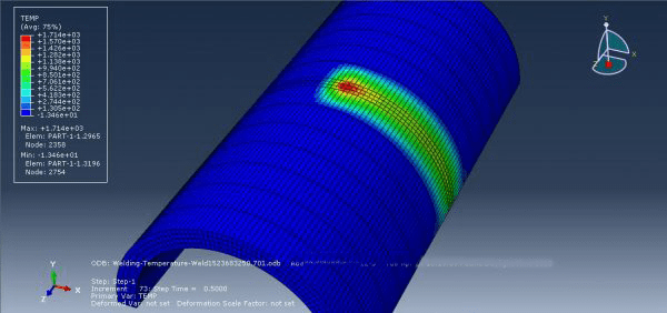
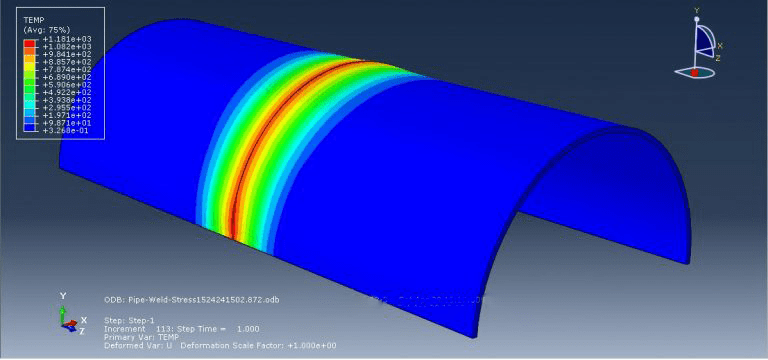
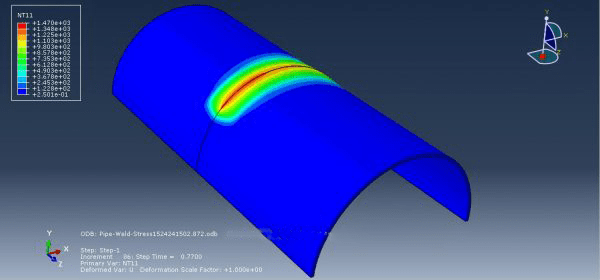
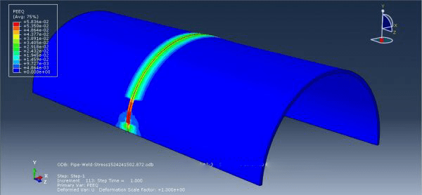
Arc welding simulation in Abaqus (Arc welding Abaqus) is a valuable tool for optimizing the welding process. By using computational models, engineers can predict and analyze important factors such as temperature distribution, residual stresses, distortion, and microstructure evolution during welding. This simulation helps in understanding the behavior of the weldment and allows for the optimization of welding parameters, such as welding speed, heat input, and electrode positioning. By simulating the welding process in Abaqus, engineers can enhance weld quality, improve structural integrity, and minimize the risk of defects, all while reducing costs and the need for physical trial-and-error testing.
Arc welding simulation in Abaqus can help in minimizing several common welding defects by providing insights into the welding process and allowing for optimization. Some of the defects that can be addressed through simulation include:
- Weld Cracking: Simulation can help identify areas prone to cracking due to high residual stresses or improper welding parameters. By optimizing heat input, preheating, and cooling rates, the risk of weld cracking can be minimized.
- Distortion: Welding-induced distortion can affect the dimensional accuracy of welded structures. Simulating the thermal and mechanical behavior of the weld can aid in understanding and minimizing distortion through parameter adjustments or the use of distortion control techniques.
- Lack of Fusion or Incomplete Penetration: Simulation can identify regions with insufficient fusion or incomplete penetration, allowing for adjustments in welding parameters, such as current, voltage, and travel speed, to ensure proper fusion and penetration.
- Porosity: Porosity, caused by gas entrapment during welding, can weaken the weld. Through simulation, gas flow patterns and shielding gas effectiveness can be analyzed, helping to minimize porosity defects.
- Residual Stresses: Welding can induce residual stresses that affect the structural integrity of welded components. Simulation enables the prediction and optimization of welding parameters to minimize residual stresses and their potential impact on performance.
Workshop 1: Arc welding simulation with DFLUX subroutine
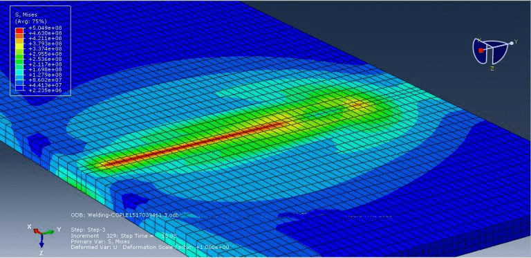
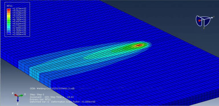
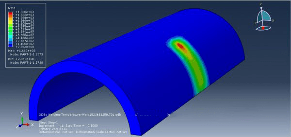
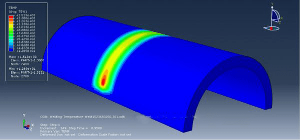
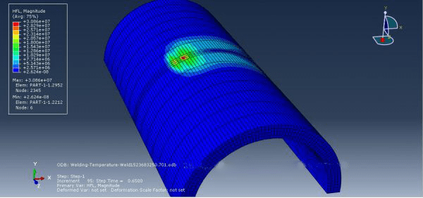
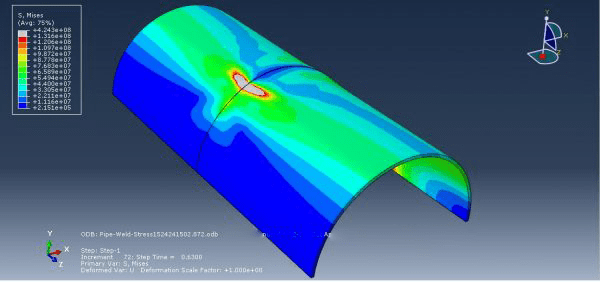
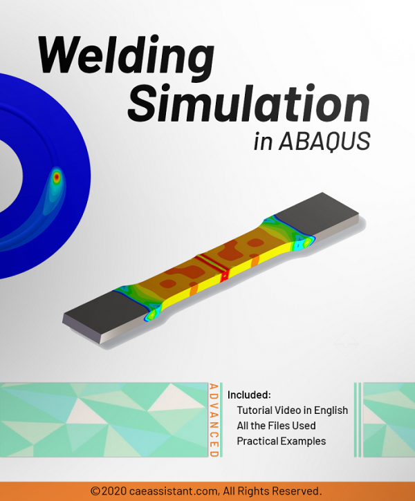
This tutorial provides a detailed demonstration of the arc welding simulation process using DFLUX to accurately determine the uneven distribution of heat. To illustrate this example, a geometry of a piece and its corresponding material properties dependent on temperature were created. Steel material was used, incorporating properties such as elasticity, plasticity, conductivity, expansion, and specific heat based on temperature variations. The heat source applied to the plate results in significant thermal deformations.



piyeha3032 –
Is this package suitable for mechanical engineers or is it primarily intended for civil engineers?
Experts Of CAE Assistant Group –
Yes. it works for both fields, mechanical and civil engineering