Lesson 1: ABAQUS/CAE Introduction
This lesson introduces Abaqus, a powerful software used for engineering analysis. It highlights the different stages involved in using Abaqus, starting with the various types of CAE software and their purposes. We then delve into Abaqus’ user interface, showcasing its functionalities like the menu bar, toolbar, and model window.
The core of the lesson focuses on the process of using Abaqus for analysis. We learn about pre-processing, where you meticulously define your model’s geometry, material properties, and loading conditions. It also covers meshing, a crucial step where the model is divided into small elements for efficient analysis. The lesson acknowledges that this is just a starting point, particularly for beginners, but serves as a stepping stone to further exploration of Abaqus’ capabilities.
Workshop-1- FEM simulation of the human tooth under static loading
Due to the versatile nature of the finite element method (FEM), which allows for the modeling of complex physical phenomena, its use across various disciplines has been expanding, particularly in analyzing the mechanical properties of modern materials. One significant application of FEM today is in bioengineering and dentistry, where it is used to assess stress levels and evaluate strength hypotheses in bone tissues. This enables the design and optimization of advanced materials for dental reconstructions, such as crowns or crown-root fillings, and helps in assessing the risk of failed dental treatments that could damage the hard dental tissue or the filling material. Numerical simulations using FEM in dentistry can serve as a preclinical testing phase for the biomechanical design and optimization of dental fillings.
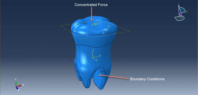
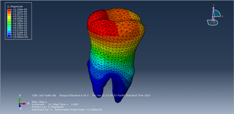
In this tutorial, the finite element simulation of a human tooth under static load is examined. Since Abaqus cannot directly create complex geometries like teeth or skulls, the tooth model is imported into Abaqus as a SAT file. A general static step is used to apply a concentrated force, with fixed boundary conditions set at the tooth’s boundary area. During the simulation, areas of high stress are highlighted, and the results, including stress distribution diagrams, are available in the visualization.
Lesson 2: Finite Element Method Introduction
The finite element method, often abbreviated as FEM, is a powerful tool used to tackle complex engineering problems. Imagine a car under stress – FEM breaks the car down into smaller, simpler pieces called elements. By applying equations to each element and then reassembling them, FEM can predict the car’s overall behavior, like its strength or how it will deform. This approach is widely used in various fields to analyze structures, heat transfer, fluid flow, and more.
In this lesson, the finite element method will be explained step by step.
Workshop-2 Crack growth stimulation of bone in three points bending
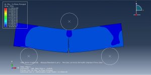
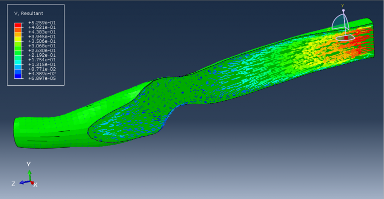
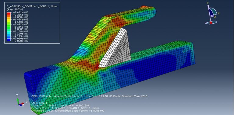
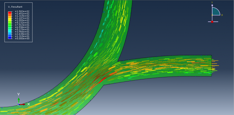
This tutorial examines the simulation of crack growth in bone under a three-point bending test using Abaqus. Researchers are increasingly using the finite element method (FEM) for structural analysis of bones to gain insights into the mechanisms of bone fractures. However, most previous studies have only shown stress or strain distribution patterns without illustrating how fractures initiate, propagate, or how fracture lines grow. Bones can fracture in various ways; for example, a closed fracture does not harm surrounding tissue or break the skin, while a compound fracture, or open fracture, does damage the surrounding tissue and breaks through the skin. Compound fractures are typically more severe due to the risk of infection.
In this study, the bone is modeled as a two-dimensional part with elastic material properties, incorporating a traction-separation law to simulate crack growth. The static analysis combined with the extended finite element method (XFEM) is suitable for this type of simulation.
Lesson 3: Types of analysis
This lesson is one of the most crucial in the FEM simulation tutorial. It provides an in-depth discussion on both explicit and standard solvers within Abaqus. In the first part of this FEA training, the process of selecting an appropriate solver for various examples based on their capabilities will be explained. The lesson outlines the key differences between these two solvers, such as their suitability for different types of problems, the field element type of analysis, contact handling, and their respective solving methods. Additionally, the impact of mesh size on the speed of analysis for both solvers will be examined in the subsequent section.
Workshop-3 Bone drilling simulation using the explicit method
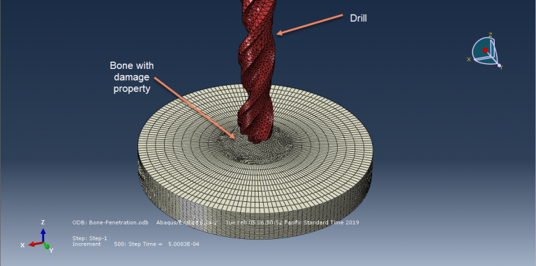
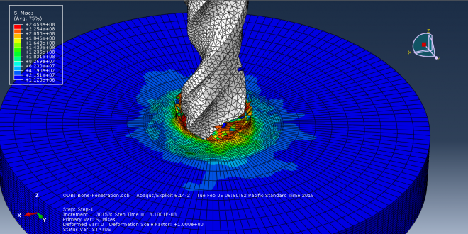
This tutorial investigates the simulation of the bone drilling process using the explicit method in Abaqus. Bone drilling is a common procedure in various surgical fields, including orthopedics, neurosurgery, plastic and reconstructive surgery, craniomaxillofacial surgery, and ENT (ear, nose, and throat) surgery. Typically, a cylindrical tunnel is drilled into the bone to insert a screw or other threaded device, ensuring rigid fixation through the integration of cancellous and/or cortical bone with the screw threads. This configuration makes bone screws resistant to axial and shear forces as well as bending moments, thereby supporting the load-bearing function of the skeleton during movement. Drill-bits are also used to create bony tunnels, such as in anterior cruciate ligament (ACL) reconstruction.
For this type of analysis, a dynamic explicit procedure is appropriate. The simulation includes general contact, considering internal damage and erosion. The drill is applied with a rotational velocity and axial displacement, allowing it to penetrate the bone and create a hole during the simulation.
Lesson 4: Some consideration in EXPLICIT Analysis
In this lesson, crucial tips about explicit solvers are covered. First, various types of analyses conducted using the dynamic explicit solver are explained. Additionally, the concept of the stable time increment and its calculation method are described in detail with precise examples.
In some cases, the speed of analysis can be increased using techniques such as mass scaling and load rate scaling. These techniques are thoroughly explained, including tips for calculating optimal values for their application. Finally, the lesson discusses maintaining energy balance and ensuring that the problem remains in a quasi-static state, as opposed to a dynamic one.
Workshop-4 Simulation of Titanium Foam Behavior for Dental Application
In this tutorial, the finite element simulation of titanium foam behavior as an implant under dynamic load in Abaqus is explored. Metal foams, a novel class of materials, are increasingly used in applications such as structural components, automotive parts, sound and vibration absorbers, heat exchangers, and biomedical implants. This is due to their unique combination of properties like low density, high specific stiffness, high specific strength, and excellent energy absorption capability. Among metal foams, titanium foams (Ti-foams) are preferred for critical applications, including biomedical implants, due to their biocompatibility. The use of cellular metals enhances the friction coefficient between the implant and the surrounding bone, allowing mechanical interlocking through substantial bone ingrowth and providing better long-term stability. Additionally, the stiffness of the implants can be tailored by adjusting the porosity to mitigate the stress shielding effect.
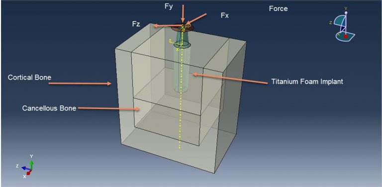
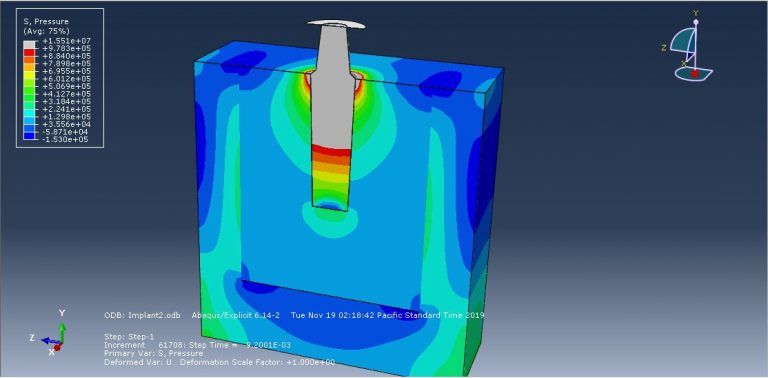
In this simulation, the titanium foam implant and mandible are modeled as three-dimensional solid parts. The mandible consists of cancellous and cortical bone. The titanium foam material is modeled with elastic and crushable foam plastic behavior, using an isotropic type with hardening for the crushable foam model. The cancellous and cortical bone materials are modeled as elastic. A dynamic explicit procedure is employed to simulate the dynamic load on the titanium foam. Surface-to-surface contact is modeled with appropriate properties in the first simulation, while a tie constraint is used in the second simulation to model the contact zone between the bone and the implant. The bottom surface of the mandible is fixed, and a concentrated force is applied in three directions. The mesh is refined at the contact zone. After the simulation, results such as stress, strain, and force are obtainable.
Lesson 5: Heat transfer and Coupled temperature-displacement analysis
One of the most prevalent phenomena in the universe is heat transfer, which can significantly affect mechanical characteristics. Heat transfer analysis can be categorized into two types: steady-state and transient. In this lesson, the settings and tips for conducting both types of analyses are discussed.
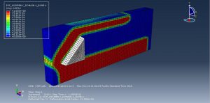
Workshop-5 Numerical modeling of orthogonal cutting of cortical bone
Bone cutting is a common procedure in orthopedic trauma surgery and dentistry, encompassing operations such as grinding, sawing, and drilling. In manufacturing, the proper definition of machining operations is crucial for process efficiency (both time and cost) and surface integrity. This concept also applies to bone cutting, where minimizing cutting time (to reduce overall surgery duration) and ensuring surface quality (to prevent thermal bone damage and potential osteonecrosis) are essential. Validated modeling tools like the finite element method (FEM) can aid in analyzing and defining bone cutting operations. However, achieving accurate simulations requires proper constitutive equations that accurately represent bone behavior.
In this simulation, an Eulerian approach is used, with the Johnson-Cook material model applied to represent bone. A dynamic temperature explicit step is suitable for this type of analysis.
Lesson 6: Damage information in Abaqus
This lesson covers the modeling of reinforced beam-columns using fiber-reinforced polymer (FRP) with bar and composite reinforcements. Initially, all relevant concepts and theories are discussed. The key topics addressed in this lesson include:
- Damage and continuum damage
- Ductile damage of metals
- Hashin damage initiation and progressive damage based on the energy method for composites
- Definition of concrete
- Elastic properties of concrete
- Definition of concrete plastic properties and its behavior under tensile and compressive forces
- Progressive damage behavior of concrete under tensile and compressive stresses
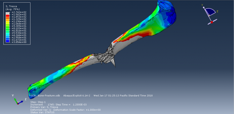
Workshop-6 Simulation of femur bone fracture in rigid impact loading
In this workshop, we conduct a step-by-step simulation of a bone fracture during an impact with a rigid body in ABAQUS. The impactor is modeled as a rigid body with an initial velocity to penetrate the femur bone. The bone geometry is created using Solidworks and then imported into ABAQUS. To predict the fracture area in the bone, the Johnson-Cook (JC) material model is used, providing a suitable plasticity with a damage model for the impact process. To define general contact that considers internal elements, the edit keyboard capability has been implemented.
Lesson 7: Plasticity hardening in Abaqus
This structural engineering Abaqus tutorial lesson covers the concept of hardening in Abaqus software. It begins with a comprehensive definition of the hardening concept, typical types of hardening, and related equations. Several phenomena are also described, including the Bauschinger effect, cyclic hardening with shakedown, and ratcheting and relaxation. Finally, the lesson explains the hysteresis graph and how to draw it.
Workshop-7 Simulation of dental implant in interaction with mandible bone in dynamic loading
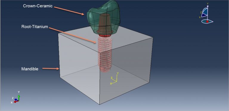
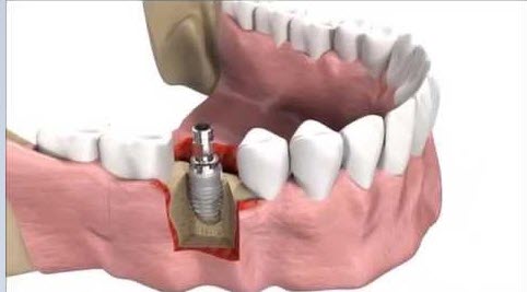
In this tutorial, the simulation of a dental implant interacting with the mandible bone under dynamic load in Abaqus is investigated. The crown, abutment, and mandible bone are modeled as three-dimensional parts. Dental implants, which are metal posts or frames surgically positioned into the jawbone beneath the gums, provide stable support for artificial teeth once they fuse with the jawbone. This secure fit prevents dentures and bridges mounted to implants from slipping or shifting in the mouth, offering a more natural feel compared to conventional bridges or dentures, particularly during eating and speaking.
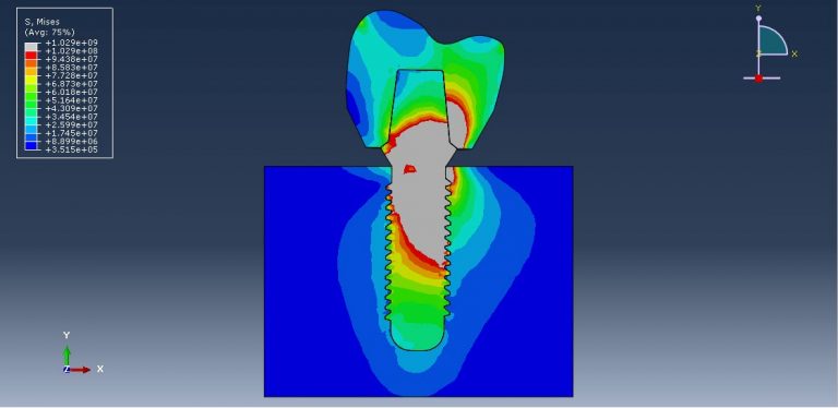
The crown is modeled using a ceramic material with elastic-plastic behavior and a ductile damage criterion. The root or abutment material is modeled with titanium, utilizing elastic-plastic properties and the Johnson-Cook damage model. The mandible bone is modeled as an elastic-plastic material. A dynamic explicit procedure is employed to handle the dynamic loading conditions. The general contact algorithm with defined contact properties models the interactions among all parts. Appropriate boundary conditions are applied to the mandible, and a concentrated force with smooth amplitude is applied to the crown. Due to the complexity of the model, a fine mesh is required.
During the analysis, the applied force induces stress in the assembled parts, and the critical zones can be identified from the model.
Workshop-8 Simulation of dental implant insertion
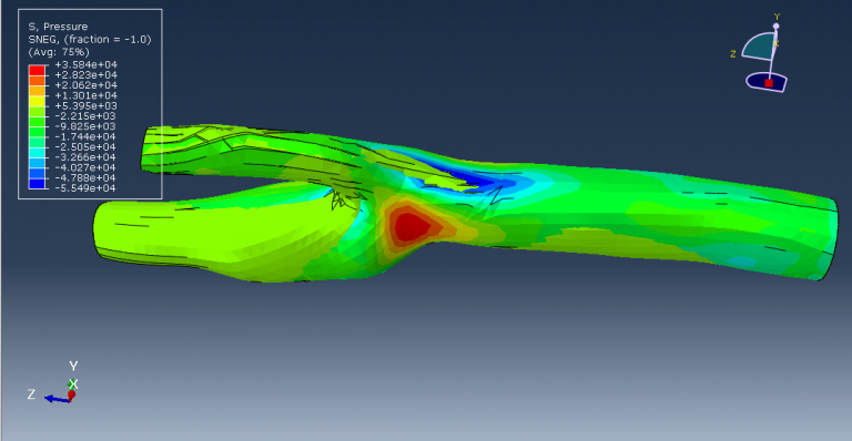
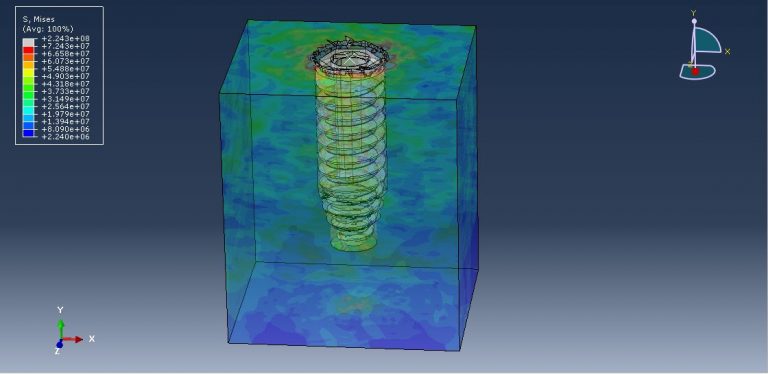
In this tutorial, the simulation of dental implant insertion in Abaqus is investigated. Successful osseointegration, which denotes the stability of an implant post-integration, depends on primary and secondary implant stability. Primary stability refers to the mechanical engagement of the implant immediately after insertion, while secondary stability results from long-term bone regeneration and remodeling around the implant. These two types of stability are interconnected, as inadequate primary stability is a leading cause of implant failure. The finite element method (FEM) is a widely used technique for analyzing the biomechanical behavior of bone-implant rehabilitation components and evaluating their mechanical interactions, which are challenging to study experimentally in vitro or in vivo. FEM allows researchers to apply various loading configurations and determine the displacement and stress levels experienced by the tooth, prosthesis, implant, and bone.
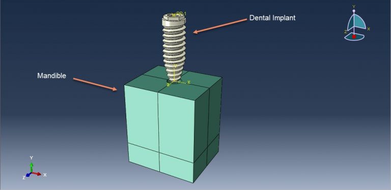
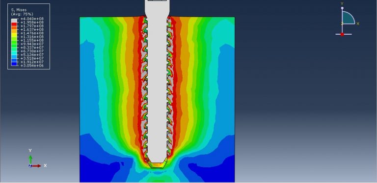
In this simulation, the implanted root is modeled as a three-dimensional part and imported into Abaqus due to its complexity. The implant is assumed to be a rigid body, while the mandible bone is modeled as a three-dimensional solid part. The implant root is made of titanium. The mandible bone material is modeled as an elastic material with Johnson-Cook plasticity and damage with evolution, which can predict damage and failure in the bone during insertion. The dynamic explicit step with a mass-scaling technique is appropriate for this analysis. The interaction is modeled as general contact, considering internal damage using the input file capability. The rigid body constraint is assigned to the implant part in the interaction section. The mandible part has a fixed boundary condition, and the implant part is subjected to axial displacement with amplitude and rotational velocity. A fine mesh is required to ensure good performance and accurate results.
After the simulation, all results such as stress, strain, damage, and pressure can be obtained.











tullio –
This package was really interesting! It showed the great capability of Abaqus. Thank you for posting the demo and explaining it very well.
ben –
You have done a great job! Do you accept custom packages or at least give companies some kind of assistance in their projects?
cox –
Hello, thank you for preparing this package. It was one of the most complete biomechanics trainings. Do you have any other package about this topic?
Grace –
I highly recommend the Bio-Mechanical Abaqus Simulation Full Package from CAE Assistant! The step-by-step tutorials and instructional videos are incredibly helpful and provide comprehensive content. I thoroughly enjoyed this package and am impressed with its quality. If you want to learn bio-mechanical simulation using Abaqus, definitely give this package a try!