Introduction to Earthquake Damping Solutions
In recent years, many structures have collapsed due to earthquakes, highlighting the need for effective earthquake damping strategies. Seismic loads, which are dynamic forces from earthquakes, cause free vibrations in buildings. This leads to deflections in all directions and increases the risk of failure in structural members. While components like dampers can dissipate some earthquake energy, structures in seismic zones must be designed to withstand these forces according to strict standards.
However, guidance on designing structures with advanced dampers, especially novel systems like the bypass viscous damper, is limited. Extensive experiments and simulations are necessary to close this gap. By quantifying the energy dissipation of these dampers and adjusting structural stiffness, we can better simulate their performance in steel and reinforced concrete frames.
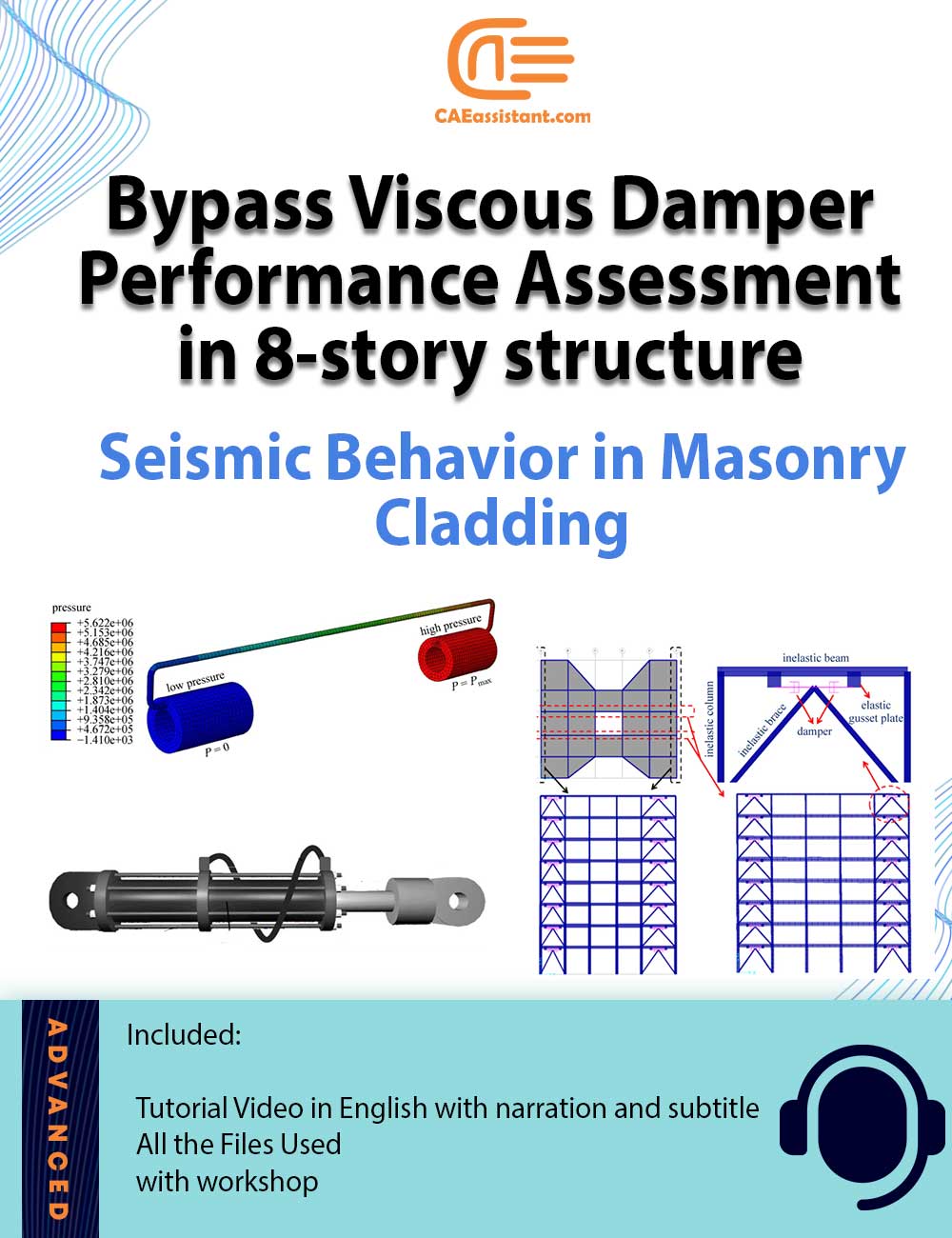
This tutorial package evaluates the dynamic behavior of a bypass viscous damper, which uses a flexible hose as an external orifice for fluid transfer. A simplified design procedure for incorporating these dampers is also proposed. To demonstrate their effectiveness in earthquake damping, we analyze an eight-story hospital with and without bypass dampers and compare it to a version with concentric braces.
Nonlinear time history analyses show that the hospital with viscous dampers experiences reduced structural demands and lower story accelerations, easing the strain on nonstructural components. Furthermore, the seismic performance of nonstructural masonry cladding is compared between the different hospital designs. This project will explore these methods in detail, with each covered in separate workshops.
By incorporating effective earthquake damping solutions, structures in seismic zones can achieve greater safety and resilience.
What is the developed bypass viscous damper?
The developed bypass viscous damper shares similarities with other viscous dampers but introduces a key innovation—a flexible, high-pressure hose serving as the external orifice. During dynamic excitations, it is well known that input energy is dissipated as heat. In traditional viscous dampers, this can cause the temperature of the damper oil to rise significantly, sometimes reaching up to 400°F. This increase in temperature highlights the importance of thermal compensation for ensuring effective earthquake damping.
In the bypass viscous damper, the external orifice acts as a thermal compensator, reducing the effects of viscous heating. Additionally, the damping coefficient and damping exponent can be adjusted by modifying various factors such as the length, diameter, and flexibility of the hose. This flexibility allows for fine-tuning the damper’s performance according to specific seismic requirements.
In this package, the dynamic behavior of the bypass viscous damper is thoroughly evaluated. By using the flexible hose as an external orifice, the fluid inside the damper is transferred from one side of the inner piston to the other. This design allows for precise adjustments to the viscosity coefficient through changes in the hose’s geometric dimensions. Moreover, the external orifice not only enhances control over damping characteristics but also serves as a thermal compensator, mitigating the heat generated during intense seismic activity.
This innovation in earthquake damping technology offers improved control over both thermal and dynamic behavior, ensuring better performance in structures exposed to seismic loads.
Investigating Seismic Damping in Structures with Bypass Viscous Dampers | CFD & Structural models
To evaluate the performance of the proposed bypass viscous damper, both CFD simulations using ABAQUS and experimental tests are employed. Two numerical methods are used: CFD in ABAQUS and a simplified Maxwell model in SAP 2000. These approaches help assess the effectiveness of the damper in providing seismic damping for structures. Based on experimental results, the CFD model, a numerical formula, and the simplified Maxwell model are developed and assessed, verifying the accuracy of the computational and numerical simulations.
In this package, we present a simplified design procedure for incorporating bypass viscous dampers into structures. This procedure is applied to an eight-story hospital, which is analyzed with bypass viscous dampers and compared to a version designed with concentric braces and another without dampers. Nonlinear time history analyses show that the hospital with bypass dampers experiences reduced structural inelastic demands and fewer story accelerations. This translates into lower demands on nonstructural elements, contributing to better seismic performance.
Additionally, the seismic behavior of nonstructural masonry cladding is compared in hospital structures both with and without dampers. The findings demonstrate the significant role that bypass viscous dampers play in enhancing seismic damping and improving the overall resilience of structures during earthquakes.
Method 1: CFD and Finite volume method (FVM) to Analyze a Seismic Damping System with Bypass Viscous Dampers
In this approach, CFD models are utilized to simulate the behavior of the bypass viscous damper, a critical component in a seismic damping system. The simulation focuses on the fluid parts of the damper using ABAQUS, while the solid components like the piston, cylinder, and hose walls are accounted for through a no-slip boundary condition at the fluid-solid interface. This ensures the effect of these solid parts on turbulent fluid flow is properly considered.
Various input velocities are applied to the model, and the pressure difference between the front and back of the piston is used to calculate the corresponding damper force. From this, the force-velocity curve of the damper can be estimated, as verified against experimental results. This comparison is crucial for validating the accuracy of the CFD model.
This package includes a simplified design procedure that outlines a step-by-step method for incorporating viscous dampers into buildings. By following this method, designers can effectively implement a seismic damping system that enhances the structure’s ability to dissipate seismic energy, improving its resilience during earthquakes.
Method 2: Simulation of the developed bypass viscous damper in structural design
Method 3: The effect of the developed bypass viscous damper on structural behavior and material
The structure of a hospital as a case study is considered to be designed with and without this viscous damper for evaluating the performance of this viscous damper in the specified structure; therefore, two same hospital structures are modeled with and without this viscous damper by using SAP2000, which details this method is described in this package. After analyzing these structures, one of the nonstructural masonry claddings at the 8th story, which is located in the same place in the two structures, is considered to evaluate the performance of the viscous damper on nonstructural masonry claddings; therefore, these walls are modeled and analyzed based on the exported load of SAP models in ABAQUS/Standard.
Workshop 1: Simulation of the performance of the bypass viscous damper by FVM
In this workshop, first, the simulation of the bypass viscous damper using the CDF model is presented. Using this model, an equation is presented that can represent the performance of the bypass viscous damper.
Workshop 2: Representing the performance of the bypass viscous damper in the structure
In this Workshop, a step-by-step simplified design procedure is proposed for designing buildings with viscous dampers. In order to attain a desired target damping ratio, the required total damping coefficient of linear viscous dampers can be estimated. An approach to specifying the optimal place for the bypass viscous damper is presented to the structural engineer and designer.


Reviews
There are no reviews yet