What are Optimization and Structural optimization?
Optimization is the process of making something as perfect and effective as possible. It is used in various fields and problem areas, such as engineering, finance, and communication networks. In engineering, optimization is crucial for improving efficiency, reducing costs, and enhancing safety.
In the context of structural optimization, the goal is to design or modify structures to meet specific performance criteria while minimizing or maximizing certain objectives. This involves finding the best configuration, shape, or material distribution to achieve desired outcomes, such as strength, weight reduction, cost reduction, or improved efficiency.
Structural optimization finds applications in civil engineering, aerospace engineering, mechanical engineering, and automotive design. It enables engineers to explore different design possibilities, enhance structural performance, save on material usage, and create more efficient and cost-effective designs.
Optimization simulation in Abaqus
Abaqus, a software used for structural optimization, offers four types of optimizations: Topology, Shape, Sizing, and Bead optimization. This training package focuses on explaining Shape optimization.
The terminology used in ABAQUS optimization
Here are some of the terminologies used in ABAQUS optimization:
Optimization task: An Optimization Task defines the type of optimization and carries all the necessary settings.
Design area: The Design Area refers to the region of the model that is modified during structural optimization.
Design responses: Design Responses are the inputs or goals of the optimization process.
Objective function: The Objective Function is a quantity that is to be maximized or minimized, which can be a single design response or a combination of responses.
Constraints: Constraints restrict the value of design responses.
Design variable: Design Variables are parameters that are modified during optimization.
Geometric restrictions: Geometric Restrictions are constraints applied directly to design variables, accounting for design and manufacturing limitations.
Optimization process: The Optimization Process iteratively searches for an optimized solution based on the defined objective functions and constraints.
Stop conditions: Stop Conditions specify when the optimization process should be terminated.
Lesson 1: What is Shape optimization?
In this lesson you will learn the concept of shape optimization, Abaqus algorithms for shape optimization, and the difference between the algorithms. Here are some of contents of this lesson:
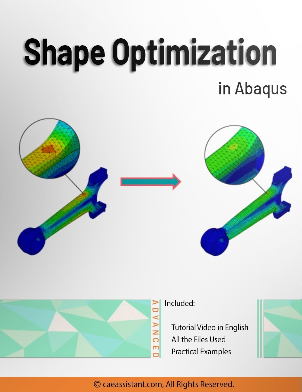
You use shape optimization at the end of the design process when the general layout of a component is fixed, and only minor changes are allowed by repositioning surface nodes in selected regions. Therefore, in shape optimization, the design variables are the displacements of the surface nodes (design nodes). A shape optimization starts with a finite element model that needs minor improvement or with the finite element model generated by a topology optimization.
In shape optimization, typically, the goal is to homogenize the stress on the surface of a component by adjusting the surface nodes. Thus, the minimization is achieved by homogenization. The design nodes have two possible movements: outward (growth), which causes the model to become larger or “bulkier” in shape, or inward (shrinkage), which causes the model to become smaller or “thinner” in shape.
The shape optimization is done in Abaqus by two algorithms, just like the topology optimization: the general (sensitivity-based) algorithm and the condition-based algorithm. The differences between these two algorithms, besides their coding structure for optimization, are in their Abaqus settings, and that’s what will be explained in this lesson.
Lesson 2: Shape Optimization setup in Abaqus
In this lesson, we will provide a detailed explanation of all the necessary settings required to apply Shape optimization in Abaqus. This includes a thorough explanation of the optimization task and design responses.
First, we must create an optimization task to determine which optimization we want to perform. After that, you must select the design area. After creating a task for the shape optimization, we must define the required design responses. Next, the Objective functions and Constraints suitable for each design response must be defined. Next, the Geometric restrictions of shape optimization must be set. As you know, Geometric restrictions are constraints that are applied directly to the design variables. Geometric restrictions allow you to model design limitations and manufacturing limitations. Stop conditions are examined after each design cycle and determine whether an optimization should end because the maximum number of design cycles has been reached or because the optimization has converged on an optimal solution. In other words, the stop conditions determine when an optimization process must end. There are two types of stop conditions: General stop conditions and local stop conditions. The General stop conditions are the same maximum number of design cycles we specify in the Job module for an optimization process. The local stop conditions are supported only by shape optimization and are rarely required.
Lesson 3: Shape Optimization process in Abaqus
In this lesson, first, you will learn how to create an optimization process for your model. To initiate an Optimization Process, navigate to the Job module and utilize the final tool located within the toolbox section. It’s like the Topology optimization and there is no difference in this matter.
After that, the post processing of shape optimization will be explained. Each of the optimization types has its own variables. The Shape optimization has three variables. The first one is a vector indicating the direction in which the nodes were moved during the shape optimization (Nodal displacement vector). Because of mesh smoothing and filtering, the vector may not be coincident with the node normal vector. The second one is the magnitude of the nodal displacement vector with a sign indicating the direction of the displacement; positive for growth and negative for shrinkage. And the third one is the value of the objective function at each node, for example, stress. You can see these variables in the Visualization module after combining the results.
It would be helpful to see Abaqus Documentation to understand how it would be hard to start an Abaqus simulation without any Abaqus tutorial. Also, be careful with the units of values you insert in Abaqus. Yes! Abaqus don’t have units but the values you enter must have consistent units. You can learn more about the system of units in Abaqus.







HeeJin –
I found this package on shape optimization in Abaqus to be extremely helpful. It breaks down the complex topic into manageable sections, providing clear explanations and practical examples. but I have some Question, could you please guide me how can I connect to expert?
Experts Of CAE Assistant Group –
You’re most welcome! It was a pleasure serving you, and I’m thrilled to hear that you’re pleased with the outcome. We appreciate your feedback and look forward to assisting you again in the future. You can send your question to [email protected] or connecting via online support or WhatsApp company