Simulation of an Ultrasonic Transducer (3D Ultrasonic Vibration Assisted Turning Tool)

 190.0

Since the invention of ultrasonic vibration assisted turning, this process has been widely considered and investigated. The reason for this consideration is the unique features of this process which include reducing machining forces, reducing wear and friction, increasing the tool life, creating periodic cutting conditions, increasing the machinability of difficult-to-cut material, increasing the surface quality, creating a hierarchical structure (micro-nano textures) on the surface and so on. Different methods have hitherto been used to apply ultrasonic vibration to the tip of the tool during the turning process. In this research, a unique horn has been designed and constructed to convert linear vibrations of piezoelectrics to three-dimensional vibrations (longitudinal vibrations along the z-axis, bending vibrations around the x-axis, and bending vibrations around the y-axis). The advantage of this ultrasonic machining tool compared with other similar tools is that in most other tools it is only possible to apply one-dimensional (linear) and two-dimensional (elliptical) vibrations, while this tool can create three-dimensional vibrations. Additionally, since the nature of the designed horn can lead to the creation of three-dimensional vibrations, there is no need for piezoelectric half-rings (which are stimulated by a 180-phase difference) to create bending vibrations around the x and y axes. Reduction of costs as well as the simplicity of applying three-dimensional vibrations in this new method can play an important role in industrializing the process of three-dimensional ultrasonic vibration assisted turning.

In this example, how to model all the components of an ultrasonic transducer and its modal and harmonic analysis are taught in full detail.

Expert

Included

.inps,video files, Fortran files (if available), Flowchart file (if available), Python files (if available), Pdf files (if available)

Tutorial video duration

35 minutes

language

No narration

Level

Package Type

Software version

Applicable to all versions

Subtitle

No subtitle

Add-on

The option's price will be set post-order, requiring negotiation with support for confirmation.

The option's price will be set post-order, requiring negotiation with support for confirmation.
Product price:  190.0
Total options:
Order total:
44 People watching this product now!

Frequently Bought Together

Ultrasonic transducer simulation + + Abaqus Course for beginners - FEM simulation tutorial - FEA simulation
Price for all three: Original price was: € 631.0.Current price is: € 473.2. Save  157.8
Description

1. Introduction| Abaqus Ultrasonic Transducer Simulation

In this research, a unique ultrasonic horn has been designed and constructed to convert linear vibrations of piezoelectrics to three-dimensional vibrations (longitudinal vibrations along the z-axis, bending vibrations around the x-axis, and bending vibrations around the y-axis). In this example, how to model all the components of an ultrasonic transducer and its modal and harmonic analysis are taught in full detail.

Ultrasonic Horn

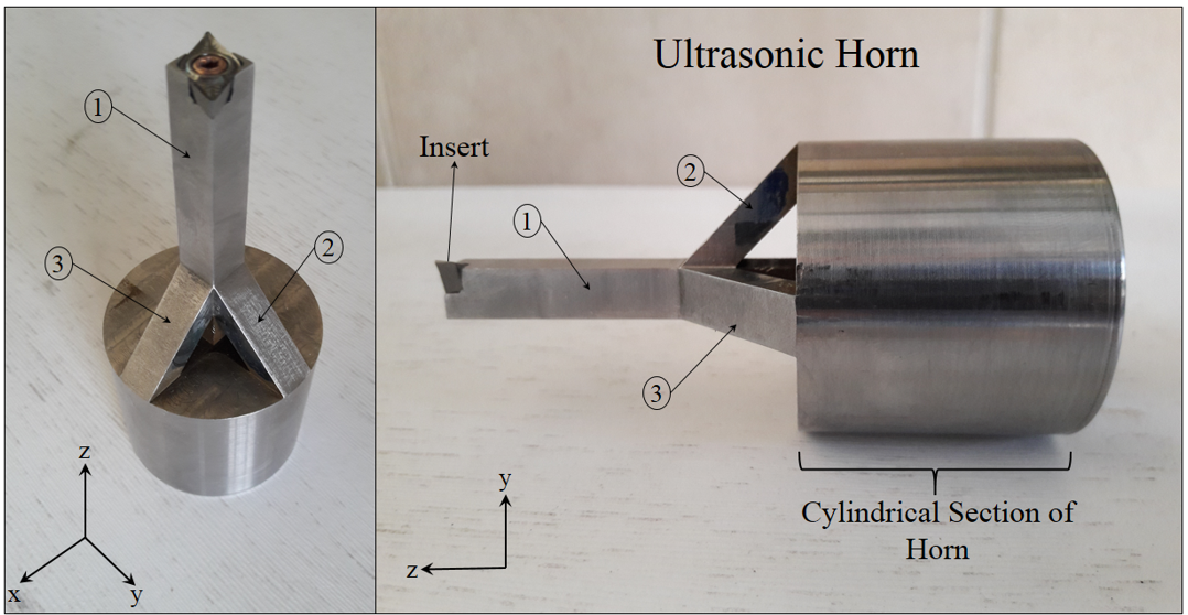
Figure 1: The innovative horn for transforming linear vibrations into 3D vibrations

1.1. What is the Ultrasonic Transducer?

An ultrasonic transducer is a device that converts electrical energy into sound waves at frequencies above the range of human hearing (ultrasound). They come in three types: transmitters (emitting ultrasound), receivers (detecting ultrasound), and transceivers (doing both).

1.2. What are the uses of ultrasonic transducers?

Ultrasonic transducers have a wide range of uses due to their ability to generate and sense high-frequency sound waves. Some common applications include:

  • Industrial cleaning: Ultrasonic waves can dislodge dirt and debris from delicate parts in a cleaning bath.
  • Medical imaging: Ultrasound technology uses transducers to create images of internal organs and tissues.
  • Non-destructive testing: Ultrasonic waves can be used to detect cracks and flaws in materials.
  • Sonar and navigation: Underwater, transducers emit and receive sound waves to determine distance and obstacles.

1.3. How to simulate an ultrasonic transducer with all its components?

Simulating an ultrasonic transducer with Abaqus software involves creating a digital model of all its components, including piezoelectric rings (which convert electrical signals to vibrations), backing parts (providing support), and a horn (concentrating the vibrations). Material properties for each component (steel, piezoelectrics) need to be defined within the software. The simulation can then apply a pre-load to mimic screw tightening, followed by modal analysis to find the resonant frequency and harmonic analysis to determine the vibration characteristics of the horn tip.

1.4. Why is numerical simulation of ultrasonic transducer important?

Numerical simulation with Abaqus allows engineers to virtually test and optimize the design of an ultrasonic transducer before building a physical prototype. This can save time and resources by identifying potential issues early in the design process. It allows for analyzing various configurations and materials without the need for real-world experimentation.

1.5. Is Abaqus applicable for simulating ultrasonic transducer overall assembly?

Abaqus is a powerful software suite well-suited for simulating the overall assembly of an ultrasonic transducer. It offers tools for defining material properties, setting up contact interactions between components, applying boundary conditions (like screw pre-load and voltage on piezoelectrics), and creating a mesh for analysis. Abaqus can then be used to extract results like stress distribution and vibration amplitude, providing valuable insights into the transducer’s performance.

2. Ultrasonic Transducer Simulation (PDF File)

This project shows you how to simulate the ultrasonic transducers in such a way that you can accurately predict the effect of all relevant parameters on the resonant frequency and horn tip vibration amplitude.

  • Modal and harmonic analyses of the entire ultrasonic transducer are performed.
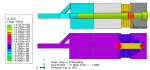
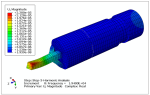
  • Compressive prestress in piezoelectric rings (S33), the resonant frequency of the transducer assembly, horn tip vibration amplitude (U), the diagram of resultant amplitude as a function of vibrational frequency, stress distribution field, etc., are the output results of this analysis.
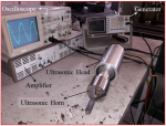
  • To verify this model, the simulation results and experimental results of resonance frequency and vibration amplitude of the transducer are compared.
  • The resonance frequency and vibration amplitude of the horn in the simulation are in good agreement with the experimental results.
  • This project is designed to enhance participants’ understanding of how to accurately simulate the ultrasonic transducers.

2.1. PROBLEM DESCRIPTION

In this research, a unique horn has been designed and constructed to convert linear vibrations of piezoelectrics to three-dimensional vibrations (longitudinal vibrations along the z-axis, bending vibrations around the x-axis, and bending vibrations around the y-axis). In Figure 2, the general assembly view of the transducer (including four complete piezoelectric rings, backing and matching parts, Allen screw, and horn), is shown. In this example, the vibration analysis of the transducer (including modal analysis and harmonic analysis) has been carried out in order to determine the resonance frequency, vibration modes, the size of the vibration amplitude, how the ultrasonic vibrations propagate in the horn, and also to find the node points for clamping the transducer and horn.

Ultrasonic transducer

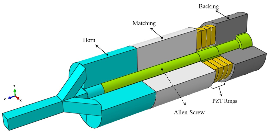
Figure 2: Cutting view of the ultrasonic transducer overall assembly

2.2. PROJECT PROCEDURES

  1. Setting up the software environment and choosing Abaqus units
  2. Creating ultrasonic transducer parts (ultrasonic transducer design)
  3. Defining the properties of steel 1.6582 (BOZ) and PZT and creating their relevant sections
  4. Making an instance of the model in the Assembly module
  5. Creating 3 steps of transducer analysis, choosing the outputs of each step
  • Preloading step to simulate the initial stress conditions caused by bolt tightening (applying initial compressive stress to the piezoelectrics)
  • Modal analysis to determine the resonant frequency of the transducer
  • Harmonic analysis to determine the vibration amplitude of the horn tip
  1. Defining the electro-mechanical interactions
  2. Determining the loading and boundary conditions, etc.
  3. Generating elements and assigning element types
  4. Submitting the job
  5. Viewing the results
  • What is the Ultrasonic Transducer?
  • What are the uses of ultrasonic transducers?
  • How to simulate an ultrasonic transducer with all its components?
  • Why is numerical simulation of ultrasonic transducer important?
  • Is Abaqus applicable for simulating ultrasonic transducer overall assembly?
  • PROBLEM DESCRIPTION
  • PROJECT PROCEDURES
  • Executing Project Procedures

2.3. Executing Project Procedures

  1. Setting up the software environment
  2. Geometry:

This example includes lagrangian parts of ultrasonic transducer components (piezoelectric rings, backing and matching parts, Allen screw and horn).

  1. Material Properties:

The materials properties used in this example are presented in an Excel file named “Material Properties”. How to calculate the properties of piezoelectrics is fully explained in the “Theoretical and Base Relations” section.

  1.  Assemble the parts in the Assembly module:

Watch the video for more detail.

  1. Steps:

In modeling the transducer of this example, the following three steps are considered:

  • Preloading step for applying initial compressive stress to the piezoelectrics.
  • Modal analysis to determine the resonant frequency of the transducer.
  • Harmonic analysis to determine the vibration amplitude of the horn tip.
  1. Interactions:

A friction interaction for the whole model ( and normal hard contact) is considered (except for two cases: 1- the contact between the screw and the internal surface of the backing part 2- the contact between the screw and the internal surfaces of the matching part and horn). Regarding the contact between the screw and the inner surface of the backing part, frictionless tangential interaction and normal interaction of “Hard Contact” type were used in order to prevent parts from penetrating each other. The outer surface of the screw and the inner surfaces of the matching part and horn were also completely connected through the tie constraint so that there is no relative movement between these surfaces.

  1. Boundary Conditions:

Applying a preload of 35,000 newtons to the screw and a voltage difference of 2,200 volts to both ends of piezoelectrics.

  1. Meshing:

Partitioning of transducer components for better meshing, generating elements and assigning element types.

  • In simulation of the transducer, the modeling of the copper rings between the piezoelectrics was neglected. Because for the correct meshing of these rings and observing the aspect ratio, very small elements should be used, which, despite increasing the cost of calculations and analysis time, do not have much effect on the accuracy of the analysis.

The meshing operation was also performed using 20-node quadratic brick elements with reduced-integration (C3D20R). Because in the quadratic elements with reduced integration, even when the model is subjected to complex stresses and is meshed with coarse elements; “Locking Phenomena” do not occur. Therefore, these types of elements are the best choice for stress-displacement analyzes (except for analyzes in which large deformations occur).

  1. Submitting the job:

In the job module, after creating the job, you should submit the job.

  1. Guidance on how to extract the results:

In the video file, the process of extracting the results is shown in full detail.

3. Workshop (Video file): A step-by-step guide on the simulation of ultrasonic transducer

The workshop provides a full step-by-step guide through a video to simplify the simulation of the ultrasonic transducer overall assembly.

In the video, we used three steps (“Static, General”, “Frequency” and “Steady-state” steps) and defined all the necessary requested outputs for the ultrasonic transducer simulation. Following this, we defined the interactions between the ultrasonic transducer components in a reasonably simple way. Then we applied the initial and boundary conditions, such as initial stress and a voltage difference to both ends of piezoelectrics. The meshing operation was also performed using 20-node quadratic brick elements with reduced-integration (C3D20R). Because in the quadratic elements with reduced integration, even when the model is subjected to complex stresses and is meshed with coarse elements; “Locking Phenomena” does not occur. Therefore, these types of elements are the best choice for stress-displacement analyses (except for analyses in which large deformations occur). Finally, we show how to submit a job and extract the results in full detail.

It would be helpful to see Abaqus Documentation to understand how it would be hard to start an Abaqus simulation without any Abaqus tutorial. One note, when you are simulating in Abaqus, be careful with the units of values you insert in Abaqus. Yes! Abaqus don’t have units but the values you enter must have consistent units. You can learn more about the system of units in Abaqus.

Shipping and Delivery

All the package includes Quality assurance of training packages. According to this guarantee, you will be given another package if you are not satisfied with the training, or your money is returned. Get more information in terms and conditions of the CAE Assistant.
All packages include lifelong support, 24/7 support, and updates will always be sent to you when the package is updated with a one-time purchase. Get more information in terms and conditions of the CAE Assistant.

Notice: If you have any question or problem you can contact us.
Ways to contact us: WhatsApp/Online Support/Support@CAEassistant.com/ contact form.
Projects: Need help with your project? You can get free consultation from us here.

  • Online payment: with MasterCard, VisaCard and etc.
  • Offline payment: In this payment method, you should pay via PayPal and send your payment receipt as an attached file in the offline payment form.
  • via download link After purchase, a download link will be sent to you a zip file included training videos, documents and software files.
  • Send us your machine ID

To access tutorial video run the .exe file on your personal pc and send the generated code to shop@caeassistat.com and wait for your personal code, which is usable only for that pc, up to 24 hours from CAE Assistant support.

Here you can see the purchase process of packages: Track Order

Features

Abaqus tutorial video
Lecture notes
Abaqus workshop files
Contains all required files
Certification
Works for all Abaqus versions
Safe payment
money-back guarantee
Free 24/7 online mentoring
Access for life
updated content
Time-Saving Short But Full
Premium Corporate and Academic Clients
Prepared by High-Level Researchers
Fortran Abaqus subroutines
All payment method

Reviews

There are no reviews yet

Be the first to review “Simulation of an Ultrasonic Transducer (3D Ultrasonic Vibration Assisted Turning Tool)”
SKU: Sajjadi62024-3 Category: Tag: