Showing all 5 results

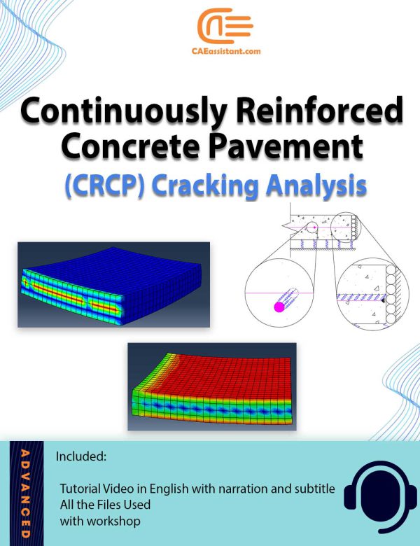
Continuously Reinforced Concrete Pavement (CRCP) Cracking Analysis

 210.0

The increasing adoption of continuously reinforced concrete pavement (CRCP) in highway pavement design is driven by its demonstrated superior performance. Critical to evaluating the long-term effectiveness of CRCP is the understanding of early-age cracks (CRCP crack analysis), which has garnered significant interest from highway departments. This Abaqus Continuously reinforced concrete pavement modeling project aims to establish precise design parameters for CRCP and analyze the formation of crack patterns. By accounting for stress factors such as environmental conditions and CRCP shrinkage modeling, the project offers valuable insights into predicting the likelihood of crack initiation and propagation within the concrete slab. These insights are instrumental in enhancing the durability and performance of CRCP structures, thus advancing the efficiency and effectiveness of highway infrastructure.

Laser forming simulation tutorial in Abaqus

 120.0
The laser forming process is performed by applying thermal stresses to the workpiece surface by heating the surface with a laser beam. These internal stresses induce plastic strains in the part resulting in local elastic-plastic deformation (Laser-induced plastic deformation). In this laser forming simulation tutorial the DFLUX subroutine is used to apply heat flux (Gaussian heat distribution) dependent on location and time in finite element simulation. For example, the linear heating processes of laser forming and welding (with a slight simplification) can be simulated by this subroutine. In the linear heating process, by applying heat flux to the surface of a sheet, a thermal gradient is created in its thickness. This thermal gradient causes permanent deformation of the sheet. To simulate the laser forming process, it is necessary to apply a time and location-dependent heat flux to the sheet. In this type of loading, a heat flux is applied on the plate, which is defined using the DFLUX subroutine, including the laser power, movement speed, beam diameter, absorption coefficient, and laser movement path according to the designed experiments (Laser forming process parameters). To verify this Abaqus laser forming simulation, the simulation results and experimental results of sheet deformation (U) are compared. The displacement of the sheet in the simulation is in good agreement with the experimental results.

Friction Stir Welding simulation Tutorial | FSW Advanced level

 100.0
Friction stir welding (FSW) involves complex material flow and plastic deformation. Welding parameters, tool geometry, etc., have important effects on the material flow pattern, heat distribution, and eventually on the structural evolution of the material. In an Abaqus friction stir welding example, the rotational movement of the tool and its friction in contact with the workpiece causes heat generation, loss of strength, and an increase in material ductility around the tool. The feeding movement of the tool causes the material to transfer from the front of the tool to the back of it, and eventually leads to a join. Therefore, heat plays an important role in this process, and parameters such as rotational speed, tool feeding speed, tool geometry, and others, all somehow have a significant impact on controlling the amount of incoming heat, the disturbance and flow pattern of the material, the evolution of the microstructure, and the quality of the resulted weld. This friction stir welding example simulation tutorial shows you how to simulate the Abaqus FSW simulation process in such a way that you can accurately predict the effect of all relevant parameters on the process. In most of the implemented projects, welding mud, and welding defects (welding overfills and overlaps, weld gaps) are not visible and predictable; however, in this simulation, these cases are visible. This project is designed to enhance participants' understanding of how to accurately simulate the FSW process to see the weld's general appearance.

Airfoil simulation with different angles of Attack | Ansys fluent

 220.0
Airfoils are a vital and important part of many industrial units. For example, in many kinds of rotary equipment such as gas turbines and wind turbines or compressors, airfoils play a vital role. Another usage of airfoils is in the aviation industry, which they used in airplane wings. The crucial parameters that are important in airfoils are the drag and lift forces or drag and lift coefficients. By using these parameters, we can design better airfoils to achieve greater lift coefficients and lesser drag coefficients. With this package, you learn how to design, mesh, and simulate an airfoil. Also, you learn how to link MATLAB to Ansys Fluent to change the geometrical constraints and boundary conditions automatically. You can use this method for your own optimization.

Sloshing Simulation in Cylindrical Water Storage Tanks: An Abaqus Modeling Framework

 120.0
Liquid storage tanks have many applications in water supply systems and industrial environments. However, seismic damages to these tanks present significant challenges. One of the well-known damages observed in tanks during earthquakes is roof fracture caused by liquid sloshing. Sloshing is a phenomenon that liquid surface moves during seismic events. In this project, we used ABAQUS for the sloshing simulation in ground-supported cylindrical tanks. The tank experiences the acceleration of the El-Centro earthquake. The Abaqus sloshing simulation involves the calculation of Rayleigh damping factors and natural frequencies, employing the ALE meshing technique, and incorporating hourglass controls in Abaqus. We have suggested two ways for the tank sloshing simulation: one involves assigning a low viscosity to the water, and the other is applying Rayleigh damping factors with the assumption of an inviscid fluid. For verification, we modeled a water tank and compared the results with those obtained in the following paper: “Parametric study on the dynamic behavior of cylindrical ground-supported tanks”