


 in Abaqus-1")
 in Abaqus-2")
 in Abaqus-3")


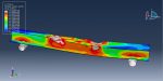


Workshop-1: cyclic loading simulation in steel beam-column structure reinforced with CFRP
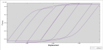
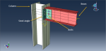
This tutorial explores the simulation of cyclic loading on a steel beam-column structure reinforced with CFRP in Abaqus. The steel beam and column are modeled as 3D shell parts, while the CFRP plates are modeled as planar shell parts. To simulate the behavior of steel under cyclic loading, the combined plasticity model is used, allowing for accurate prediction of material behavior during each cycle. For the CFRP material, engineering constants elasticity with Hashin’s damage criterion is applied.
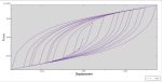
The analysis employs a general static step with adjustments to the convergence model. Perfect contact is assumed between the steel beam, column, and CFRP sheets. Fixed boundary conditions are applied at the top and bottom of the steel column, while displacement with an amplitude (based on a loading protocol) is applied to the steel beam’s end. A fine mesh ensures high accuracy in the results. After running the simulation, results such as stress, strain, displacement, and the hysteresis diagram can be obtained.
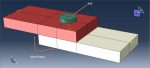
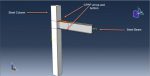
Workshop-3: Shear failure analysis of structure with bolt connection
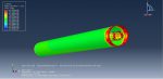
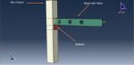
This tutorial focuses on simulating the shear failure of two steel plates connected by bolts in Abaqus. The steel plates and bolts, modeled as 3D solid parts, utilize an elastic-plastic material model. To predict damage and failure, both ductile and shear damage criteria are applied. The ductile criterion predicts damage onset due to void nucleation, growth, and coalescence, while the shear criterion addresses damage caused by shear band localization.
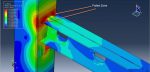
A dynamic explicit step is used to simulate the dynamic load applied as tension to the upper plate. Surface-to-surface contact with defined contact properties is set for all interaction domains. Fixed boundary conditions are applied to the bottom plate, and a smooth displacement amplitude is applied to the upper plate. To ensure accurate results, partitions are created for each bolt, and a fine, appropriate mesh is used to capture the correct failure mode and shape.
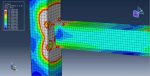
After the simulation, results such as stress, strain, damage, and failure patterns can be obtained. Under the applied load, the upper plate experiences complete damage and failure.
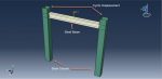
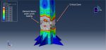
Workshop-4: Damage analysis of steel beam-column structure in cyclic loading
This tutorial focuses on simulating cyclic loading and damage investigation in a steel beam-column structure using Abaqus. The beam and columns are modeled as 3D shell parts. To simulate the steel behavior under cyclic loading, elastic-isotropic plasticity coupled with a ductile damage criterion is used for better damage prediction. While kinematic or combined plasticity models can be applied, isotropic plasticity paired with ductile damage provides more accurate results.
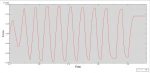
The analysis employs a general static step, with modifications to the convergence model to prevent early non-convergence issues. Perfect contact is assumed between the beam and columns, and the general contact algorithm is used to address any interference during the simulation. Fixed boundary conditions are applied to the column bases, and a cyclic displacement protocol is assigned as an amplitude for the columns. A fine mesh is critical for accurate results.
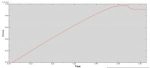
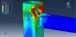
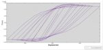
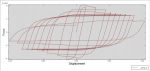
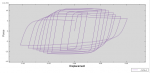
After running the simulation, results such as stress, strain, damage, failure patterns, and the force-displacement diagram can be obtained.
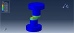
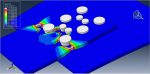
Workshop-5: Dynamic and failure analysis of bolt in steel plates joint
This tutorial examines the simulation of dynamic bolt failure in a bolt and steel plates joint using Abaqus. Both the upper and bottom steel plates, as well as the bolts, are modeled as 3D solid parts. Two primary mechanisms are considered for the fracture of ductile metals: ductile fracture caused by void nucleation, growth, and coalescence, and shear fracture resulting from shear band localization. Corresponding ductile and shear damage criteria are applied to predict the onset of damage during the simulation.
The dynamic explicit step, combined with a mass-scaling technique, is used to model the dynamic failure of the bolts. Surface-to-surface interaction is defined with properties like friction to account for contact behavior. Fixed boundary conditions are applied to both sides of the bedplate, while a smooth displacement amplitude is used to apply load to the upper steel plate. A fine mesh is essential for accuracy, and multiple partitions are created to achieve proper meshing.
After the simulation, results such as stress, strain, damage, failure, and displacement can be analyzed.
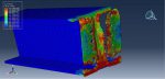
Workshop-6: Failure Simulation of steel bolted double angle connections in dynamic loading
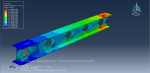
This tutorial focuses on the simulation of steel bolted double-angle connections under dynamic loading in Abaqus, with a focus on failure analysis. The beam, column, and bolts are all modeled as 3D solid parts. Connections play a vital role in maintaining the stability of steel structures by ensuring continuity of load paths between elements. All parts use grade 14 steel with an elastic-plastic material model. The ductile damage criterion is applied to predict damage and failure in the bolts and beam, allowing for damage observation after the simulation.
The dynamic explicit step is used for this analysis, along with a mass-scaling technique to reduce simulation time and stabilize the model. Surface-to-surface contact is defined with specific contact properties, and rough contact is applied to the bolt connections. Fixed boundary conditions are applied to both ends of the column, while displacement is applied to the beam’s end. Fine meshing is critical, especially in contact zones, and partitions are used to ensure high mesh quality.
After the simulation, results such as stress, strain, damage, and failure can be obtained and analyzed.
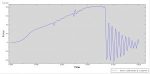
Workshop-7: Implicit damage analysis of steel beam structure in cyclic loading
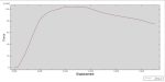
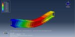
This tutorial explores the simulation of steel beam damage under cyclic loading in Abaqus Standard. Under cyclic loading, such as earthquake ground motions, local buckling occurs in the compression flange, disappearing and reappearing in subsequent cycles.
The beam is modeled as a 3D shell part, using a linear elastic, isotropic plasticity material model with a damage parameter to analyze damage distribution. A general static step is employed for this analysis, and the cyclic load is applied as a protocol to the beam’s tip. Fine mesh quality is essential to improve simulation accuracy.
During the simulation, stress, strain, and damage distribution on the beam are observed, providing valuable insights into its behavior under cyclic loading.
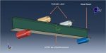
Workshop 8: Finite element simulation of composite joints in beams and steel–concrete
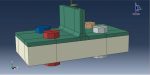
This tutorial investigates the numerical simulation of steel-concrete joints and composite beams. The model includes a concrete slab, steel sheet, steel beams, and rigid bodies. The Concrete Damage Plasticity (CPD) material model is used for the concrete, while an elastic-plastic model is applied to the steel. A dynamic explicit step with smooth amplitude is used to apply a smooth load.
Surface-to-surface contact is defined for the interactions between the rigid bodies and the concrete slabs, while perfect contact is assumed between the steel sheet and concrete. Beam elements are used to model the joint between the steel beam and sheet, which becomes a critical point when the stress reaches its peak. Boundary conditions are applied to the rigid bodies, and a high-quality mesh is necessary to ensure accurate results.
After running the simulation, results such as maximum stress, strain, and tensile/compressive damage can be obtained.
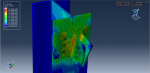
Workshop 9: steel-concrete composite column analysis in different loading types (vertical and horizontal loading)
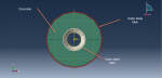
This tutorial explores the simulation of steel-concrete composite columns under vertical and horizontal loads in Abaqus. Steel-concrete composite columns are advanced composite structures widely used for their high load-bearing capacity, efficient material usage, high stiffness, ductility, and large energy absorption capabilities. By combining reinforced concrete (RC) and structural steel, these columns offer several advantages over traditional reinforced concrete and steel members, such as fire resistance for the steel and preventing buckling. However, SRC columns require both longitudinal and transverse reinforcement to prevent concrete spalling when subjected to axial loads, fire, or earthquakes.
In the model, the concrete column and steel beam core are represented as 3D parts, with the bar modeled as a wire and the pusher plate as a rigid body. An elastic-plastic material model with a ductile damage criterion is used for the steel, while the Concrete Damage Plasticity (CDP) model is applied to the concrete column. Both general static and dynamic explicit procedures are used separately, and the results are compared at the end of the simulations. Perfect contact is assumed between the concrete and steel beam, with the bars embedded in the concrete. A vertical concentrated force is applied to the top surface of the column, and a pressure load is applied to the side surface of the concrete.
After completing both static and dynamic simulations, results such as stress, strain, damage, displacement, and the force diagram can be obtained.
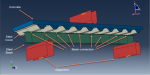
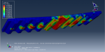
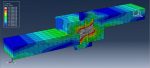
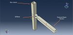
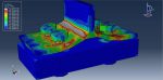
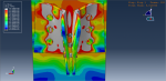
Workshop 10: Damage analysis of steel column with stiffeners in cyclic loading
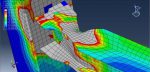
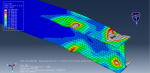
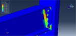
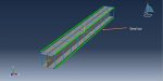
This tutorial investigates the simulation of cyclic loading on a steel column with stiffeners in Abaqus, with a focus on damage analysis. The box column is modeled as a 3D shell part, and the stiffeners are modeled as a planar shell part. The stiffeners are placed at the column’s end, acting as a weld zone to strengthen it. They are designed to shift the damage zone from the column’s end to a different location. While kinematic or combined plasticity models are typically used to capture cyclic behavior due to their variable yield surfaces, this simulation focuses on identifying the damage and failure locations, so isotropic plasticity with a ductile damage criterion is used instead. The ductile damage criterion helps predict the damage zone under cyclic loading.
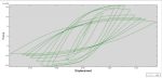
A general static step is used for the analysis. The end of the column and the bottom edges of the stiffeners are treated as a weld zone, applying fixed boundary conditions. A cyclic loading protocol is used to define the load amplitude. A fine mesh is essential to improve result accuracy. The results show how the failure or damage zone shifts from the column’s end to a higher position due to the stiffeners’ effect. All results, including stress, strain, and damage, can be obtained.


Reviews
Clear filtersThere are no reviews yet.