


1- Introduction to Abaqus Perzyna simulation using UMAT subroutine
This tutorial uses the UMAT subroutines to simulate the behavior of viscoplastic materials with the Perzyna viscoplastic rheological model. That is to say, the geometric models used in this study are a square and a cube under tension or torsion.
Viscoplasticity is a continuum mechanics theory that describes the time-dependent, irreversible (inelastic) strains solids, especially metals, solid polymers, and elastomers, experience when subjected to loading and deformation. Consequently, the viscoplasticity theory provides the most precise material model for estimating the mechanical behavior of all polymers.
In this regard, the primary goals of this study include the development and implementation of precise 2D and 3D models of viscoplasticity, and the integration of viscoplastic properties into the analysis, which can improve the prediction of viscoplasticity response under different boundary and loading conditions.
This tutorial discusses the Perzyna viscoplastic model. Most importantly, after explaining the viscoplasticity theory and detailing this model, it presents the related subroutines.
2- Viscoplasticity Abaqus Simulation Using UMAT Subroutine | Perzyna Viscoplastic Model (PDF File)
This project, after teaching the basic fundamentals of material rheological modeling, presents the accurate 2D and 3D mechanical responses of viscoplastic materials using the Perzyna viscoplastic model. That is to say, the Viscoplasticity Abaqus implementation is done with UMAT subroutines for the Abaqus standard solver.
2-1- Problem Description
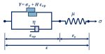
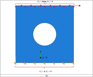
Geometry: The examples include the Lagrangian parts that are subjected to tension or torsion. To clarify, the schematic designs of the parts are shown in Figure 1. Above all, the material properties used in these examples are presented in an Excel file named “Material Properties”. That is to say, these properties are imported into the UMAT subroutines.
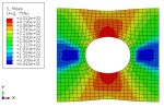
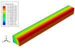
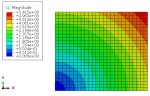
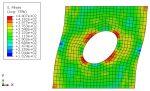
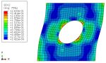
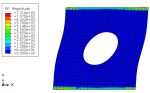
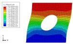
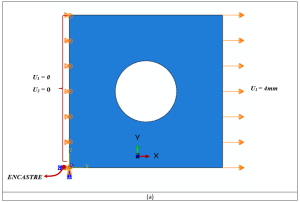
For the tensile problems, the right surface of the parts is pulled using the displacement boundary conditions, and some degrees of freedom of the left surface are restrained, as illustrated in Figure 2.a. Moreover, for the torsion problems, the upper surface of the parts is pulled using the displacement boundary conditions, and some degrees of freedom of the left surface are restrained, as illustrated in Figure 2.b.
2-2- Project Procedures
- Setting up the software environment and choosing Abaqus units;
- Creating the part;
- Defining the material properties and creating its relevant section;
- Making an instance of the model in the Assembly module;
- Creating two non-linear “Static, General” steps for loading and unloading analyses;
- Determining the loading and boundary conditions, etc.;
- Generating elements and assigning element types;
- Preparing the “Perzyna_3D_PlaneStrain” and “Perzyna_2D_PlaneStress” subroutines;
- Creating the jobs and calling the relevant UMAT subroutines for the jobs;
- Submitting the jobs;
- Viewing the results.
2-3- Executing Project Procedures
- Setting up the software environment
Geometry:
The examples include the Lagrangian parts subjected to tension or torsion. To clarify, figure 1 shows the schematic designs of the parts.
Material Properties:
We present the material properties used in this example in an Excel file named ‘Material Properties’. That is to say, we import these properties into the UMAT subroutine.
Steps:
The Analysis procedure for these examples would be the non-linear “Static, General” for the “Perzyna_3D_PlaneStrain” and “Perzyna_2D_PlaneStress” subroutines.
Note: see the attached files (Abaqus model and the UMAT subroutines) to understand the modeling.
Boundary Conditions:
Figures 2a and b show the boundary conditions for the tension and torsion problems, respectively.
Meshing:
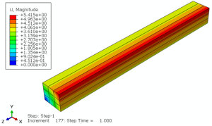
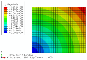
We performed the meshing operation using 8-node linear brick elements with ‘Distortion control’ (C3D8) for 3D models, and 4-node bilinear plane strain quadrilaterals (CPE4) and 4-node bilinear plane stress quadrilaterals (CPS4) for 2D models.
- Preparing the subroutines
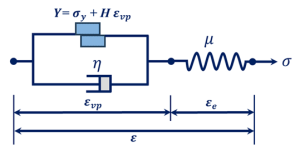
We explain all basic concepts of the rheological modeling of materials, especially the Perzyna viscoplastic model, in detail in the section ‘Theoretical and Base Relations’. Certainly, study this section carefully to understand “Perzyna_3D_PlaneStrain” and “Perzyna_2D_PlaneStress” subroutines.
- Creating the jobs and calling the UMAT subroutines
- Submitting the jobs
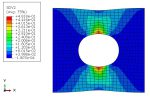
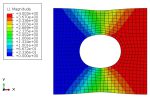
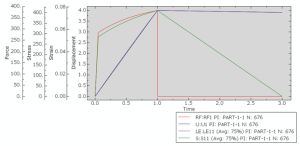
- Guidance on how to extract the results
The video file shows the process of extracting the results in full detail.
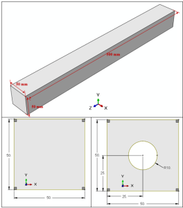
Figure 1: The schematic designs of the parts

Reviews
Clear filtersThere are no reviews yet.