


Introduction
In finite element analysis, a mesh refers to the discretization of a continuous domain into a collection of smaller, finite-sized elements. These elements are typically simple geometric shapes such as lines in 1D, triangles, and quadrilaterals in 2D, and tetrahedra and hexahedra in 3D. The mesh is created by dividing the domain into these elements and connecting them together at their shared vertices or edges.
Meshing is a crucial step in the finite element method as it determines the accuracy and reliability of the numerical solution. Here are some key points highlighting the importance of meshing in finite element analysis:
- Accuracy: The accuracy of the FEM solution heavily depends on the quality of the mesh. A well-refined mesh with appropriate element sizes can capture the behavior of the analyzed structure or system more accurately. On the other hand, a coarse mesh may lead to inaccurate results and may not capture the details of the problem accurately.
- Convergence: The convergence of the FEM solution is directly related to the mesh quality. A well-refined mesh ensures faster convergence of the solution, meaning that the solution approaches the true solution as the mesh is refined. A poorly refined mesh may result in slow convergence or even non-convergence of the solution.
- Solution stability: A well-structured and properly refined mesh helps in achieving solution stability. A stable solution is essential to obtain reliable results and avoid numerical instabilities or oscillations in the solution.
- Computational efficiency: The computational cost of the FEM analysis is directly related to the number of elements in the mesh. A well-optimized mesh with an appropriate number of elements can significantly reduce the computational time and resources required for the analysis.
- Boundary representation: The mesh provides a representation of the boundaries and interfaces of the analyzed system. The accuracy and quality of the mesh play a crucial role in accurately representing the boundaries and interfaces, which are essential for applying appropriate boundary conditions and capturing the behavior of the system accurately.
- Adaptivity: Mesh adaptivity allows for refining or coarsening the mesh in specific regions of interest based on the solution requirements. This adaptivity helps in focusing computational resources on critical areas and improving the accuracy of the solution without increasing the overall computational cost.
According to the stated mesh importance reasons, an efficient mesh can ensure that the analysis results are accurate, converged, computationally efficient, etc. For this purpose, a comprehensive knowledge of different meshes and techniques to mesh parts with suitable types of mesh is required.
This package introduces different meshing techniques in Abaqus through the following chapters:
“Mesh Importance in Finite Element”
In this chapter, mesh definition in finite element analysis is determined clearly and different mesh types for different solution spaces including 1D, 2D, and 3D are introduced. Knowing these different types of meshes is essential for further meshing process in Abaqus. The mesh convergency as a key factor to producing stable accurate results through an example is investigated.
“Mesh Module in Abaqus”
In this chapter, initially, the mesh module capabilities in Abaqus are mentioned. Then, the meshing process steps are determined which are:
- Assign mesh attribute and set mesh control
- Generating the mesh
- Refining the mesh
- Optimizing the mesh
- Verifying the mesh
Each of these steps is also explained in detail. Two meshing methodologies are also explained: Top-down and bottom-up. Top-down meshing relies on the geometry of a part to define the outer bounds of the mesh while Bottom-up meshing uses the part geometry as a guideline for the outer bounds of the mesh, but the mesh is not required to conform to the geometry. Different mesh techniques associated with these methodologies are then explained including Free, Structured, and Swept. Various characteristics for each meshing technique are completely declared which you need to know in order to make a part meshable with each technique.
“Advanced Meshing Techniques”
In this chapter, the mesh compatibility and its restrictions are explained first. Mesh compatibility means that the element faces or element edges of the meshes of adjacent part instances share the same nodes and have the same topology at the common interface. Then, the different steps to create a compatible mesh in solid and shell parts are determined.
Native and orphan meshes are also explained in this chapter. A mesh generated for a geometric part in Abaqus/CAE will maintain its association with the parent geometry is called a native mesh. You can import an existing mesh from Abaqus input (.inp) file, Abaqus output database (.odb) file, Nastran bulk data (.bdf) file, ANSYS input (.cdb) file, STL file (via plug-in). The imported mesh is called an orphan mesh because it has no associated parent geometry. You can also create a mesh part, a part with orphan mesh, from the part you have meshed with native mesh in Abaqus. A mesh part contains no feature information and is defined by a collection of nodes, elements, surfaces, and sets.
“Edit Mesh Toolset”
In this chapter, the Edit Mesh Toolset in Abaqus is introduced. This toolset provides the following tools in order to edit the generated mesh:
- “Manipulating nodes”
- “Manipulating elements”
- “Manipulating the mesh”
- “Refining the mesh”
Each of the mentioned tools has several options which help you to edit your mesh and improve mesh quality, which are explained in detail in this chapter.
“Verify Mesh”
In the last chapter, the final step of the meshing process which is ‘Mesh Verification’ is discussed. Upon completion of a meshing operation, Abaqus highlights any bad elements in the mesh. Abaqus also provides a set of tools in the Mesh module that allow you to verify the quality of your mesh and obtain information about the nodes and elements in the mesh. You can use these tools to isolate regions where the mesh quality is poor and to guide you if you need to refine your mesh.
Different mesh verification checks including shape metrics, size metrics, and analysis checks with the associated failure criteria are well-defined.
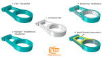
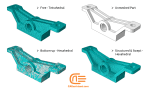
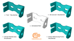
“Workshop 1: Exploring Meshing Techniques”
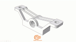
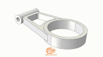
In this workshop, we have tried to implement all the points mentioned in this tutorial by meshing three different parts. Each one of these parts is meshed with different methodologies and techniques in order to be able to understand the difference between these methodologies and techniques. Also, different topics such as editing mesh, mesh verification, creating mesh parts, etc. are also implemented through these examples.
After viewing this workshop, you will have a great ability to know the differences between different meshing techniques and meshing various parts in the most efficient way in the Abaqus software.
It would be helpful to see Abaqus Documentation to understand how it would be hard to start an Abaqus simulation without any Abaqus tutorial. Moreover, if you need to get some info about the FEM, visit this article: “Introduction to Finite Element Method | Finite Element Analysis”. Also, we have the best guide for Abaqus Mesh.


Flavio –
I am delighted with the “Different Techniques for Meshing in Abaqus” package that I purchased from CAE Assistant. The package offers a wealth of information on various meshing techniques, allowing me to expand my knowledge and expertise in Abaqus. The tutorial videos were well-structured and provided clear explanations of each technique. The accompanying files, such as INPS, video files , were instrumental in hands-on learning. I am very satisfied with this package and would confidently recommend it to others.