Johnson-Holmquist damage model in Abaqus
The Johnson-Holmquist damage model is used in solid mechanics to simulate the mechanical behavior of brittle material damage over a range of strain rates, including ceramics, rocks, and concrete. These materials typically exhibit gradual degradation under load due to the development of microfractures and typically have high compressive strength but low tensile strength.
The impact performance of ceramics under ballistically delivered loads is modeled using one of two versions of the Johnson-Holmquist model. The Johnson-Holmquist 1 (JH-1) model from 1992 is the original iteration of the model. Although the multi-segment stress-strain curves in the model can be regarded as implicitly integrating damage, the original version was intended to account for massive deformations and did not address progressive damage with increasing deformation. The Johnson-Holmquist 2 (JH-2) model, or, more precisely, the Johnson-Holmquist damage material model, was created in 1994 and included a damage evolution rule.
In this tutorial package, both versions are modeled in the workshops below.
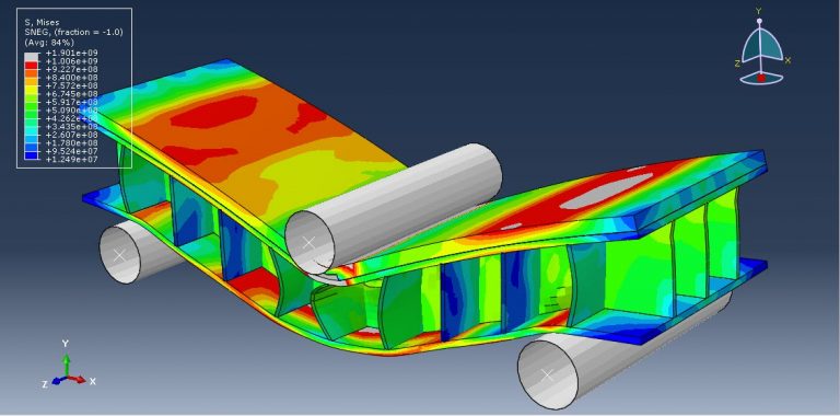
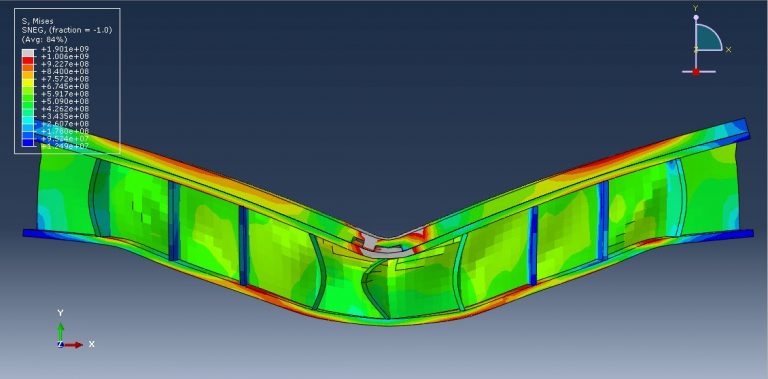
workshop 1: Composite three-point bending simulation (Ceramic-Steel-Aluminum)
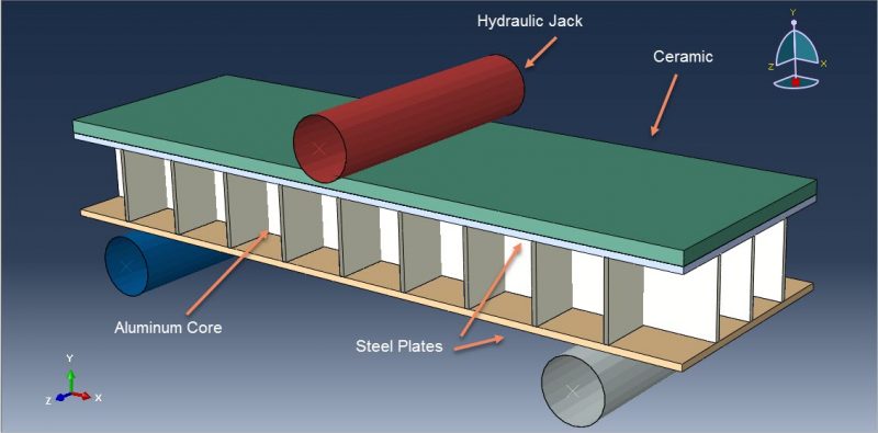
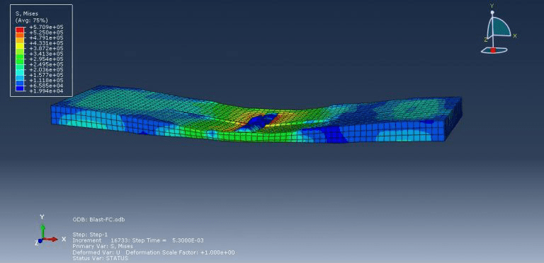
This lesson focuses on the numerical simulation of the three-point bending of a composite panel made of ceramic, steel, and aluminium in Abaqus. The plates are modelled as a solid three-dimensional part of steel and ceramic. A three-dimensional shell portion is modelled to represent the honeycomb-shaped aluminium core. The boundary zone and hydraulic jack are defined by three rigid bodies. Due to their lightweight nature, high stiffness, good damage tolerance, and capacity for absorbing energy, composite sandwich structures have been used in a variety of engineering applications.
Johnson-Cook plasticity and elasticity are used to model the behavior of steel. The Johnson-Cook plasticity model, a specific kind of Mises plasticity model with analytical forms of the hardening law and rate dependence, is suitable for the high-strain-rate deformation of various materials, including most metals. The Johnson-Holmquist damage model for ceramic material is assumed. The damage variable is assumed in this model to rise gradually with plastic deformation. The aluminium core material is modelled as an elastic-plastic material. This kind of analysis is suitable for the dynamic explicit step. Between the deformable part and general contact with friction acting as a contact property, the ideal core perfect contact is considered. In order to define interactions between rigid structures using ceramic and steel plates, the surface to surface contacts are used. The top rigid body is given displacement, while the two below rigid bodies are given fixed boundaries. To get good results, the mesh needs to be fine.
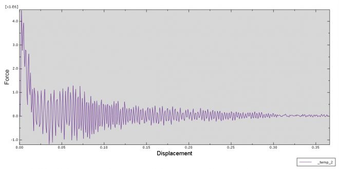
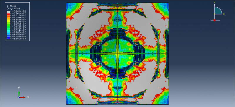
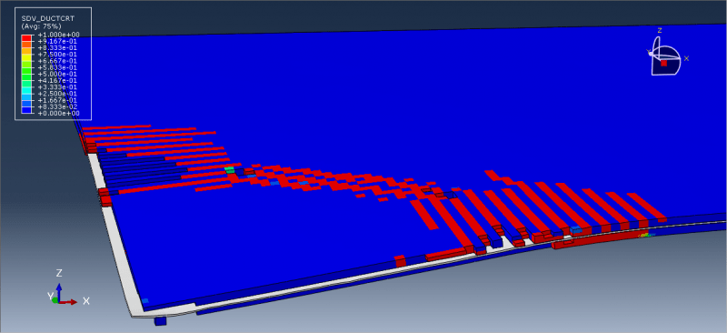
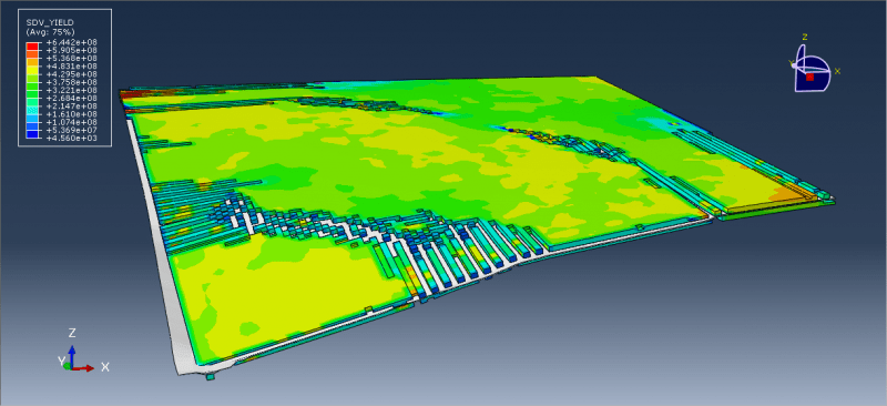
All simulation results, including ceramic plate failure and damage, aluminium core crushing, stress and strain, force-displacement diagrams, and more, are attainable.
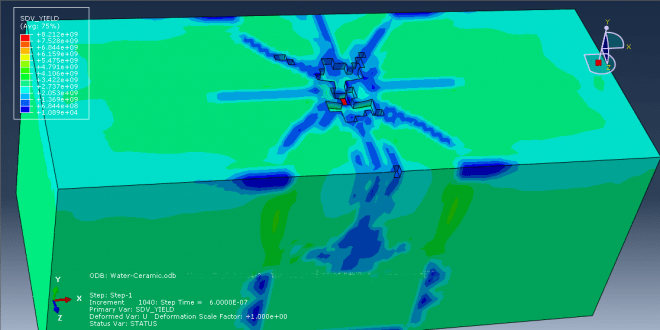
Workshop 2: Simulation of predicting the depth of penetration of alumina ceramics subjected to garnet impact
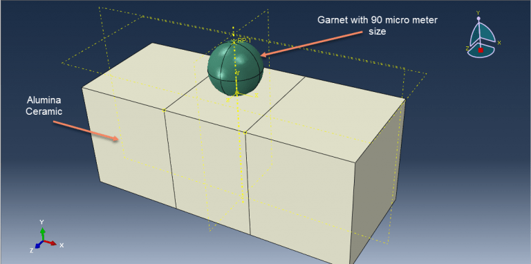
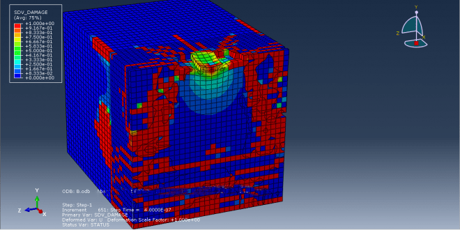
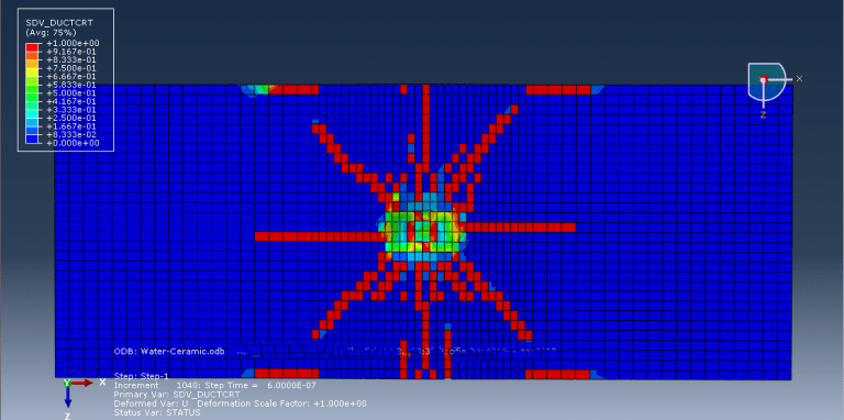
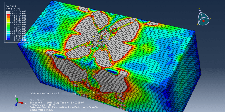
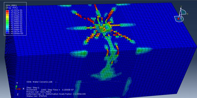
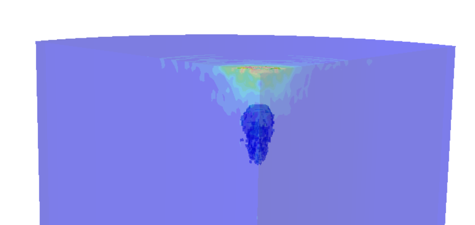
This tutorial has looked at a prediction model for the depth of penetration for alumina ceramics under garnet impact. The projectile and target were represented as three-dimensional parts. The JH-2 constitutive model was put up to explain how ceramic materials respond to high strain rates. A number of material constants are necessary for the JH-2 constitutive model to accurately predict the behavior of a specific ceramic material. The target measured 1000×400×400μm3. The following is the definition of the target’s boundary conditions: Nodes impacted by a particle on the target’s top face were released, but nodes impacted by particles on the target’s other five external faces remained fixed. In the vicinity of the impact on the target, a finer mesh was employed, while at a distance from the impact area, a relatively coarse mesh was used. In order to simulate the abrasive particle, rigid 3D solid (tetrahedral) elements were used.
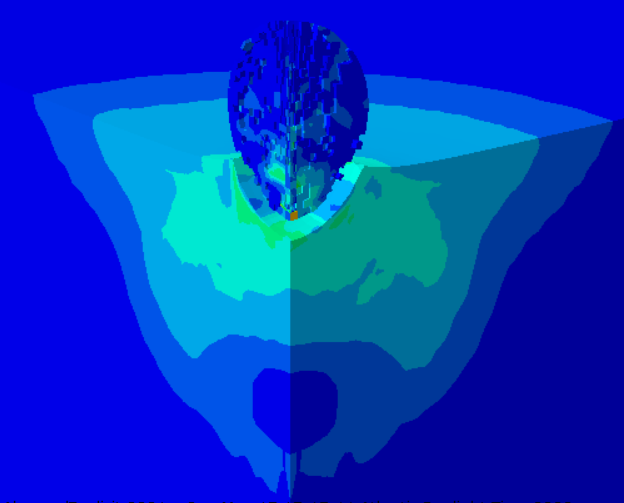
This kind of analysis is ideal for dynamic explicit method. The garnet’s initial speed is given as 700 meters per second. Garnet penetrated the target after the impact, and the damage variable is clear.
Workshop 3: Blast simulation and damage analysis of insulated concrete sandwich panel
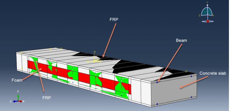
Sandwich panels made of insulated concrete have an interior layer of foam insulation between two outer concrete wythes. Because of their advantages of being lightweight and energy efficient, they are being used more and more. The two outer concrete wythes can be joined together using a variety of shear connectors. Fibre-Reinforced Polymer (FRP) shear connectors, which can remove thermal bridging and increase thermal performance, have been adopted more lately. Static and dynamic analyses are typically treated independently in Finite Element (FE) analytical methodologies. However, a nonlinear static analysis model would frequently diverge early based on a preliminary FE research due to the flexibility of the FRP shear connectors and the concrete cracking in insulated concrete sandwich panels.
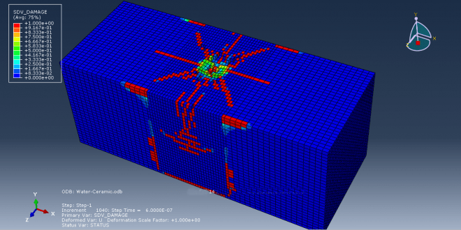
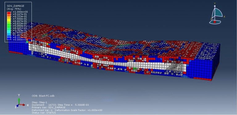
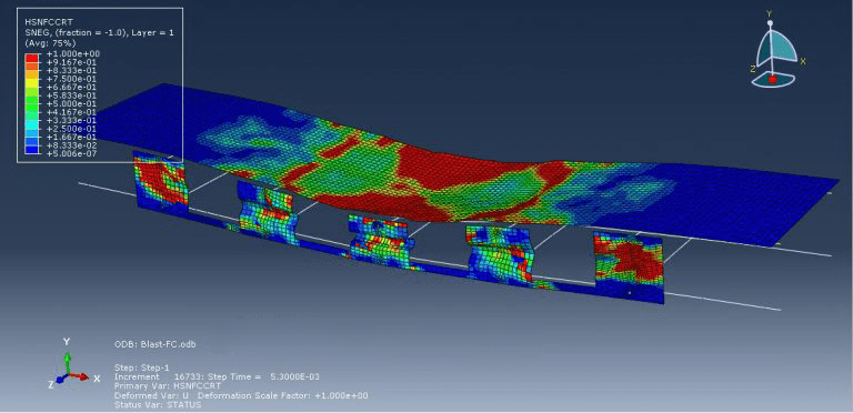
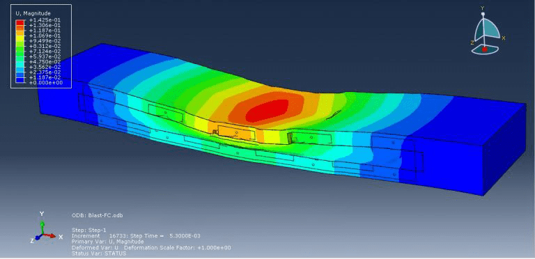
This simulation has looked at insulated concrete sandwich panel blast analysis and damage investigation. Beams are modelled as wire and composite as shell sections, while concrete and foam are represented as three-dimensional solid parts. The Johnson-Cook model for steel, Hashin’s damage criterion for composites, the crushable foam data for foam, and the Johnson-Holmquist damage model for concrete are all implied.
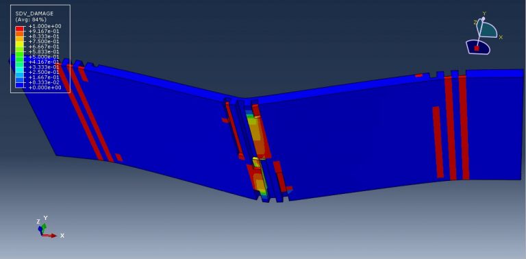
For this kind of study, the dynamic explicit and CONWEP air blast procedures are suitable. Because the beams are embedded in the concrete section, the interaction between concrete foam and concrete composites is regarded as perfect contact. A significant amount of damage was done to the concrete component during the simulation. Under the blast wave, the central portion of the concrete was destroyed, and the foam was entirely compacted. The composite damage criterion is also readily apparent.
workshop 4: Projectile impact simulation on cementitious material using SPH method
In this tutorial, projectile impact on cementitious material has been studied using finite element modelling of smooth particle hydrodynamics. A wide range of factors, including but not limited to the projectile and target geometry, impact velocity, projectile type, and projectile impact angle, all affect how well brittle cementitious armor panels perform under high-rate impact. The usage of HSC material as protective armor has been a popular choice for passive protection from weapon effects due to its comparably low cost, the convenience of rapid on-site fabrication, and high early strength. The protection of people in forward combat situations depends on an understanding of how such armor panels behave under high-rate ballistic impact. The cost of R&D efforts connected to novel materials and applications can be greatly reduced by accurately simulating the structural response of armor panels to such dynamic loads. The concrete panel and projectile are both modelled as three-dimensional solid parts.
Projectile behavior is modeled using the elastic properties of the steel material along with Johnson-Cook plasticity and damage criteria. The Abaqus concrete material model is divided into various models, such as CDP and brittle cracking. The Johnson-Holmquist damage model, which may be employed via the VUMAT subroutine or input file, has a greater performance when compared to the other material models. This kind of analysis is suitable for the dynamic explicit step. The contact property is employed as the friction coefficient in the general contact algorithm. The projectile’s initial velocity and the concrete panel’s fixed boundary condition are both utilized. For the concrete panel, the SPH formulation is utilized, and the mesh should be extremely small at the contact zone.
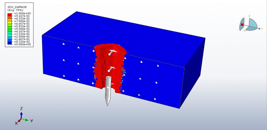
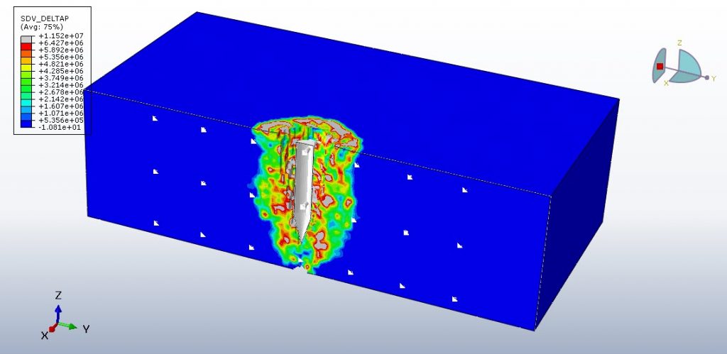
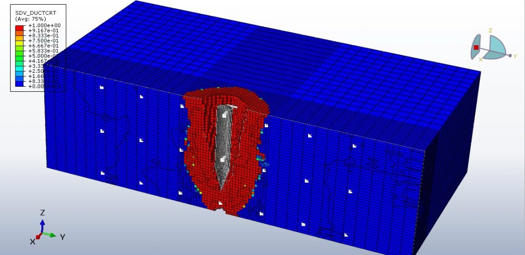
During the simulation, the missile penetrated the concrete, where it caused extensive damage. The availability of all outputs, including damage variables, stress, strain, and failure, is possible.
workshop 5: Simulation of high-velocity impact on the RC panel
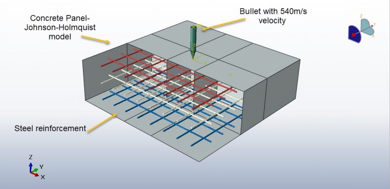
This tutorial looks into the High-velocity Bullet Impact on the RC Panel and Paper Validation. The paper is used to derive the dimensions. The concrete slab is depicted as a solid object with three dimensions. Three-dimensional wire pieces are used to represent the steel reinforcements. A discrete rigid body is used to represent the bullet.
Based on the information on the paper, the material is used. To take high-velocity impact damage into account, the concrete Johnson-Holmquist damage model that can be accessed through a VUMAT code or input file modification is chosen. Damage and JC hardening are taken into account when modeling steel reinforcement. It uses a dynamic explicit step with a step time of 0.001 seconds. It uses the general contact capability with erosion effect to take internal failure into account when generating input code. All sides of the panel are given the fixed boundary condition, and the bullet is given the initial velocity.
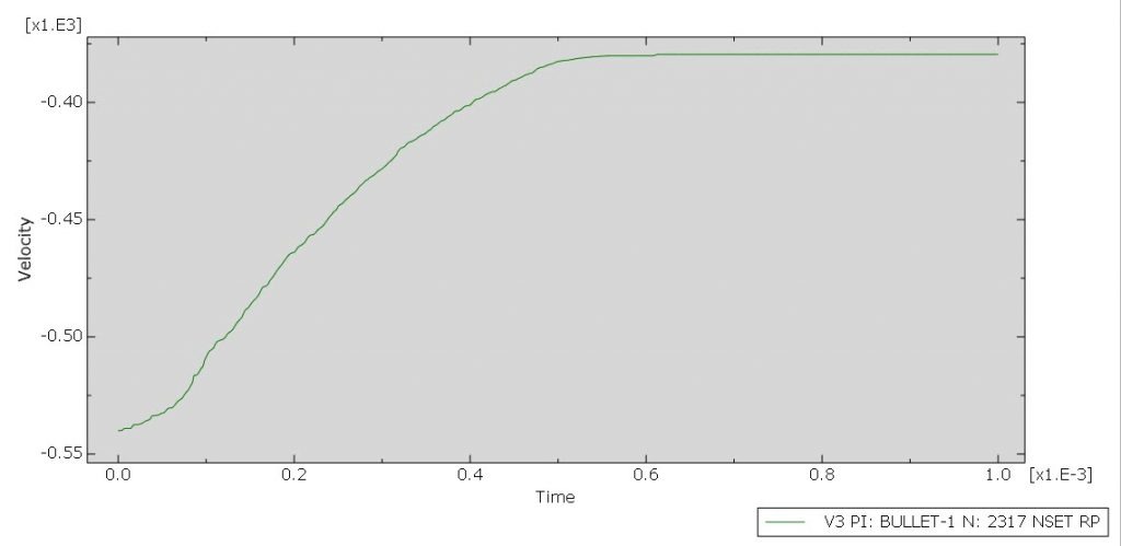
The simulation’s outcomes, including the bullet’s residual velocity, kinetic energy, deformation, and damage shape, match the results of the research. The residual velocity is the same for both the simulation and the paper.
All simulation results, including those for stress, strain, damage, etc., are available.
workshop 6: Air blast simulation on the RC beam reinforced with Banana-Epoxy lamina
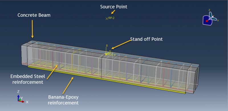
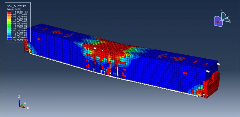
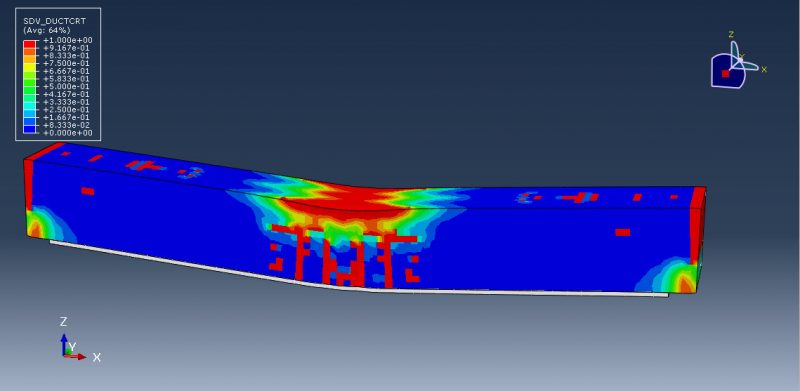
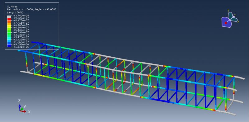
This tutorial examines the simulation air blast explosion over the banana-epoxy laminated RC beam reinforcement in Abaqus. The concrete beam is modeled as a solid part with three dimensions. The bar and strip are modeled as wire parts with three dimensions. The Banana-Epoxy component is modeled as an eight-layer, three-dimensional shell.
Abaqus includes a number of material models that are appropriate for this analysis to predict concrete behavior under severe compression loads, such as high velocity impact or blast explosion. Either a code or the capacity to read input files from a file can be used to create a new material model. The elasticity-engineering constant type is chosen to model Banana-Epoxy material. There are eight standard shell layers utilized, each with a different fiber orientation. The steel material with elastic-plastic behavior is chosen to represent bars and strips. This kind of analysis is suitable for the dynamic explicit step. In the concrete host, the steel reinforcements are regarded as an embedded region. It is expected that the contact between the banana-epoxy lamina and the concrete beam is perfect. The two ends of the beam are given the fixed boundary condition. For the results to be accurate, the mesh needs to be fine.
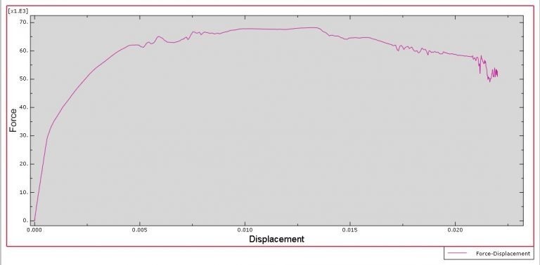
All of the findings from the simulation, including the force and displacement diagram, failure, damage variable, stress, and strain, are available.
Workshop 7: Damage analysis of the glass subjected to the air blast explosion
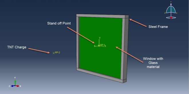
This course looks at damage analysis using finite element simulation of an air blast explosion over the glass. A three-dimensional portion is modelled for the glass and frame.
To simulate the behavior of steel frames, elastic-plastic material with Johnson-Cook damage criteria is employed. Abaqus has several models to represent glass materials, one of which is elastic and uses the shear modulus, Drucker-Prager plasticity, ductile damage criterion, and equation of state to get results for glass. Another method that can deliver exact results is the VUMAT subroutine or the embedded subroutine in the input file.
Perfect contact between the glass and frame and a dynamic explicit technique is used. To apply blast pressure to the glass surface, the CONWEP air blast technique is chosen. The frame has a fixed boundary condition given to it. It is necessary to utilize fine mesh for the glass since the mesh is essential to getting the right results.
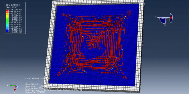
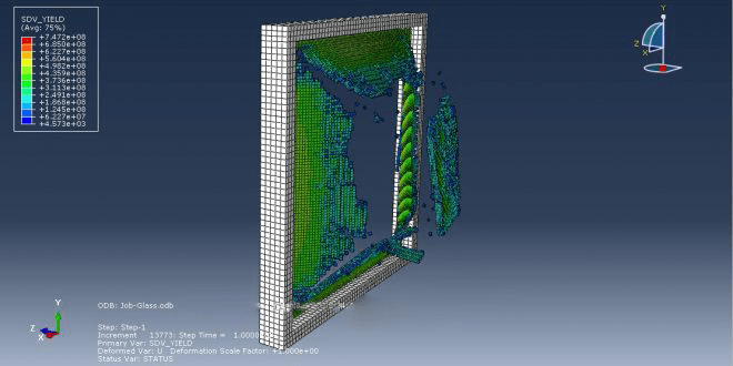
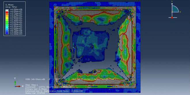
All outcomes, including the glass damage variable, stress, strain, pressure, and so forth, are possible after the simulation.
workshop 8: Air blast explosion simulation on the composite panel (glass + PVB)
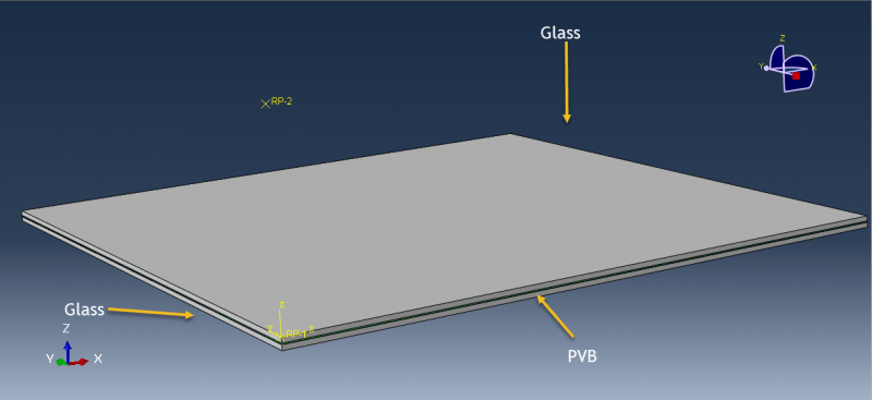
This tutorial looks at the Abaqus simulation of an air blast explosion over a composite panel made of glass and PVB. Air explosions produce distinctive pressure-time signatures that radiate outward. An injury-causing glass fragment is created when pressure waves impact with annealed glass. Laminated glass is used in blast loading threats to boost protection since the glass fragments stay attached to the interlayer, and the interlayer deforms to take the pressure loads. The two deformable and solid glass layers are employed. The PVB material is utilized as a solid part in between those glass layers.
The appropriate material model must be chosen in order to simulate glass behavior under intense loads like blasts or high-velocity impact. A few material models are provided by Abaqus and can be found in the input file, cae, and VUMAT subroutine. In this case, it is decided to define a new material model for the glass using input files. The elastic-plastic behavior is chosen to simulate PVB material. This kind of analysis is suitable for the dynamic explicit step. The mass scale method is considered to shorten both the simulation’s running duration and its stable time. Glass laminates and PVB are considered to have a perfect or ideal contact; however, surface-to-surface contact that is stiff can also be used. In order to apply blast load to the panel surface, the CONWEP air blast process is chosen. The model’s outside sides, and symmetry surfaces are given the fixed and symmetry boundary conditions. To get the right results, the mesh must be fine.
All simulation results, including stress, strain, damage, ductile damage, failure, and displacement, are provided after the simulation. The PVB portion has significantly deformed during the simulation, and the two glass layers have entirely failed.
workshop 9: Analysis of subsurface damage in glass subjected to ball impact
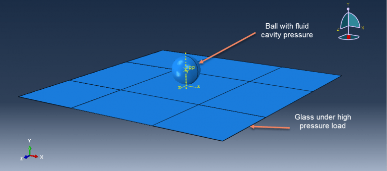
Analysis of the space debris and micrometeoroid impact flux via retrieved spacecraft surfaces requires knowledge of how brittle and ductile materials react to hyper-velocity impact. Solar panels and windows are examples of brittle material surfaces that are exposed in low earth orbit. Only a limited portion of the impactor parameters encountered in space may be accessed in lab research (velocity, diameter, density, shape, composition and impact angle). Glass is modeled as a solid part with a half-mm thickness, and the ball is modeled as a three-dimensional shell part in this simulation. Hyperelastic materials have been utilized to represent ball behavior, and a suitable material model should be employed to define glass behavior under high-pressure loads and high strain rates.
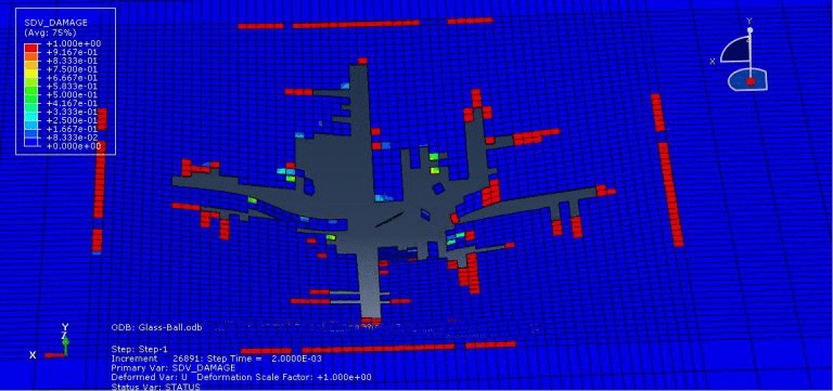
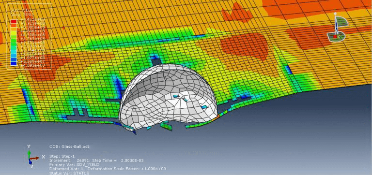
Since the impact phenomenon was originally a dynamic process, the step “dynamic explicit” is appropriate. The interaction is modeled as a surface-to-surface contact with friction behavior. The molar heat capacity and molecular weight of the gas inside the ball, along with the fluid cavity technique, have been employed in this tutorial to represent gas behavior. Smaller element sizes must be employed in the impact zone because glass requires a small mesh size to respond to impacts properly. The evident failure of the glass during impact caused a significant deflection of the ball.
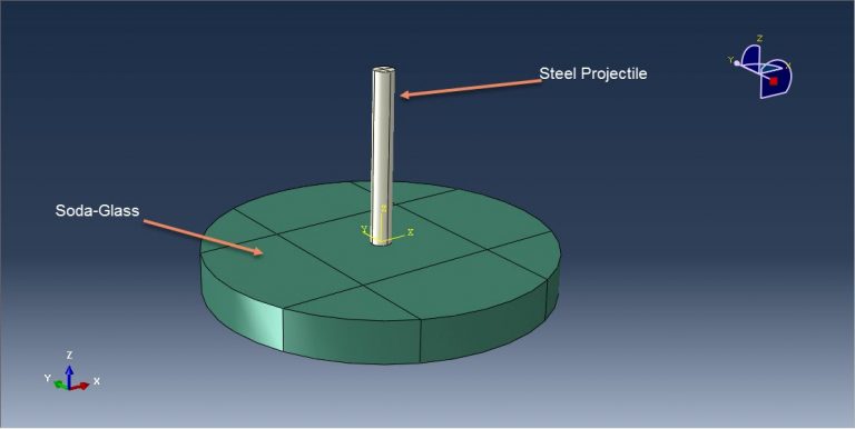
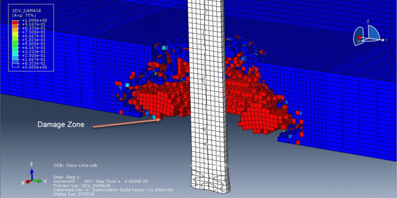
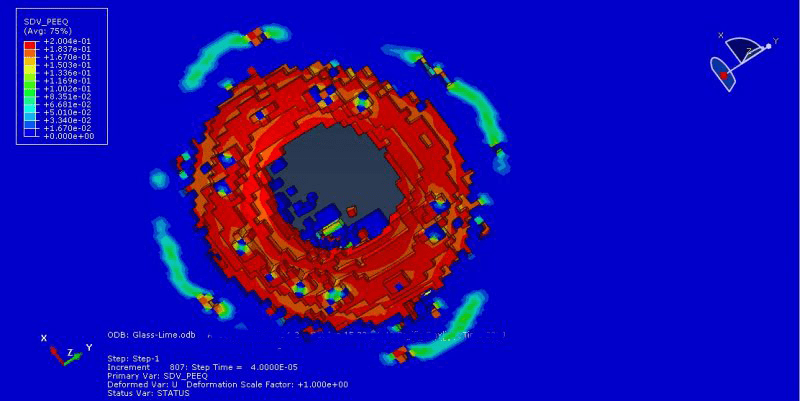
workshop 10: Damage analysis of steel projectile impact to the soda-lime glass
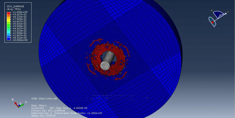
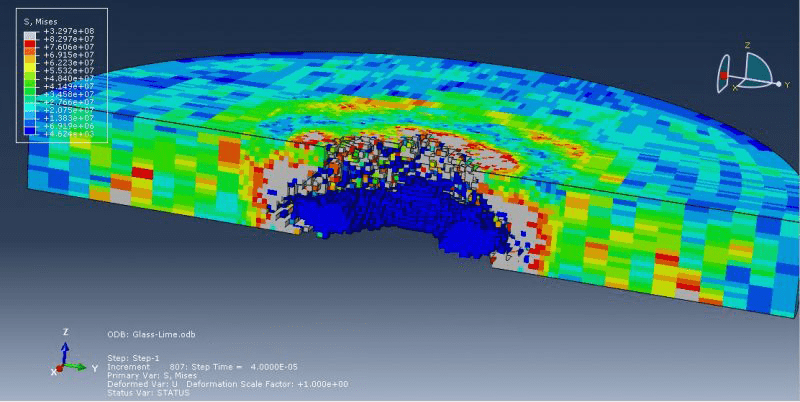
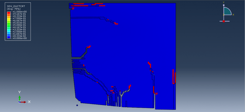
This tutorial examines the simulation of the ballistic impact of a steel bullet on the soda-lime glass during an Abaqus damage assessment. Glass is a very complicated substance, and modeling it is extremely difficult. Glass is highly dense and undergoes densification as shear, temperature, pressure, and time are applied. It has been proven that pressure has a major impact on a material’s strength, with higher pressures resulting in materials with greater strengths. Glass also seems to be strain-rate sensitive, and its loading rate causes an increase in its flexural strength. It has a high spall strength, and when subjected to shock loading, fracture starts at its elastic limit. Smaller samples of glass are stronger than bigger ones, as would be expected from a material that has brittle defects. During the plate impact experiment, it also experiences time-dependent inelastic deformation and strength loss. Glass and projectile are modeled as three-dimensional parts.
The projectile is made of steel, which has a rate-dependent elastic Johnson-Cook plasticity. Abaqus has various suitable material models that can be obtained via input files, CAE input files, or the VUMAT subroutine in order to model glass behavior under high-rate pressure loads. In this tutorial, a material model that takes into account every aspect of glass behavior is defined using input file capabilities.
Utilized are dynamic explicit steps with surface-to-surface contact. Assigned are the fixed boundary conditions for the area around the glass and the projectile’s beginning velocity. Mesh should be fine where it will influence because brittle failure requires small element sizes in order to anticipate with accuracy. All glass damage variables, stress, strain, and other results can be obtained after the simulation.
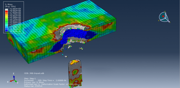
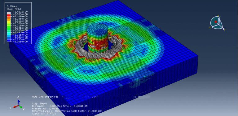
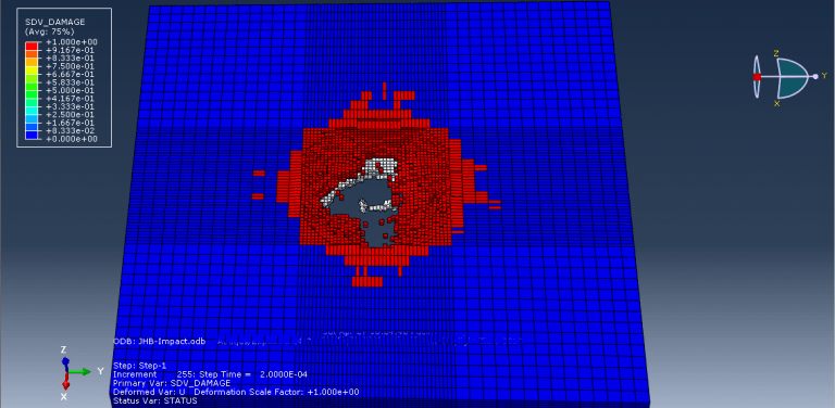
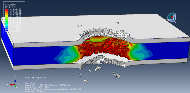
Workshop 11: Simulation of ballistic impact to the steel-silicon carbide-Steel trilayers
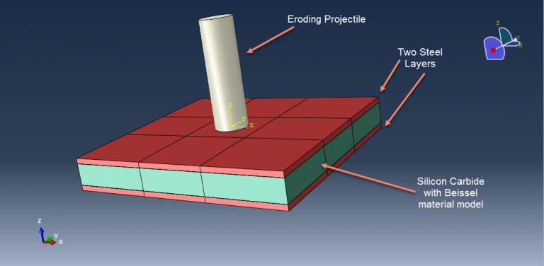
In this tutorial, Abaqus simulations of trilayers of steel, silicon carbide, and steel subjected to ballistic impact are examined. Ceramic-based armor systems can perform much better than monolithic metals with an equivalent areal density. Their performance is influenced by the relative proportions of ceramic and metal as well as how they are arranged spatially in addition to the intrinsic properties of the constituent materials. To retain vehicle mobility, load-carrying capability, and fuel efficiency in applications involving military ground vehicles, the armors must be made of lightweight materials and built to provide protection against a variety of projectile threats. In the current study, the effects of design on the ballistic performance of model composite armors made up of layers of ceramic and metal are investigated using numerical simulations using proven constitutive laws for the component materials. On the basis of equivalent areal density, comparisons are made.
Ceramic and two steel plates are modeled as three-dimensional parts. The projectile has a cylindrical part in the model.
To simulate the projectile elastic and plate properties of steel, data on plastic depending on the strain rate, the evolution of ductile damage, and shear damage are used. Johnson Holmquist Beissel has been used to model silicon carbide behavior under high strain rate deformation. The JHB model is made up of three main parts: an equation of state (EOS) for the pressure-density relation that can include dilation (or bulking) effects as well as a phase change, a damage model that transitions the material from an intact state to a fractured state, and a representation of the deviatoric strength of the intact and fractured material in the form of a pressure-dependent yield surface.
This kind of analysis is ideal for the dynamic explicit method. General contact has been defined as an input file by taking internal element erosion into consideration. The projectile’s initial velocity is set at 850 m/s. All damage variables are available after the simulation.
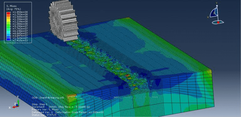
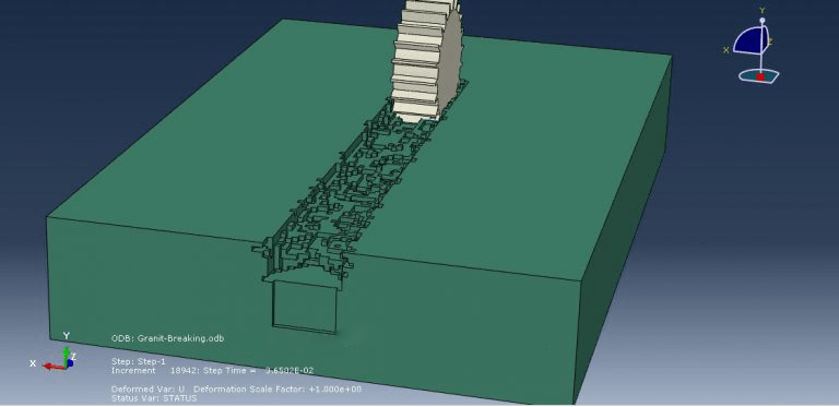
workshop 12: Rock breakage process by TBM rolling cutters simulation
Due to its quick rate of advancement, high efficiency, attractive tunnel creation, and minimal impact on the surrounding environment and security, the tunnel boring machine (TBM) has been widely used in tunnelling constructions. The modern era of tunnel boring machines was born in the early 1950s. Since Robbins (1987) provided a summary of tunnel-boring machine development used from the 1950s to the 1980s, numerous applications and models created for tunnel-boring machines have attracted much interest over the past 30 years. For example, using the shield method for urban tunnelling, the multi-micro shield tunnelling method for large rectangular cross-section tunnels, the compact shield tunnelling method for urban underground construction, a new model for predicting the performance of TBMs in hard rock under conditions of blocky rock, a new technique for predicting the performance of TBMs under mixed-face ground for project planning and optimization, analysis of TBM performance in highly jointed rock masses and fault zones, and so on.
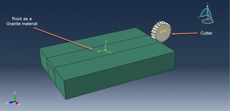
In this simulation, the rock is modeled as a deformable part, while the cutter is modeled as a three-dimensional rigid part. To get the right outcome from this simulation, using the correct material model is crucial.
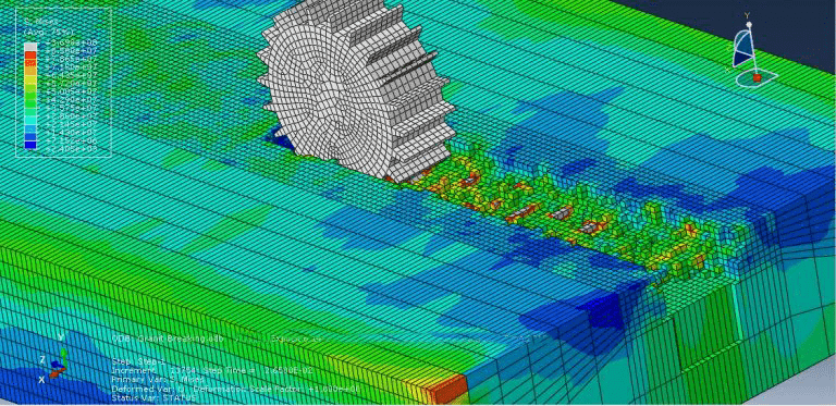
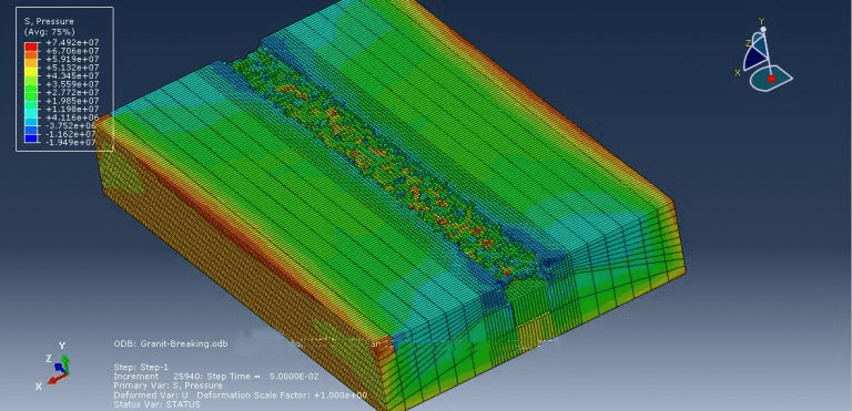
For this kind of study, the dynamic explicit step is appropriate, and the input file should examine general contact interaction with erosion. Following the simulation, it is clear that stones break.
It would be helpful to see Abaqus Documentation to understand how it would be hard to start an Abaqus simulation without any Abaqus tutorial. Moreover, if you need to get some info about the FEM, visit this article: “Introduction to Finite Element Method | Finite Element Analysis”. You don’t know which Abaqus software editions are suitable for you, Do not worry! This article would give you info about Abaqus editions: “How to download Abaqus? | Abaqus student & commercial edition” . One note, when you are simulating in Abaqus, be careful with the units of values you insert in Abaqus. Yes! Abaqus don’t have units but the values you enter must have consistent units. You can learn more about the system of units in Abaqus.







Kyle –
I have used this package to simulate the mechanical behavior of brittle materials at different strain rates, and I applied it to my material under gradual loading. The results were astonishing.
Experts Of CAE Assistant Group –
Thanks for your review