Hydroforming process simulation
Hydroforming process simulation is a powerful tool used to virtually replicate the entire hydroforming process before any physical materials are used. In simpler terms, it’s like running a dress rehearsal for your metal forming process on a computer.
Hydroforming itself is a metal forming technique where a tube is filled with a liquid and then pressurized. This pressure forces the tube to expand and conform to the shape of a surrounding die. While this process offers many advantages, it can also be complex and prone to trial and error.
That’s where hydroforming process simulation comes in. By creating a digital model of the entire process, engineers can analyze things like material flow, stress distribution, and potential for defects like thinning or cracks. This allows them to identify and address issues early on, saving time, money, and material waste.
Abaqus Hydroforming simulation
Within Abaqus hydroforming simulation, you can define the exact material properties of your tube, the geometry of the die, and the pressure profile of the fluid. This level of detail enables engineers to predict how the tube will behave under pressure, including factors like:
Wall thickness variations: Simulations can identify areas where the tube wall might become too thin or uneven during forming, allowing adjustments to the process before production begins.
Stress and strain localization: Predicting how stress and strain will be distributed throughout the tube helps ensure the final product meets strength and durability requirements.
Springback: The tendency of the metal to return slightly after forming can be anticipated and accounted for in the die design.
Introduction to Hydroforming | fluid pressure on sheet metal forming
Hydroforming stands out as a specialized metal forming technique designed to shape various metals such as steel, stainless steel, copper, aluminum, and brass. It uses fluid pressure on sheet metal forming. This process, serving as a cost-effective alternative to die molding, employs highly pressurized fluid to mold the metal, eliminating the need for traditional stamping and welding methods.
In contrast to older techniques that involve stamping two separate parts and welding them together, hydroforming proves more efficient in manufacturing. It enables the creation of intricate shapes and contours without the necessity for welding, leading to enhanced manufacturing efficiency. Hydroformed parts present a multitude of manufacturing benefits, including seamless bonding, heightened strength, and the ability to maintain superior surface quality for finishing touches.
Compared to conventional stamped and welded parts, hydroformed components offer advantages such as reduced weight, lower cost per unit, and an elevated stiffness-to-weight ratio. The process also allows for the streamlined production of components in a single stage, resulting in savings in labor, tools, and materials. In this tutorial, the emphasis is on exploring the intricacies of sheet hydroforming, showcasing its significant role in advancing modern manufacturing processes.
Types of Hydroforming
Hydroforming is a metal forming process that uses high-pressure fluid to deform a sheet or tube of metal into a desired shape. There are two main types of hydroforming:
- Sheet hydroforming:
In sheet hydroforming, a metal sheet is placed over a mold. A bladder, which is a flexible container filled with water or another fluid, is then placed over the sheet and sealed to the mold. The fluid pressure is then increased, forcing the sheet to conform to the shape of the mold. Sheet hydroforming can be used to create a wide variety of parts, including automotive body panels, aircraft skin, and industrial containers.
- Tube hydroforming:
In tube hydroforming, a metal tube is placed between two dies. The dies are then closed, and the tube is pressurized with water or another fluid. The pressure forces the tube to expand into the shape of the dies. Tube hydroforming is used to create a wide variety of parts, including automotive exhaust pipes, aircraft fuselage components, and industrial pressure vessels.
Applications of Hydroforming
These examples below illustrate the versatility and widespread adoption of hydroforming across various industries. The ability to create complex shapes from lightweight and strong materials makes hydroforming a valuable tool for manufacturing high-performance components that contribute to improved performance, efficiency, and safety in various applications.
Automotive Industry: Hydroforming is widely used to manufacture engine cradles, which are the structural support assemblies for engines in automobiles. These complex parts are formed from large steel tubes, creating a lightweight and strong structure that enhances vehicle stability and performance. Hydroforming is also employed to create lightweight and durable suspension components, such as control arms and shock absorber mounts. The precise control over material deformation allows for intricate geometries that optimize performance and enhance ride quality.
Aerospace Industry: Hydroforming is gaining traction in the aerospace industry for fabricating structural components of aircraft and spacecraft. The process is particularly suitable for creating lightweight, high-strength parts for fuselage sections, wing spars, and landing gear components. Hydroforming is also employed in the production of fuel tanks and pressure vessels for aerospace applications. The process ensures precise control over material thickness and wall curvature, enabling the creation of efficient and reliable containers for storing and pressurizing fluids.
Medical Industry: Hydroforming is finding applications in the manufacturing of orthopedic implants, such as hip and knee replacements. The process allows for the creation of custom-shaped implants that precisely match the anatomy of individual patients, improving comfort, stability, and long-term durability. Hydroforming is also being explored for the fabrication of other medical devices, such as stents, catheters, and surgical instruments. The precise control over material deformation enables the creation of complex geometries and intricate features that enhance device functionality and patient outcomes.
VDLOAD subroutine | Functional Fluid Pressure Loading
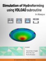
In the realm of simulation, precise load application is crucial. Enter the VDLOAD subroutine in Abaqus—an invaluable tool that goes beyond default options, allowing the definition of intricate and non-uniform loads. In this package, you will learn Functional Fluid pressure loading with the help of VDLOAD subroutine. (Hydroforming process simulation) Also, besides of Hydroforming, you will learn mastering VDLOAD, essential aspects like subroutine blocks, variable and parameter definitions, and the creation of loading formulations tailored to specific models. VDLOAD enables dynamic and spatially variable load definitions based on location, time, element number, or layer number, offering a versatile approach to load application. Elevate your simulation accuracy by delving into the capabilities of VDLOAD. For further details on VDLOAD and DLOAD subroutines, refer to this package: “Abaqus DLOAD Subroutine and VDLOAD Subroutine”.
Workshop: Advanced Hydroforming Simulation with Sophisticated Functional Fluid Pressure Loading
In Abaqus software’s Deep Drawing simulation, the VDLOAD subroutine becomes essential for specifying fluid pressure. The equation governing pressure definition relies on the instantaneous radius of the sheet. This workshop introduces you to the utilization of the Smooth Amplitude option, a method to define part displacement without introducing dynamic changes during problem-solving. The culmination involves a comparative analysis of simulation outcomes, considering both scenarios with and without fluid pressure, alongside a discussion on subroutine writing.
It would be helpful to see Abaqus Documentation to understand how it would be hard to start an Abaqus simulation without any Abaqus tutorial. Moreover, the general description of how to write a subroutine is available in the article titled “Start Writing a Subroutine in Abaqus: Basics and Recommendations “. If you even do not familiar with the FORTRAN, you can learn the basics via this article: “Abaqus Fortran “Must-Knows” for Writing Subroutines”.


Beatrice –
I recently came across the tutorial on hydroforming using the VDLOAD subroutine in Abaqus, and I was greatly impressed. The tutorial provides clear and comprehensive explanations of the fundamental principles of this method, and it has taught me precision and effectiveness in simulating hydroforming. I would like to express my gratitude to the CAE Assistant team for providing this valuable and comprehensive tutorial.
Experts Of CAE Assistant Group –
Thanks for your review. If you need more information about VDLOAD Subroutine, you can find it there.
https://caeassistant.com/product/vdload-dload-subroutine-abaqus-software/