1. Introduction to Woven Composites | Woven Fiber Composite
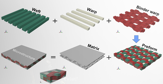
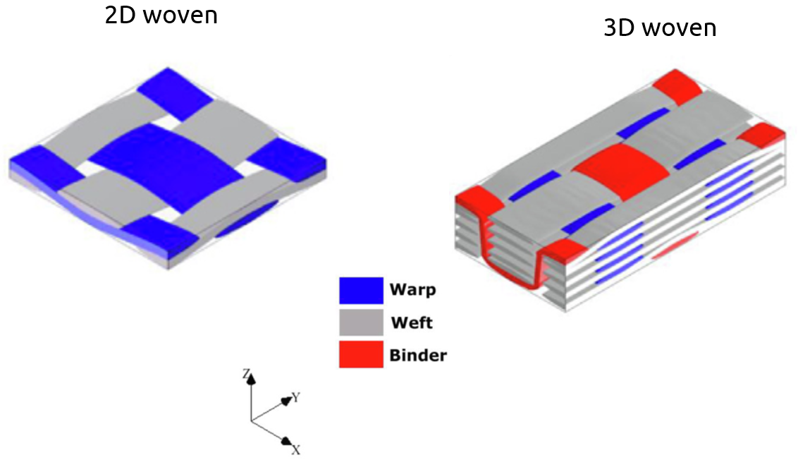
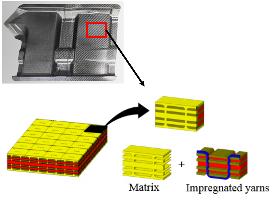
Woven composites are net-shaped composite structures where yarns are fully interconnected, much like a piece of fabric. These composites consist of yarns woven together in two directions, typically called the warp and the weft. In some cases, especially in 3D woven composites, a binder yarn connects these layers, offering enhanced strength in the thickness direction. This woven arrangement ensures that the composite behaves uniformly under stress, improving performance across multiple dimensions.
Woven composites can be categorized into 2D woven and 3D woven types. In 2D type, the structure consists of warp and weft yarns forming a sheet with limited thickness. These sheets can be stacked to create thicker structures. On the other hand, 3D type incorporate a binder, which adds strength in the thickness direction, making these composites more resistant to impacts and reducing the risk of delamination. This makes 3D woven composites significantly more durable than their 2D counterparts.
1.1. Advantages of woven composites over traditional composites
This type of composites offer several advantages over traditional laminated composites:
Elimination of Delamination: Unlike 2D laminated composites, which consist of separate layers bonded together, 3D woven composites are fully integrated. This eliminates the risk of delamination, a common issue in traditional composites.
Reduced Cracking: Traditional 2D laminated composites are prone to cracking, particularly in complex shapes like T-joints. In contrast, 3D woven composites maintain structural integrity even in complex geometries, reducing the risk of cracks.
Lower Production Times: The manufacturing process for 2D laminated composites involves stacking multiple layers, which is time-consuming. With woven composites, especially 3D woven structures, the production is faster and more cost-effective because the weaving process forms the composite in one step.
Cost-Effective: Woven composite materials can reduce overall costs, not only during manufacturing but also throughout their lifecycle. These materials are more durable, requiring less frequent replacements and repairs.
Higher Impact Resistance: The binder in 3D woven composites connects the layers in all three dimensions, which makes the material much stronger against impact forces.
1.2. Application of woven composites
Woven composites are used in a wide range of industries due to their superior properties. Applications include:
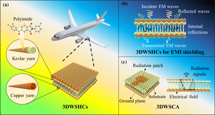
Aerospace Components: Woven composites are employed in thermal protection systems and high-strength aerospace parts, providing durability and resistance to harsh environments.
Figure 3: 3D Woven Spacer Hybrid Composite in airplane wing [Ref]
Medical Equipment: Their lightweight and durable nature make woven composites ideal for use in medical devices.
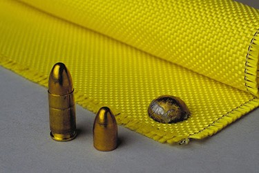
Military Equipment: Woven fiber composites are often used in bulletproof vests and other protective military gear due to their excellent impact resistance.
Figure 4: Woven composite in bulletproof vests
Acoustic Panels: Woven composites are also used in soundproofing applications.
An example of woven composite in action is the 3D woven spacer microstrip antenna, used in high-speed communication devices for aerospace applications.
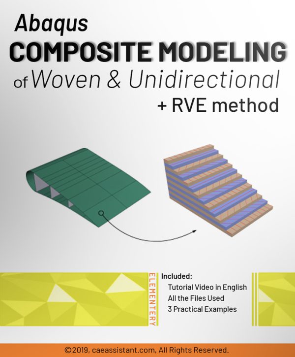
2. Woven composite modeling
Macro Modeling
In macro modeling, the composite material's properties are defined as a whole, without modeling its individual components. This method uses data from experimental tests to define the composite's properties in a software like Abaqus. The composite's layers are then modeled using the composite layup tool, making the process quicker and suitable for larger structures. For instance, to model a composite at the macro scale, you simply define the overall properties and the layer arrangement within the software, without simulating each fiber or yarn separately.
Micro Modeling
On the other hand, micro modeling involves modeling each component of the composite separately—warp, weft, binder, and matrix—before assembling them into a representative volume. This Representative Volume Element (RVE) represents a small section of the composite, allowing for a detailed simulation of its behavior. The RVE method ensures that the measurements and results from this small volume can be scaled to represent the whole composite. While micro modeling offers more detailed insights, it can be more complex.
Both modeling approaches have their advantages depending on the scale and detail required for analysis. In this tutorial, the focus will be on macro modeling using Abaqus.
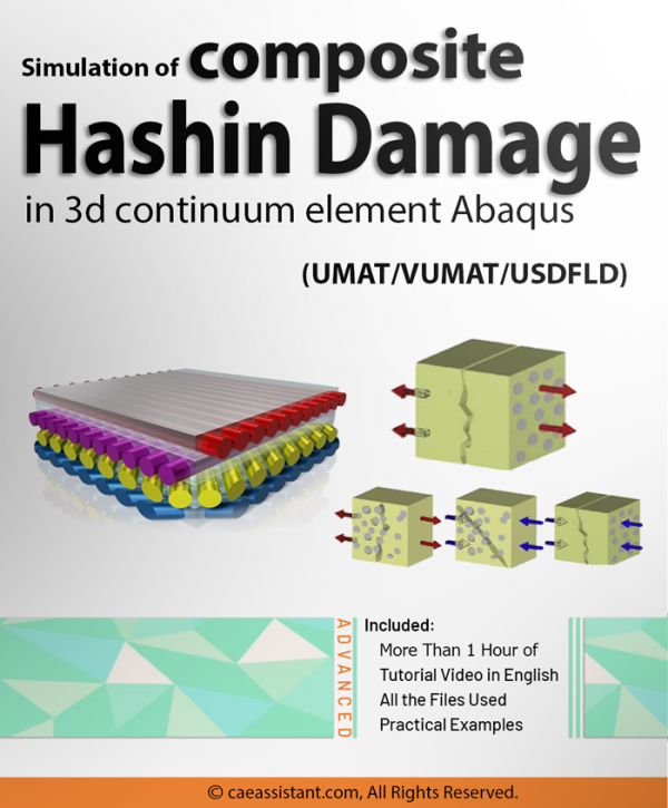
Woven composites are net-shaped composite structures that are fully interconnected by their yarns. Like a piece of cloth, the yarns are weaved together as warp and weft to create a composite structure. This package includes several components. First, it begins with an introduction to woven composites. Next, it provides a detailed explanation of macro modeling and offers guidance on how to perform it. The damage criteria employed in this package is a modified version of the Hashin criteria specifically designed for woven composites. Furthermore, the package demonstrates how to model damage using the USDFLD subroutine and Hashin relations. The subroutine is thoroughly explained, line by line, and a workshop is conducted to facilitate learning and practical application. Finally, the subroutine’s validity is confirmed through a verification process.
Woven composites are net-shaped composite structures that are fully interconnected by their yarns. Like a piece of cloth, the yarns are weaved together as warp and weft to create a composite structure.
Woven composites are advanced materials that offer a diverse range of capabilities, making them increasingly popular in various industries. These composites are formed by interlacing yarns or fibers at different angles, resulting in a layered structure that enhances their mechanical properties. One key advantage of woven composites is their exceptional strength-to-weight ratio, allowing for the creation of lightweight structures without compromising on durability. They exhibit excellent resistance to impact, fatigue, and corrosion, making them suitable for demanding applications in aerospace, automotive, marine, and sporting goods industries.
Moreover, woven composites possess inherent damage resistance due to their interlaced fiber architecture. The crisscrossing patterns of fibers distribute and absorb energy, minimizing the propagation of cracks and enhancing overall structural integrity. This property makes woven composites highly desirable for applications where damage tolerance is critical.
In this lesson, we will begin by introducing woven composites and highlighting their advantages over traditional composites. These advantages include the elimination of delamination, reduced risk of cracks, and enhanced impact resistance, among others.
Furthermore, we will explore various applications of woven composites in different industries. Some notable examples include their use in medical fabrics, engine rotors, aircraft frameworks, and military equipment. These applications showcase the versatility and effectiveness of woven composites in meeting the demanding requirements of these sectors.
By the end of this lesson, you will have gained a comprehensive understanding of the benefits offered by woven composites and their wide-ranging applications in diverse industries.
Lesson 2: Woven composite modeling
In lesson two, we will learn about woven composite modeling in different scales and determine on which scale we will simulate woven composites. We can model the composites in two scales: macro and micro scales.
In macro modeling, instead of modeling composite components separately, you can define composite material properties obtained from experimental tests in Abaqus with common Abaqus composite modeling methods.
In micro modeling, however, we need to model the components of the composite separately and then assemble them to create a small volume of it that represents the whole composite. Representative Volume Element (RVE) is a common method for micro modeling.
The first part of this lesson talks about types of damage (failure modes) in woven composite. Woven composites have three main failure or damage modes: fiber failure, delamination, and matrix failure. Note that you might see these failure modes with other names in some research articles.
We have fiber failure when fibers in warp or weft directions are damaged. The delamination occurs when there is damage between warp and weft fibers; usually, it happens when there is loading in the normal (thickness) direction. And we have matrix failure when the matrix cracks.
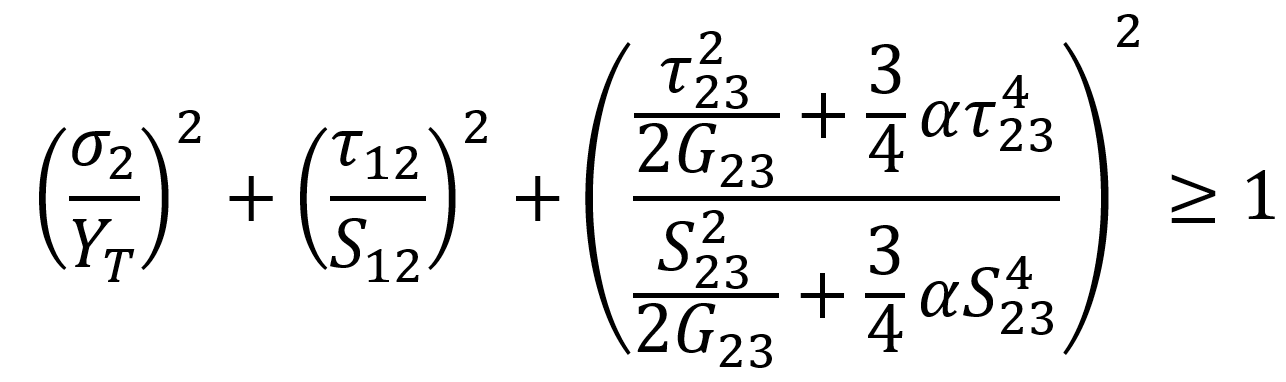
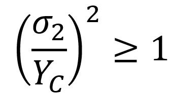
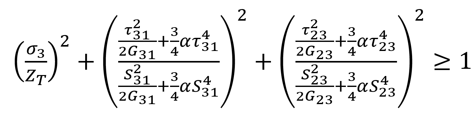
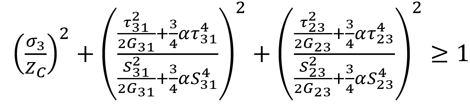
In the second part, the modified Hashin damage model for woven composites is presented. This model determines damage directions (warp, weft, and normal directions), and failure modes in both tensile and compressive loadings.
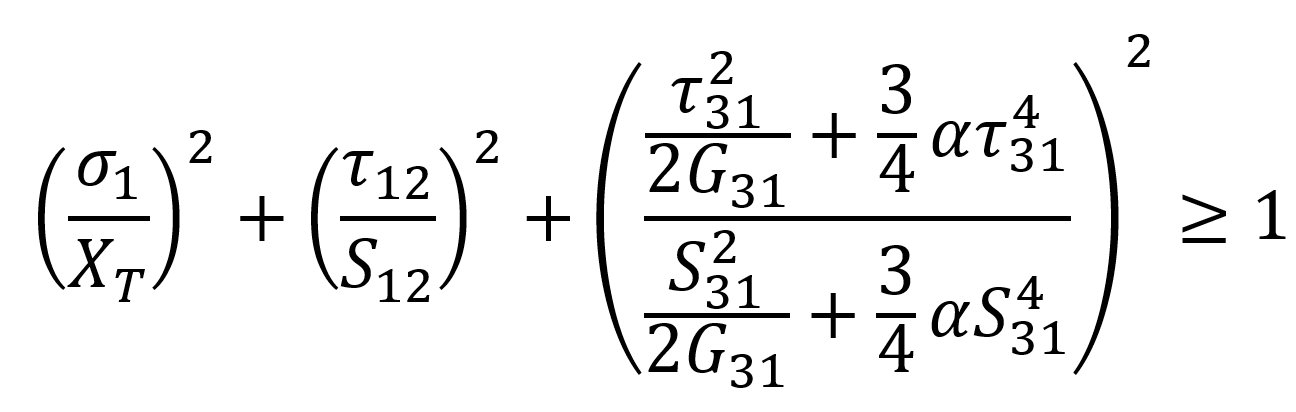
Fiber failure in tensile, direction 1 (warp direction), :
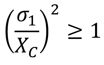
Fiber failure in compression, :
Fiber failure in tensile, direction 2 (weft direction), :
Fiber failure in compression, direction 2 (weft direction), :
Delamination in tensile, direction 3 (normal direction), :
Delamination in compression, direction 3 (normal direction), :
Each of the above equations is explained completely along with their variables. Also, the differences between the conventional Hashin damage criteria used for traditional composites are explained.
Lesson 4: How to apply the damage criterion in Abaqus
In this concluding lesson, we will delve into the application of the modified Hashin criteria using the USDFLD subroutine to our model. To begin, we will provide a comprehensive explanation of the code’s flowchart, enabling a clear understanding of how the subroutine operates. Next, we will meticulously describe the code line by line, providing you with the necessary knowledge to write similar subroutines. This detailed breakdown will ensure a thorough comprehension of the process involved in implementing subroutines like the one at hand.
Finally, we will validate the subroutine’s functionality by comparing its results with experimental data. This crucial step will confirm the accuracy and reliability of the subroutine, ensuring that it aligns with real-world observations.
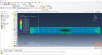
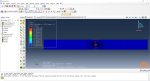
Workshop: Damage simulation of a woven composite plate
The initial focus of this discussion is to describe the problem at hand, which entails modeling a plate featuring a circular hole at its center. We will provide details regarding the material properties employed in the model, as well as the boundary conditions applied to ensure a comprehensive understanding. Subsequently, we will guide you through the modeling process in Abaqus, providing a step-by-step explanation to ensure clarity. This comprehensive walkthrough will enable you to grasp the intricacies of the modeling procedure and successfully implement it. Moving forward, we will thoroughly delve into the results obtained from the model. A comprehensive discussion will be conducted, encompassing various aspects such as failure modes, damage initiation, and progressive damage.
If you are working on Abaqus composite damage and need some resources about composite FEM simulation, click on the Abaqus composite analysispage to get more than 20 hours of video training packages on composite materials simulation. I hope you have got enough information about the woven composite damagesimulation; if you need more information about this package, please get in touch with us via online chat on the left side of this page. It would be helpful to see Abaqus Documentation to understand how it would be hard to start an Abaqus simulation without any Abaqus tutorial.
After purchase, you can access the subroutine immediately.
The video files and workshops will be available 2 months later after purchase.
How to make settings for written subroutine in the software for composite material damage and assign subroutine to the model?
How to view the results of this modeling for the outputs defined in the subroutine?
Shipping and Delivery
All the package includes Quality assurance of training packages. According to this guarantee, you will be given another package if you are not satisfied with the training, or your money is returned. Get more information in terms and conditions of the CAE Assistant.
All packages include lifelong support, 24/7 support, and updates will always be sent to you when the package is updated with a one-time purchase. Get more information in terms and conditions of the CAE Assistant.
Notice: If you have any question or problem you can contact us. Ways to contact us: WhatsApp/Online Support/Support@CAEassistant.com/ contact form. Projects: Need help with your project? You can get free consultation from us here.
To access tutorial video run the .exe file on your personal pc and send the generated code to shop@caeassistat.com and wait for your personal code, which is usable only for that pc, up to 24 hours from CAE Assistant support.
Here you can see the purchase process of packages: Track Order
Features
1 review for Simulation of woven composites damage in Abaqus
luka –
Rated 5 out of 5
While the workshops focus on developing a subroutine for modeling damage in woven composites, it may be useful to provide more information on other methods for simulating composite damage, such as cohesive zone modeling or continuum damage mechanics. This would give users a more comprehensive understanding of the different approaches available for modeling composite damage.
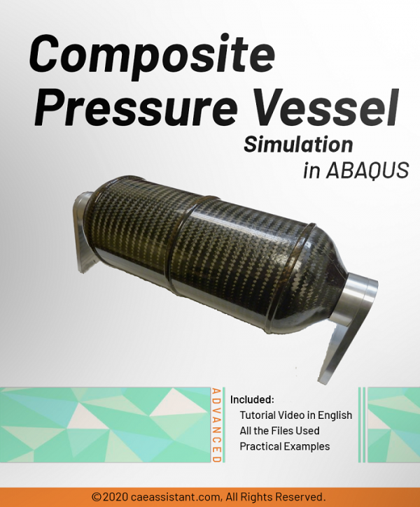
Pressure vessels are made using different methods today, and one of them is filament winding. This package shows the simulation of composite pressure vessels made using the filament winding method.
In this training package, three winding methods, planar, geodesic, and isotensoid, have been taught for filament winding pressure vessels. In this tutorial, two general methods also have been presented for simulating filament wound pressure vessels. One uses the Abaqus graphical user interface(GUI), and the other uses the Python script. On the other hand, two criteria, Tsai-Hill and Puck, have been used to model damage in the composite. A UMAT subroutine has been used to use the Puck criterion.
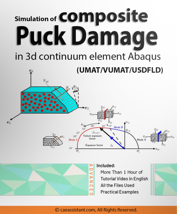
The Puck criterion is an essential damage model for composite materials, considering both fiber and matrix failures simultaneously. It provides a practical way to predict the onset of damage in composites under various loading conditions. This training package is focused on simulating composite PUCK damage in 3D continuum elements using UMAT, VUMAT, and USDFLD subroutines in Abaqus. It covers different types of failure in composites, including fiber failure, matrix cracking, delamination, and interfacial failure, as well as criteria for predicting failure modes in composites that are dependent or not dependent on each other, such as the Tsai-Wu and Tsai-Hill criterion, respectively. Additionally, the package covers composites' most commonly used damage criteria, including the Puck criterion. The package provides step-by-step guidance on simulating composite Puck damage using each of the subroutines mentioned above in Abaqus.
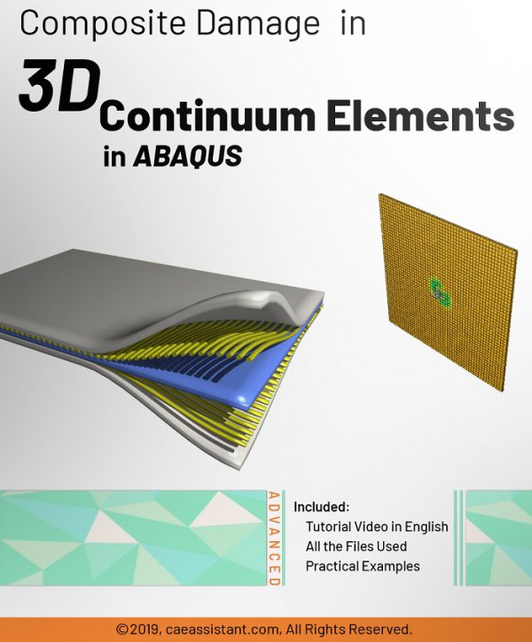
In this training package, the 3D continuum HASHIN damage initiation model is prepared via three subroutines (USDFLD, UMAT and VUMAT).This training package teach you subroutines line-by-line. It should be noted that after damage initiation, failure occurs suddenly and in the form of a reduction in properties in the model. The HASHIN theory for this package is based on Kermanidis article titled” FINITE ELEMENT MODELING OF DAMAGE ACCUMULATION IN BOLTED COMPOSITE JOINTS UNDER INCREMENTAL TENSILE LOADING “.
If you are a graduate or Ph.D. student, if you are a university professor or an expert engineer in the industry who deals with simulation software, you are definitely familiar with the limitations of this software in defining the material properties, loading or meshing, interaction properties, and etc. You have certainly tried to define the properties of materials based on advanced fracture theories in finite element software and are familiar with their limitations and problems.
Now, here is your solution. Start writing subroutines in finite element software and overcome the limitations. With the tutorials in the Golden Package, you will learn how to write 8 subroutines in Abaqus software professionally.
The Hashin failure criteria is a set of failure criteria developed specifically for composite materials. It predicts different failure modes in composites based on the stresses experienced by their constituents (fiber and matrix). The criteria are widely used in engineering and computational models to assess composite material performance under mechanical loading. The criteria, while highly efficient and widely used, pose challenges when implemented in numerical simulations. Abaqus has emerged as a powerful tool to address these challenges, enabling the prediction of damage initiation and its progression (via stiffness reduction) based on the Hashin criteria. However, a key limitation of Abaqus is its applicability being restricted to 2D plane stress elements. To overcome this limitation, we developed a VUMAT subroutine in this project. This custom subroutine extends the capabilities of Abaqus, allowing for the simulation of damage initiation and propagation in 3D problems in accordance with the Hashin criteria. It should be mentioned that this subroutine includes gradual progressive damage based on the energy method. This complex subroutine could be used for static and dynamic problems.
A notable point is that in one of our other packages, we also provide training on using Abaqus subroutines to analyze the Hashin criterion. However, in that package, damage occurs instantaneously. In the current package, we have modeled the progressive Damage, which is more complex but could be more beneficial for solving your specific problems.
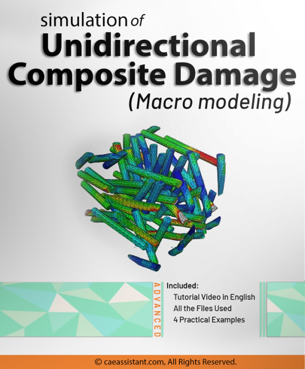
This package is about Unidirectional Composite Damage tutorial and applies various theories to initiate and progress damage in composite materials based on ABAQUS capabilities for different elements. As you know, according to the modeling done by the micro or macro method, the way of defining the Abaqus composite damage completely follows the separate method in ABAQUS. This training package is customized for Abaqus composite macro modeling. There are 5 different unidirectional composite examples to help you master unidirectional composite simulations and Abaqus composite laminate damage modeling. You can see the examples in the syllabus below.
This training package provides comprehensive basic information and examples on for composite modeling in ABAQUS FEM software in accordance with subsequent packages. The methods of modeling these materials are in two ways: micro and macro, which vary according to the type of material selected and how they are used. Next packages focus on two modeling types professionally.


luka –
While the workshops focus on developing a subroutine for modeling damage in woven composites, it may be useful to provide more information on other methods for simulating composite damage, such as cohesive zone modeling or continuum damage mechanics. This would give users a more comprehensive understanding of the different approaches available for modeling composite damage.