The laser forming process is performed by applying thermal stresses to the workpiece surface by heating the surface with a laser beam. These internal stresses induce plastic strains in the part resulting in local elastic-plastic deformation (Laser-induced plastic deformation). In this laser forming simulation tutorial the DFLUX subroutine is used to apply heat flux (Gaussian heat distribution) dependent on location and time in finite element simulation. For example, the linear heating processes of laser forming and welding (with a slight simplification) can be simulated by this subroutine. In the linear heating process, by applying heat flux to the surface of a sheet, a thermal gradient is created in its thickness. This thermal gradient causes permanent deformation of the sheet. To simulate the laser forming process, it is necessary to apply a time and location-dependent heat flux to the sheet. In this type of loading, a heat flux is applied on the plate, which is defined using the DFLUX subroutine, including the laser power, movement speed, beam diameter, absorption coefficient, and laser movement path according to the designed experiments (Laser forming process parameters). To verify this Abaqus laser forming simulation, the simulation results and experimental results of sheet deformation (U) are compared. The displacement of the sheet in the simulation is in good agreement with the experimental results.
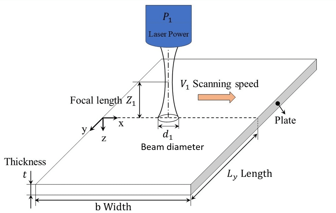
The laser forming process is performed by applying thermal stresses to the workpiece surface by heating the surface with a laser beam. These internal stresses induce plastic strains in the part resulting in local elastic-plastic deformation. The practical application and variables of the laser forming process are shown in figure 1. In general, the variables of the laser forming process are the laser power, feeding speed, beam diameter, absorption coefficient, laser movement path, etc. In this Laser forming simulation tutorial you will learn how to do a solid simulation in this subject.
Figure 1: Variables of the laser forming process
2. Abaqus laser forming simulation (PDF File)
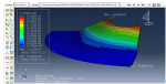
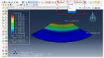
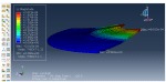
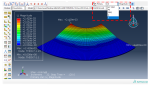
In this example, while familiarizing with the DFLUX subroutine, it is taught how to simulate the laser forming process using this subroutine. The heat flux per unit area (HFL), nodal temperature distribution, stress distribution field, displacement distribution field, general form of sheet deformation, etc., are the output results of this analysis. To verify this Abaqus laser forming simulation, the simulation results and experimental results of sheet deformation (U) are compared. The displacement of the sheet in the simulation is in good agreement with the experimental results. This project is designed to enhance participants’ understanding of the DFLUX subroutine in simulating processes such as laser forming.
2.1. PROBLEM DESCRIPTION
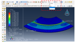
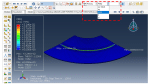
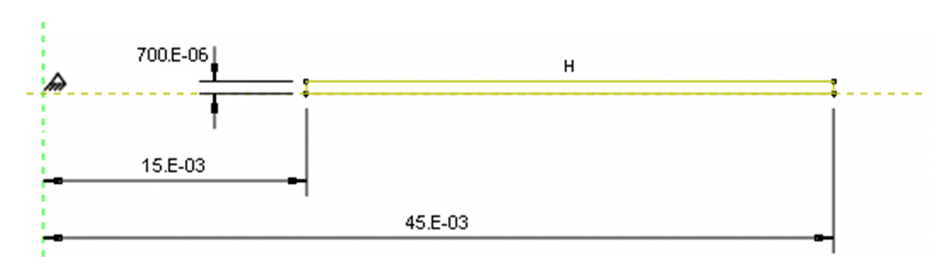
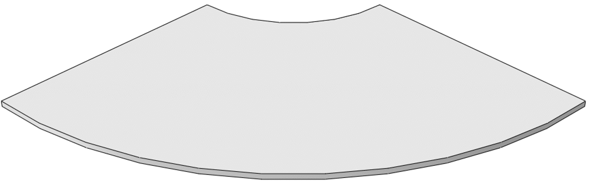
In this example, the used sheet material is AISI 1010 with a density of 7800 Kg/m3 , which is used in drawing and forming processes. The sheet is considered a quarter of a ring with an outer radius of 45 mm and an inner radius of 15 mm and a thickness of 0.7 mm. Laser power 80 W, feed speed 25 mm/s, beam diameter 1.5 mm, and the radius of the movement path 30 mm from the center of the circle are considered.
The DFLUX subroutine is used to apply heat flux dependent on location and time in finite element simulation. For example, the linear heating processes of laser forming and welding (with a slight simplification) can be simulated by this subroutine. In the linear heating process, by applying heat flux to the surface of a sheet, a thermal gradient is created in its thickness. This thermal gradient causes permanent deformation of the sheet. To simulate this process, it is necessary to apply a time and location-dependent heat flux to the sheet. In this type of loading, a heat flux is applied on the plate, which is defined using the DFLUX subroutine, including the laser power, movement speed, beam diameter, absorption coefficient, and laser movement path according to the designed experiments.
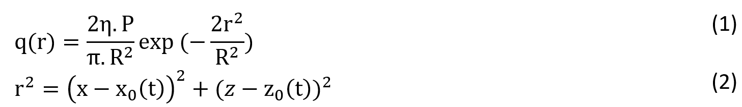
The heat intensity of the laser beam on the sheet surface is modeled using an ideal Gaussian distribution, where the heat flux is described as follows:
Where q(r), is the required heat flux intensity on the surface of the material, η is the heat transfer efficiency, P is the power of the laser beam, R is the radius of the laser beam, r is the distance from the center of the laser beam, and (x0, z0) is the location of the beam.
If the laser head moves with speed V on the z-axis, we will have:
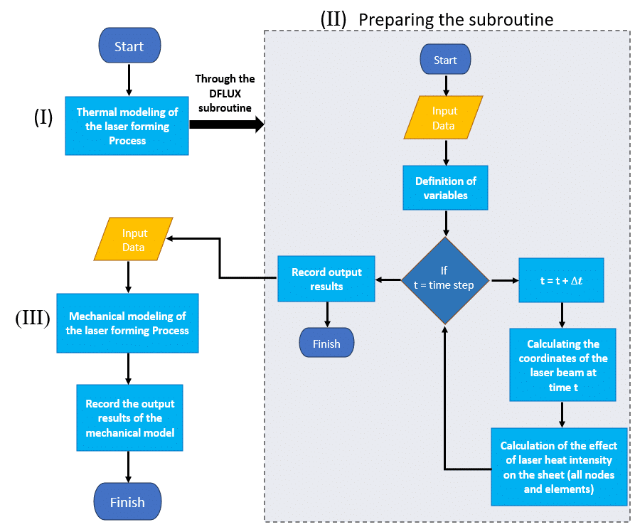
Figure 4: Flowchart of the modeling process of laser forming
In summary, the laser forming simulation procedure is as follows:
Thermal modeling of the laser forming Process
Setting up the software environment and choosing Abaqus units
Creating the part and partitioning it properly
Defining the thermal properties of AISI 1010 and creating the relevant section
Making an instance of the model in the Assembly module
Creating two “Heat transfer” steps (laser movement and cooling steps), choosing the outputs
Defining the interactions
Applying the boundary conditions and load for the thermal section of the modeling
Generating elements and assigning element types
Calling the subroutine
Submitting the job
Viewing the results of the thermal modeling section
Preparing the subroutine
Mechanical modeling of the laser forming Process
Defining the mechanical properties of AISI 1010 and creating the relevant section
Creating two “Static, General” steps (laser movement and cooling steps), choosing the outputs
Applying the boundary and initial conditions for the mechanical section of modeling (using the calling of output results of thermal modeling)
Changing the type of elements (the type of elements should be adjusted according to the mechanical analysis.
Submitting the new job
Viewing the results of the mechanical modeling section
3. Workshop (Video file): A step-by-step guide on the laser forming simulation
In the workshop, we selected an AISI 1010 sheet under the heat flux caused by a laser beam. The workshop provides a full step-by-step guide through a video to simplify the simulation of the laser forming process.
In the video, we used two “Heat transfer” steps for thermal modeling and two “Static, General” steps for mechanical modeling and defined all the necessary outputs for the laser forming process. Then, the non-uniform mesh pattern will be used in such a way that very fine meshes will be employed near the scan path (due to the presence of high heat flux in this area) and coarser meshes will be employed in the regions far from the scan path. With this meshing pattern, we will achieve both demands of accurate results for simulation and reduction of computing time. Following this, we defined the thermal interactions between the sheet and the environment. Then we applied the boundary conditions and load, such as heat flux, initial temperature of the sheet, etc. Finally, we show how to call the subroutine, submit the job, and extract the results in full detail (for both thermal and mechanical modeling parts of the laser forming process).
To verify this model, the simulation results and experimental results of sheet deformation (U) are compared. The displacement of the sheet in the simulation is in good agreement with the experimental results.
It would be helpful to see Abaqus Documentation to understand how it would be hard to start an Abaqus simulation without any Abaqus tutorial.
One note, when you are simulating in Abaqus, be careful with the units of values you insert in Abaqus. Yes! Abaqus don’t have units but the values you enter must have consistent units. You can learn more about the system of units in Abaqus.
Shipping and Delivery
All the package includes Quality assurance of training packages. According to this guarantee, you will be given another package if you are not satisfied with the training, or your money is returned. Get more information in terms and conditions of the CAE Assistant.
All packages include lifelong support, 24/7 support, and updates will always be sent to you when the package is updated with a one-time purchase. Get more information in terms and conditions of the CAE Assistant.
Notice: If you have any question or problem you can contact us. Ways to contact us: WhatsApp/Online Support/[email protected]/ contact form. Projects: Need help with your project? You can get free consultation from us here.
To access tutorial video run the .exe file on your personal pc and send the generated code to [email protected] and wait for your personal code, which is usable only for that pc, up to 24 hours from CAE Assistant support.
Here you can see the purchase process of packages: Track Order
Features
5
Rated 5 out of 5
1 review
Rated 5 out of 5
1
Rated 4 out of 5
0
Rated 3 out of 5
0
Rated 2 out of 5
0
Rated 1 out of 5
0
1 review for Laser Forming Process Tutorial in Abaqus
This educational package really helped me understand and implement the laser forming simulation process in Abaqus very well. The step-by-step video guide along with the input and output files was very useful, and I was able to quickly build the model and compare the results with experimental data.
The key things I learned in this educational package include:
Using the DFLUX subroutine to apply time and spatially dependent heat flux
Simulating the effects of temperature gradients through the sheet thickness and the resulting permanent deformation
Comparing the simulation results with experimental data and observing good agreement
Additionally, I would like to work with the DFLUX subroutine in a more specialized manner. Do you have any specific packages related to this? I would appreciate if you could recommend any.
Friction stir welding (FSW) involves complex material flow and plastic deformation. Welding parameters, tool geometry, etc., have important effects on the material flow pattern, heat distribution, and eventually on the structural evolution of the material. In an Abaqus friction stir welding example, the rotational movement of the tool and its friction in contact with the workpiece causes heat generation, loss of strength, and an increase in material ductility around the tool. The feeding movement of the tool causes the material to transfer from the front of the tool to the back of it, and eventually leads to a join. Therefore, heat plays an important role in this process, and parameters such as rotational speed, tool feeding speed, tool geometry, and others, all somehow have a significant impact on controlling the amount of incoming heat, the disturbance and flow pattern of the material, the evolution of the microstructure, and the quality of the resulted weld. This friction stir welding example simulation tutorial shows you how to simulate the Abaqus FSW simulation process in such a way that you can accurately predict the effect of all relevant parameters on the process. In most of the implemented projects, welding mud, and welding defects (welding overfills and overlaps, weld gaps) are not visible and predictable; however, in this simulation, these cases are visible. This project is designed to enhance participants' understanding of how to accurately simulate the FSW process to see the weld's general appearance.
This package is related to Thermal Analysis in Abaqus. This package helps Abaqus users to simulate professionally.
In general, Abaqus can solve the following types of heat transfer problems (For thermal and thermo-mechanical problems):
This training package fully covers the various possible methods for welding simulation. First, an introduction to welding and two basic categories of welding, fusion and non-fusion welding. Next, the theories and the elements used to simulate the welding will be explained. These theories are Lagrangian, Eulerian, ALE, and SPH. After that, you will learn how to apply these theories with different methods, such as the death and birth of an element, DFLUX subroutine, etc. Next, we have discussed the simulation of two-pass gas metal arc welding Processes in Abaqus, in a manner that can be extended to multi-pass and other types of welding. This heat flux created by the electric arc is transferred to the welded parts and leads to a significant increase in temperature. To do so, we will use Goldak's Double Ellipsoid Heat Source Model with the DFLUX subroutine (Considering the death and birth of elements). Finally, you will learn how to simulate welding with the help of six workshops: Friction Stir Welding (FSW) simulation with the Eulerian element, Explosive welding simulation, simulation of FSW with the SPH method, Butt welding with death and birth of an element method, Simulation of Arc welding between two tubes with DFLUX subroutine (Thermomechanical Analysis), and simulation of Two-Pass Arc Welding (Including the Birth and Death of Elements) and Its Extension to Other Welding Types.


Shreya –
This educational package really helped me understand and implement the laser forming simulation process in Abaqus very well. The step-by-step video guide along with the input and output files was very useful, and I was able to quickly build the model and compare the results with experimental data.
The key things I learned in this educational package include:
Using the DFLUX subroutine to apply time and spatially dependent heat flux
Simulating the effects of temperature gradients through the sheet thickness and the resulting permanent deformation
Comparing the simulation results with experimental data and observing good agreement
Additionally, I would like to work with the DFLUX subroutine in a more specialized manner. Do you have any specific packages related to this? I would appreciate if you could recommend any.
Experts Of CAE Assistant Group –
Yes. we have dflux packahe on the website.
https://caeassistant.com/product/dflux-subroutine-in-abaqus/