
A guideline for modeling Abaqus concrete, reinforced concrete finite element analysis, and rebar Abaqus modeling is presented in this post. When modeling concrete, in most situations, you probably need to define steel reinforcement to follow the tensional behaviour of the structure.
What is Reinforced concrete? | Reinforced Concrete Abaqus
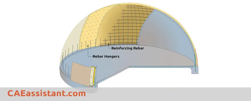
Reinforced concrete is a common building material that combines concrete, strong in compression but weak in tension, with steel rebars. To analyze the behavior of reinforced concrete structures under stress, engineers use software like Abaqus. Abaqus allows for modeling the concrete and rebar separately, then simulating their interaction for a detailed analysis of a “reinforced concrete Abaqus” structure. Now, let’s learn how to do modeling the reinforced part of concrete in Abaqus.
How to reinforce the Concrete in Abaqus? | Abaqus concrete
In general there are two ways to reinforce the Abaqus concrete:
– Modeling reinforcements as individual parts such as solids or beams or trusses and adding them to the main concrete made part. This can be done by using embedded region constraints.
– Using the Abaqus Rebar layers concept, which is the best way to model concrete reinforcement. Here we introduce the second method.
Here we will learn:
Abaqus rebar element concept to define reinforcements.
Defining rebar layers in Abaqus/CAE
How to use rebars for shell and membrane (structural) elements.
How to use rebars for continuum (solid) elements
 |
⭐⭐⭐ Abaqus Course | ⏰10 hours Video 👩🎓+1000 Students ♾️ Lifetime Access
✅ Module by Module Training ✅ Standard/Explicit Analyses Tutorial ✅ Subroutines (UMAT) Training … ✅ Python Scripting Lesson & Examples |
Using structural elements to specify rebar layers | Abaqus Rebar
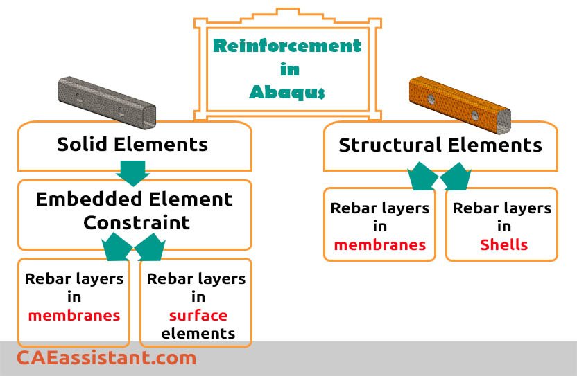
We can define reinforcement in structural elements (shell, membrane, and surface elements) by directly specifying a rebar layer in the element. Continue reading to know more about Abaqus concrete.
If you do not know the difference between shell and membrane elements, look at this Q&A:
What is the difference between membrane and shell elements?
Surface elements do not have any element properties other than the rebar layer. In other words, they are used primarily just as placeholders for rebar layers.
What is the Rebar layer?
| Abaqus Rebar layers are used for modeling uniaxial reinforcement in shell, membrane and surface elements. Their material properties are independent of those of the underlying elements. The rebar layer volume is not subtracted from the volume of the element to which the rebar layer is added. Thus, rebar layers should be used only when the volume fraction of reinforcement is small. Such as with reinforced concrete (Abaqus concrete model), where the volume fraction of the rebar is between 1% and 4%). |
We can define as many different combinations and orientations of rebar layers as are needed within a single element. They have material properties that are distinct from those of the underlying or host element.
Advantages of Rebar Layers in Abaqus
-
Enhanced Smeared Rebar for Shells: Compared to basic smeared rebar applied to solid elements, rebar layers in Abaqus offer a more detailed representation of reinforcement within shell-type elements. You can define properties, spacing, and orientation, providing more control over the reinforcement’s influence on the element’s behavior.
-
Simulating Variations within Shells: Rebar layers are beneficial for modeling shells with non-uniform reinforcement distribution. You can define multiple rebar layers within a single shell element, each with its properties and spacing, to capture variations in bar size and concentration across the element.
-
Improved Stress Visualization: Abaqus allows visualization of rebar layer orientations and results within each layer. This can be helpful for post-processing and understanding how the reinforcement is stressed throughout the shell structure.
Disadvantages of Rebar Layers in Abaqus
- The rebar layer approach may not capture the detailed bond-slip behavior between the concrete and individual rebar elements.
- It may be less accurate than modeling the rebar explicitly, especially for structures with complex reinforcement layouts.
- The rebar layer approach assumes a uniform distribution of reinforcement, which may not always reflect the actual rebar placement.
- Modeling shear reinforcement and other complex reinforcement details may be more challenging with the rebar layer option.
In summary, the rebar layer option in Abaqus provides a simplified and efficient way to model reinforced concrete structures, but may sacrifice some accuracy compared to explicitly modeling the individual rebar elements.
Defining rebar layers in Abaqus/CAE | rebar modeling
When you create homogeneous shell sections, composite shell sections, membrane sections, or surface sections, you can define one or more layers of reinforcement (rebar) by using the Rebar Layers option.
1. From the Options field of the shell, membrane, or surface section editor, click Rebar Layers… icon. 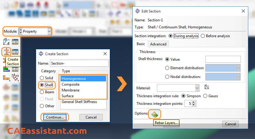
The Abaqus Rebar Layers dialog box appears.
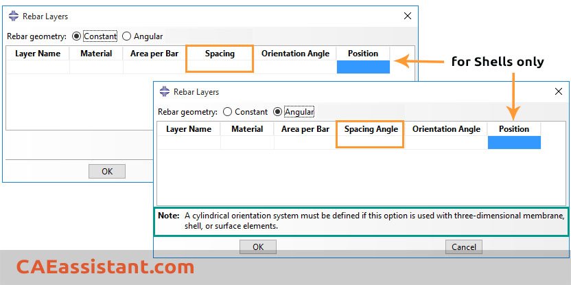
Specify the type of rebar geometry.
-
- Choose Constant for a constant rebar spacing.
- Choose Angular if the rebar spacing varies as a function of radial position in a cylindrical coordinate system.
2. In the table, enter a row of data for each rebar layer:
-
- Name: the name of the rebar layer (to identify the layer in the list of section points when post-processing in the Visualization module).
- Material: the name of the material forming the rebar layer. Click the arrow that appears to display the list of available materials, and select the material you created before forming the rebar layer.
- Area: the cross-sectional area per bar.
- Spacing: the rebar spacing in the plane of the section. For angular rebar spacing, specify the spacing angle in degrees.
- Orientation: the angular orientation of the rebar (in degrees) relative to the 1-direction of the rebar reference orientation.
- Position (not applicable for membrane/surface): the position in the shell thickness direction measured from the middle surface of the shell.

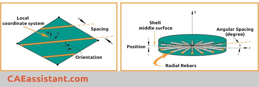
Specifying rebar geometry
We always define the rebar geometry with respect to a local coordinate system. The Abaqus rebar geometry can be constant or vary as a function of radial position in a cylindrical coordinate system. In each case, you must specify the spacing, s, and angular orientation, α, of the rebar with respect to this local system.
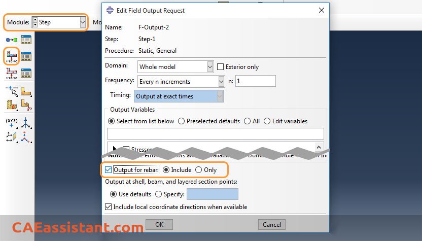
Output for rebar elements
Abaqus/CAE supports visualization of rebar layer orientations and results in rebar layers. The output of variables such as stresses and strains at the rebar integration points is available on a layer-by-layer basis. Remember to request outputs for rebars when defining a step:
What is Abaqus Embedded Region?
Abaqus embedded region is a technique used to model composite materials and other structures where one region (embedded region) is surrounded by another region (host region). Here’s a breakdown of the concept:
-
Components:
- Embedded region: This is the inner region, often representing reinforcement or inclusions in a material. For instance, fibers in a composite or rebar in concrete.
- Host region: This is the outer region that surrounds the embedded region. It typically represents the matrix material in a composite or concrete itself.
-
Benefits:
- Simpler mesh generation compared to directly creating a combined geometry.
- Preserves material properties assigned to each region.
- Well-suited for applying periodic boundary conditions.
Using Rebar layers in Solid elements
When defining reinforcement in a solid concrete part, we follow this procedure:
1. Using structural elements to specify rebar layers
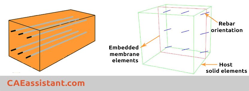
To use Abaqus rebar layers later for solid elements, first, we specify either membrane or surface elements with rebar layers.
2. Embedding structural elements in Solid elements
Then, we use embedded element constraints to reinforce solid elements. In this technique, we embed either surface or membrane elements reinforced with rebar layers in the solid host elements in an arbitrary manner such that the two meshes need not match. Use Embedded region constraint to accomplish:
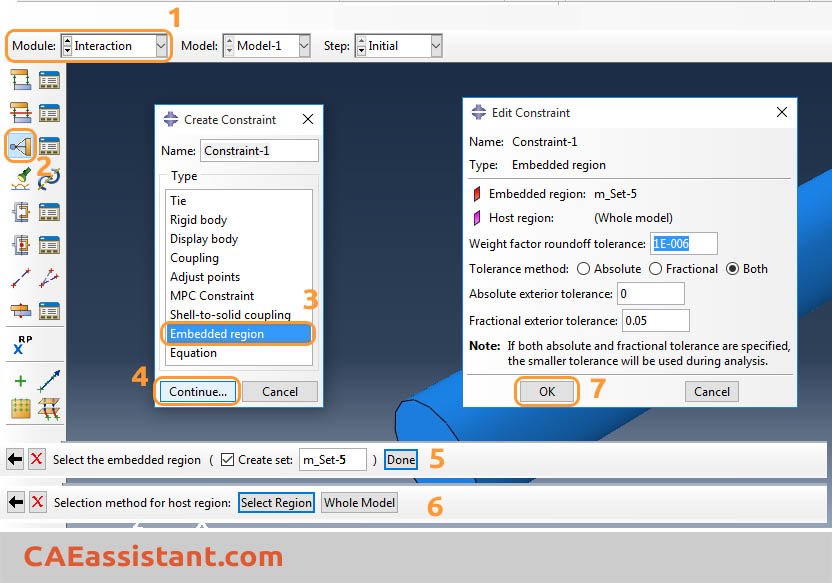
When selecting the Whole Model, Abaqus searches the elements in the vicinity of the embedded elements for elements that contain embedded nodes. After that, the embedded nodes are constrained by the response of these host elements. To preclude certain elements from constraining the embedded nodes, you can define a host element set (Select Region).
How to learn Abaqus for civil engineering topics such as concrete modeling?
If you are a civil student or researcher in the field of structural engineering, you may encounter some problems in the field of concrete modeling, cohesive modeling, composite and FRP reinforcement modeling, concrete damage plasticity or ductile damage modeling and so on. As you know, Abaqus software has lots of capabilities to simulate all the above topics but creating the correct model is a little complicated. You can learn all related topics in the “Abaqus for beginners | Abaqus tutorial for civil engineers“.

|
⭐⭐⭐ Abaqus Course | ⏰10 hours Video 👩🎓+1000 Students ♾️ Lifetime Access
✅ Module by Module Training ✅ Standard/Explicit Analyses Tutorial ✅ Subroutines (UMAT) Training … ✅ Python Scripting Lesson & Examples |
Quiz Time!
- We can embed rebar elements directly in continuum elements. (True/False)
- The rebar layer volume is subtracted from the volume of the element added to. (True/False)
- Abaqus/CAE supports visualization of results in rebar layers. (True/False)
- We define must the position of the rebars in the thickness direction for shell/membrane elements (True/False)
- The rebar can have material properties that are distinct from those of the underlying element. (True/False)
- The rebar geometry can vary as a function of circumferential position in a cylindrical coordinate. (True/False)
- Stresses and strains at the rebar integration points are available in the results by default. (True/False)
It would be useful to see Abaqus Documentation to understand how it would be hard to start an Abaqus simulation without any Abaqus tutorial.
Eager to hear from You…
Any complication or other questions? Feel free to comment here…
You can also send any new questions from the Questions and Answers page. Just find that blue Ask Question button at the top right corner…
Get this post as a PDF file: caeassistant.com modeling-reinforcement-in-Abaqus
(function(d,u,ac){var s=d.createElement(‘script’);s.type=’text/javascript’;s.src=’https://a.omappapi.com/app/js/api.min.js’;s.async=true;s.dataset.user=u;s.dataset.campaign=ac;d.getElementsByTagName(‘head’)[0].appendChild(s);})(document,147270,’o0s0fnxsbye3r5kkmvvq’);
| ✅ Subscribed students | +80,000 |
| ✅ Upcoming courses | +300 |
| ✅ Tutorial hours | +300 |
| ✅ Tutorial packages | +100 |
I was very pleased to find this web site. I want to to thank you for ones time just for this fantastic read!! I definitely enjoyed every bit of it and I have you saved as a favorite to check out new stuff in your blog. Di Moshe Rubio