
3D printing, also known as additive manufacturing, is a process that involves creating three-dimensional solid objects from a digital file. Additive processes are utilized to produce 3D-printed products. In an additive process, the object is constructed by depositing successive layers of material until the final object is formed. Each of these layers can be viewed as a thinly sliced cross-section of the object. Additionally, 3D printing simulation software can assist you in saving a significant amount of money and time. Abaqus additive manufacturing simulation is widely regarded as the optimal approach for achieving the stated objective (details will be discussed later).
With 3D printing, you can create intricate shapes with less material than with other types of manufacturing. 3D printing enables you to produce complex shapes using less material than traditional manufacturing methods.
| Although the term "3D printing," also known as "additive manufacturing," may sound like something out of a science fiction novel; however, the history of 3D printing is much longer than you might think. The technology of 3D printing is a modern marvel. You are mistaken if you thought it really started in recent years. 3D printing has been around for a long time but has only recently become popular. Although 3D printing is older than most people believe, it has grown relatively quickly compared to previous technological advancements. Join us to surprise you with interesting content! |
Printing materials have also changed over time. There is now a wide range of readily available plastics and filaments. Additionally, materials like glass fiber and carbon fiber can be 3D printed. Printing materials like pasta and chocolate are even being used by some creatives!
Because it makes manufacturing more accessible to more people than ever before, 3D printing has gained popularity so quickly. This is partly because of the cost—a basic 3D printer starts at around $300—and also because the printers are smaller than traditional manufacturing processes. But in general, 3D printing is more expensive than traditional methods.
You can see the history of 3D printing in the figure below. In this figure, the progress and application of 3D printing are briefly shown over the years.
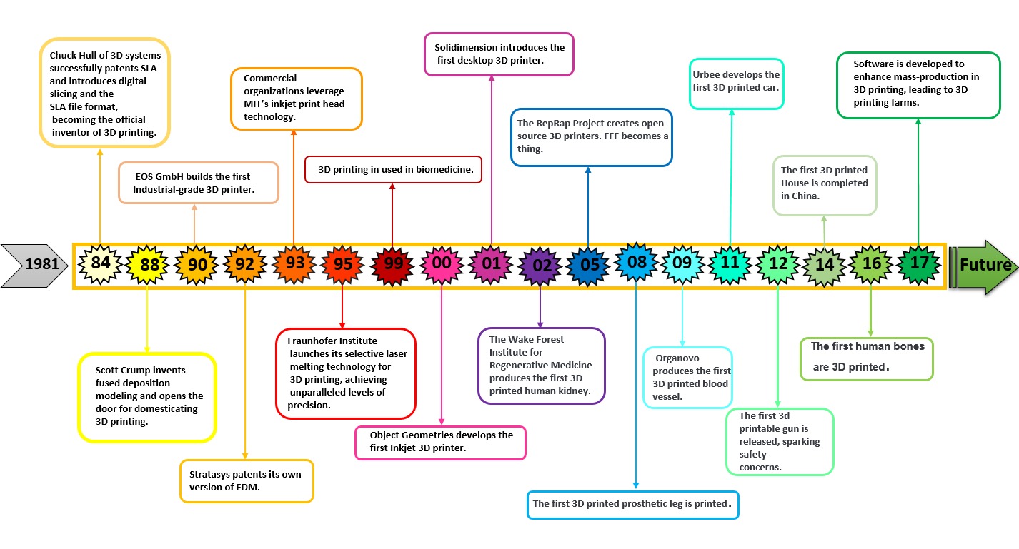
Figure 1: History of 3D printing
In the past few years, as you can see from this figure, 3D printing has become increasingly popular in various industries. This surge in popularity has created a significant demand for 3D printing simulation. Stay with CAE assistant on an exciting exploration of Abaqus additive manufacturing simulation.
1.1. What are the advantages and disadvantages of 3d printing?
One of the most promising technologies among recent innovations is 3D printing because of its advantages. One of the biggest advantages of 3D printing is the additive technology, which opens up a whole new way to make products and has many advantages over traditional manufacturing methods.
Numerous industries benefit greatly from 3D printing. However, it will not substitute for conventional manufacturing. As a result, product designers and manufacturers must view it as an addition to conventional manufacturing. They can use its unique capabilities to improve product design and produce brand-new, impossible-to-make products.
1.1.1. Advantages of 3D printing
When compared to traditional manufacturing methods, this manufacturing process has several advantages. These advantages include those related to design, time, and cost, amongst others.[read more]
Cost reduction
3D printing, as a single-step manufacturing process, saves time and costs associated with using multiple machines for manufacturing. 3D printers can also be set up and left to do their work, eliminating the need for operators to be present the entire time.
Confidentiality
Continuous prototyping and in-house manufacturing with a 3D printer ensure that designs never leave the company premises, protecting your intellectual property. No one else can ever claim your innovations as their own. Every innovative design is kept in-house, so there is no need to be concerned about confidentiality.
Reduce time
3D printing can really make a difference in this situation because we live in a fast-paced world where everything needs to be done quickly. Parts and products can be made much faster with 3D printing than traditional methods, which is a significant advantage. In just a few hours, complex designs can be created as CAD models and made into reality.
This provides design concepts in a way that makes it possible to quickly verify and design them. This is so much better than traditional methods, which can take weeks or months to go from design to prototype and then production.
Reduce errors
When creating products and components, designers must take efficiency into account. Products and parts require numerous traditional manufacturing steps to be produced. As a result, there is a possibility that every step will go wrong, necessitating a new start, which could cause issues with the manufacturing process as a whole. So, it's better for the manufacturing process to be done with just one step.
Production on demand
One major advantage of 3D printing is the ability to design in any shape you want. Additionally, it permits designers to personalize designs. As 3D printing is perfect for one-off productions and building single parts in one process, it means that the ability to customize is there to take advantage of. Therefore,3D printing and design have become increasingly popular in a variety of sectors, including dental and medical. In fact, custom-made parts can be made in a way that has never been seen before, like sporting gear made to fit athletes.
Flexibility
The fact that any printer can produce almost anything that fits within its build volume is yet another significant advantage of 3D printing.
In conventional manufacturing methods, a brand-new tool, mold, die, or jig must be manufactured for each new part or design modification.
In 3D printing, the design is entered into a slicer program, the necessary supports are added, and the design is printed with little to no modification to the actual machinery or equipment.
3D printing permits the creation and production of calculations unthinkable for conventional techniques to deliver, either as a solitary part or by any means. Parts within parts and hollow cavities within solid parts are examples of such geometries.
In contrast to conventional methods, 3D printing permits the combining of various colors, textures, and mechanical properties in a single object by incorporating multiple materials.
Sustainability & Quality
Traditional manufacturing methods can result in poor designs, thus poor quality prototypes. With 3D printing, fewer parts require manufacturing outsourcing. This has a lower environmental impact because fewer items are shipped around the world, and there is no need to operate and maintain an energy-intensive factory.
3D printing produces significantly less waste material for a single part, and the materials used are typically recyclable.[/read]
1.1.2. Disadvantages of 3D printing
Before deciding whether or not to use 3D printing technology, you should remember that it comes with its own disadvantages, just like almost every other process.[read more]
High Energy Consumption
3D printers consume approximately 50 to 100 times more energy when melting plastic with heat or lasers than injection molding, according to research from Loughborough University. Direct laser metal deposition uses 100 times as much electrical energy as traditional manufacturing, according to 2009 studies from The Environmentally Benign Manufacturing, a research group that studies the environmental impacts of product manufacturing. Because of their high energy consumption, 3D printers are better suited for small-scale production runs than for mass production.
3D printing technology is expensive
The price of materials and equipment for 3D printing makes the technology expensive. Because industrial-grade 3D printers still cost hundreds of thousands of dollars, the technology's initial costs are extremely high. Capital expenditures for a single machine can range anywhere from tens of thousands to hundreds of thousands of dollars or more. Additionally, compared to product materials utilized in conventional manufacturing, the materials utilized in commercial-grade 3D printers are pricey.
Limited materials
Although 3D printing represents a significant advancement in manufacturing, the variety of materials that can be utilized is still limited, and some are still developing. Plastic, for instance, is the material of choice for 3D printing. Plastic is preferred because it can be deposited in melted layers quickly and easily to create the final product. However, the strength of plastic may vary, making it unsuitable for some components. Metal is offered as a material by some businesses, but the parts that end up in the products are frequently not fully dense.[/read]
Okay, now that you have the answers to the following questions: "What is additive manufacturing?" and "What are the advantages and disadvantages of this manufacturing method?"
Let's tackle a common question together: "How exactly is a 3D printing simulation done?" Well, the answer depends on the additive manufacturing simulation software you're using, but don't worry; the basic principles are pretty much the same across the board. Let's focus on discussing Abaqus Additive Manufacturing, a popular software for such 3D printing simulations.
The model you want to simulate must be designed in CAD or the FEM software itself; then, the model must be layered in tiny slices and imported into the FEM software; next, the required equations, which describe the material properties variation, boundary and thermal conditions must be applied to the model due to the software settings. And finally, run the simulation. In this post, the 3D printing simulation in Abaqus software will be explained.
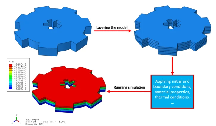
Figure 3: Basics of 3D printing simulation
The 3D printing or additive manufacturing simulation in Abaqus is done via two methods:
- with the use of coding
- Using Abaqus AM Modeler plug-in
2.1. Coding for additive manufacturing simulation
To initiate the Abaqus additive manufacturing simulation, the model must be layered first. It can be done using a CAD software, which is better, or by using the Abaqus itself. Each layer must be printed (activated) in each step; moreover, when a layer is printed, its boundary conditions, material properties, etc, must be applied according to the problem’s equations. These equations describe the material properties variations, thermal conditions, etc. These tasks are divided between python code and the required subroutines. You just need to insert your inputs, run the python code, and wait till the analysis is completed.
Python scripting
The layers of the model must be imported one by one in the Part module. Next, the material properties must be assigned to each layer in the Property module. In the Assembly module, the layers must be piled up and assembled; Also, some geometry sets must be created for further use. Each layer will be printed in a step; for example, if there are six layers, the number of steps would be six. In the Interaction module, the activation of the layers must be set in the right step. The boundary conditions must be defined for each layer in the Load module. And finally, the layers will be meshed and the model is ready. In each module, the required settings must be applied to each layer, separately. Suppose there are hundreds of layers! What are you gonna do then? Apply the settings on each layer one by one!! Don’t you think it’s time-consuming and exhausting?! Simply execute the script, provide some inputs, and wait for the simulation to finish.
Subroutines
The elasticity of 3D printed objects is not constant and changes throughout the process, thus for the proper additive manufacturing simulation it is necessary to use Abaqus subroutines. The subroutine is needed to calculate the elasticity properties according to the equations that describe these changes. Also, a subroutine is needed to compute the temperature variations that occur during the process. The USDFLD and DISP subroutines can be used for these purposes.
Figure 4: 3D printing simulation flowchart using python and subroutine [Ref]
| This method can be used for several 3D printing types such as VAT Photopolymerization (VPP). You can find practical examples in the package below, which happens to include an additive manufacturing simulation of the VPP type. |

Do you think coding is not convenient for additive manufacturing simulation? There is an alternative option called the Abaqus AM Modeler , which provides a graphical interface. Let's explore the details below.
2.2. 3d printing simulation with Abaqus AM Modeler plug-in
Are you looking for 3D printing simulation software or any plug-in that can help you with additive manufacturing simulation?
Abaqus offers an advanced additive manufacturing plug-in as part of its features, which is called “Abaqus AM Modeler”. it is a graphical user interface that offers a comprehensive and scalable solution to simulate 3D printing(3d printing simulation) with minimum risks of making mistakes. You won’t need any python scripting, writing subroutines, or any other coding for this job. Simply just insert the required inputs, create a job, and start the simulation.This Abaqus Additive Manufacturing plug-in(Abaqus AM modeler) performs simulations using two methods:
- Eigenstrain
- Thermomechanical
Each of these methods has several process types, and you can select any of them according to your problem.
The eigenstrain method has two process types: Trajectory-based and Pattern-based.
The thermomechanical method has four process types:
- Trajectory-based powder bed fabrication
- Pattern-based powder bed fabrication
- Laser direct energy deposition
- Fusion deposition modeling
You can simulate common 3D printing types with this plug-in such as Power Bed Fusion (PBF), Direct Energy Deposition (DED), and Material Extrusion (ME).
2.2.1. Eigenstrain
What is the eigenstrain? An engineering concept known as eigenstrain is used to account for all sources of inelastic deformation that result in residual stresses and distortions in manufactured components. It is also known as inherent strain, assumed strain, or "stress-free" strain. Mechanical parts experience residual stresses as a result of almost all manufacturing methods, including additive manufacturing.
A single static stress analysis of a printed part serves as the basis for an eigenstrain analysis of an additive manufacturing process. A predefined field of eigenstrains is then applied to each element upon activation to indicate the inelastic deformation caused by the process. Predicting distortions and residual stresses in the part is the goal of an eigenstrain analysis. Applying eigenstrains to a newly formed layer can cause residual stresses and distortion in the layers below. A thermal-stress analysis typically yields a more precise result than an eigenstrain analysis. Nonetheless, an eigenstrain analysis frequently takes less time to run because just a static procedure is needed.
In the figure below, there is an example of an additive manufacturing process of a two-layer build with the eigenstrain method:
- The first layer is added.
- The first layer is unconstrained—it contracts when negative eigenstrains are applied.
- The second layer is added on top of the first layer and bonded to the first layer.
- The contraction of the second layer is constrained by the bonding of the first layer, causing the part to distort and inducing residual stresses.
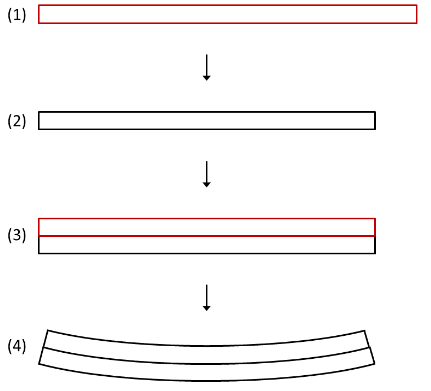
Figure 5: Distortion due to eigenstrains in a two-layer additive manufacturing process [Ref]
Trajectory-Based Eigenstrain Analysis
The activation of elements and application of eigenstrains in a trajectory-based eigenstrain analysis is specified by a defined trajectory of new material being fused or bonded to the underlying layer.
Pattern-Based Eigenstrain Analysis
A pattern-based eigenstrain analysis applies eigenstrain based on a predetermined in-plane eigenstrain pattern for each layer, activating elements layer by layer.
So, as we mentioned, mechanical parts experience residual stresses as a result of additive manufacturing. Therefore, it is important to consider this concept during additive manufacturing simulation using the eigenstrain method. It should be noted that we didn't consider the thermal aspects of 3D printing. On the other hand, the thermomechanical method is a more comprehensive approach that takes into account both the thermal and mechanical aspects of the additive manufacturing simulation. Let's see how this method works!
2.2.2. Thermomechanical
This method is a sequential thermal-stress analysis of an additive manufacturing process. It means a heat transfer analysis must be done first; then, a static structural analysis is done and the results of the thermal analysis, which are temperature fields must be applied to it. The simulation provides you precise control over the fidelity of the solution and allows you to specify processing conditions precisely in both time and space. Although the simulation is thorough and realistic, it can become computationally expensive as time and spatial (mesh) resolution increase.
The following aspects of the procedure must be simulated for the heat transfer analysis:
- Progressive material deposition: every AM process adds new material over time.
- Progressive heating of the deposited material: In some additive manufacturing techniques, the deposited material is heated until it melts, causing the material to fuse to a substrate or an underlying layer.
- Progressive cooling of the printed part: A part's cooling surface changes over time as it is printed.
For stress analysis:
- The stress analysis is driven by the temperatures from the heat transfer analysis.
- It is possible to apply progressive material deposition methods that are comparable to heat transfer analysis.
- For precise stress results, temperature-dependent material properties can be used.
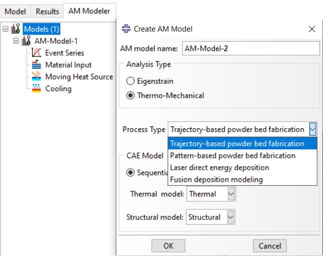
Figure 6: Abaqus AM Modeler plug-in
If you are working in this field and are eager to quickly and comprehensively learn Abaqus additive manufacturing simulation, I strongly recommend checking out the package below, provided by the experts at CAE Assistant.
Great! So far, we've covered the definitions of 3D printing, the advantages and disadvantages of additive manufacturing, additive manufacturing simulation software (Abaqus), and an introduction to the two main methods of 3D printing simulation: Abaqus AM Modeler and coding. Now, let's shift our focus to exploring the various types of additive manufacturing.
3D printing refers to a group of manufacturing technologies that build parts layer by layer. Material selection, surface finish, durability, manufacturing speed, and cost can all be different between them. The seven main types of 3D printing are as follows:
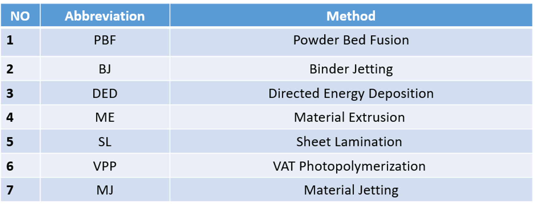
Figure 7: The seven main types of 3D printing
| You may be wondering how to utilize a 3D printing simulation software like Abaqus to simulate your own 3D printing method. We have provided a brief explanation of this, so please stay with us. |
You can see the 3D printing category in figure 8.
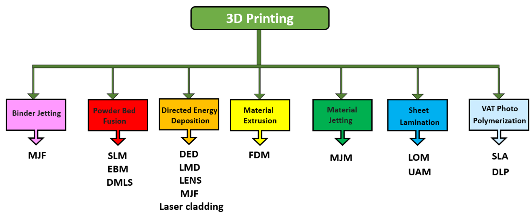
Figure 8: 3D printing category
The recognition of 3D printing could help us have a comprehensive view of Abaqus additive manufacturing simulation, allowing us to simulate with a better understanding. We have explained all the 3D printing methods one by one, so let's take a look at the first one: Powder Bed Fusion Definition.
3.1. What is powder bed fusion? | Powder Bed Fusion Definition
Powder bed fusion (PBF) methods melt and fuse the material powder using either a laser or an electron beam. Electron beam melting (EBM) methods require a vacuum but can be used to create functional parts from metals and alloys. The powder material is spread over previous layers in all PBF processes. The powder-based method is one of the most important and widely used types of 3D printing. The powder material's high reusability rate, quick production speed, strong functional parts, low cost, lack of or minimal support structures, numerous application areas, and wide range of compatible materials are some of the reasons for its widespread use
Application of this method in the industry: PBF is being studied extensively and used in various industries, including the aerospace, automobile, medical, and energy sectors.
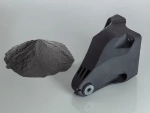
Figure 9: Industrial part produced by Powder Bed Fusion method [Ref]
Powder Bed Fusion – Step by Step:
What is Powder Bed Fusion process? You can find the answer in the figure below.
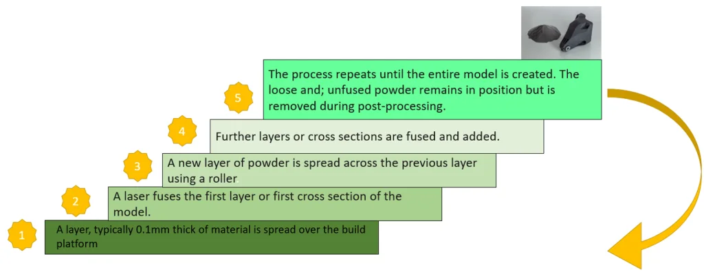
Figure 10: Powder Bed Fusion steps
Material: The Powder bed fusion process uses powder-based materials, but common metals and polymers are shown in figure 11.
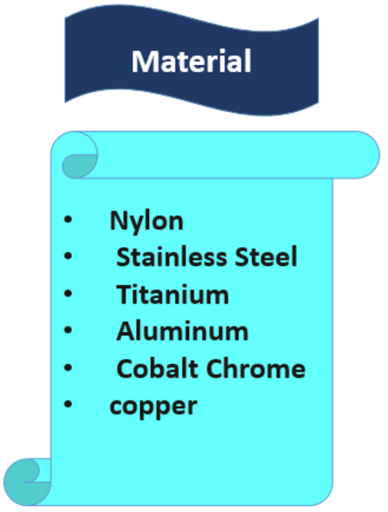
Figure 11: Powder Bed Fusion materials
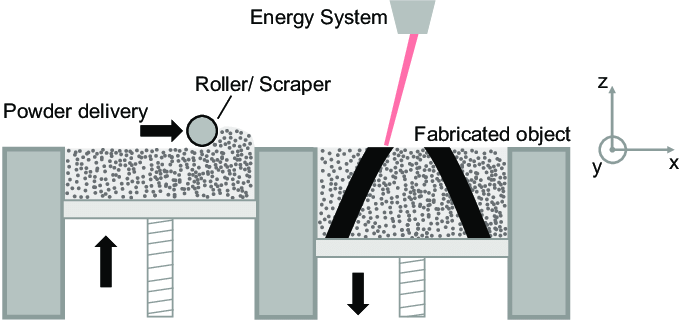
Figure 12: Schematic image of Powder Bed Fusion method device [Ref]
Now the question is: What is the Powder Bed Fusion technique? I must clarify that there isn't just one technique; instead, there are several techniques involved. Direct Metal Laser Sintering (DMLS), Electron Beam Melting (EBM), Selective Heat Sintering (SHS), Selective Laser Melting (SLM), and Selective Laser Sintering (SLS) are all common printing techniques used in the Powder Bed Fusion process.
Great! Now that we have covered some information on the Powder Bed Fusion definition, let's move on to discussing how we can simulate this method.
3.1.1. 3d printing simulation with powder bed fusion method
The simulation of the PBF method in Abaqus can be done via the Abaqus AM Modeler plug-in with the thermomechanical analysis type, which has two process types: Trajectory-based powder bed fabrication and Pattern-based powder bed fabrication.
Trajectory-based powder bed fabrication
An event series in the form of a table of time, spatial coordinates, and process parameters can be used to represent the time-location history of the heating source (laser beam scanning path) and both the sequence of material deposition (recoater motion). The event series data is fed into the toolpath-mesh intersection module, which automatically computes all the information necessary to activate the elements and apply the correct thermal energy to the model. To describe extra process parameters required for the simulation, table collections that encompass parameter tables or property tables can be employed.
| Would you like to explore the intricacies of the powder bed fusion definition? Are you interested in simulating powder bed fusion 3D printing? Take a look at this package where we provide all the necessary information. |
[read more]Selective Laser Melting (SLM)
Selective Laser Melting (SLM) machines make up the majority of Powder Bed Fusion machines. High-powered lasers are used in SLM machines to fuse metal layers into parts. After a print, the part is cut out of the build plate, removed from the powder bed, and post-processed by an operator. Most Metal AM-based businesses currently offer SLM machines, making it the industry standard for metal printing.
Electron Beam Melting (EBM)
Electron Beam Melting (EBM) is a three-dimensional manufacturing technique in which an electron beam of high energy melts the metal powder. An electron beam creates a stream of electrons that melt layer upon layer of powdered metal guided by a magnetic field to produce an object that meets the exact specifications of a CAD model. Production takes place in a vacuum chamber to prevent oxidation, which can compromise highly reactive materials. Selective Laser Melting (SLM) and Electron Beam Melting (EBM) both print from powder on the powder bed of a 3D printer, but EBM employs an electron beam rather than a laser. EBM machines, like SLM, are expensive to set up and require a dedicated technician to operate.
Selective laser sintering (SLS)
A powder-based 3D printing technique called Selective Laser Sintering (SLS) uses a laser to fuse material layers into a final part. A bed of powder is traced by the laser with the pattern of each cross-section of a three-dimensional design. The build platform descends after constructing one layer, and another layer is built on top of the first one. This procedure continues until each layer is constructed and the component is finished.
Direct metal laser sintering (DMLS)
The industrial metal 3D printing process known as direct metal laser sintering (DMLS) produces fully functional metal prototypes and production parts in a few days.
A laser is directed by a digitally produced CAD (computer-aided design) file at the powder bed at specific points in space to create each layer of a part in this method. After printing a layer, the machine spreads more powder over the part and repeats the process. Printing precise, high-resolution parts with intricate geometries is a breeze with this method. DMLS machines utilize a laser to warm the particulate, making a difference in the dissolving point in a computerized cycle that removes the requirement for actual molds. The finished products are precise, have near-wrought mechanical properties, and have excellent surface quality.
DMLS machines are efficient but notoriously difficult to purchase and use. They require powder management, supporting machines like EDM machines, and skilled operators. Machines frequently require a process of trial and error before producing accurate and functional parts due to the process's high energy.[/read]
Sure, I believe you now have a good overview of the definition of powder bed fusion(powder bed fusion definition), or in other words, the answer to our main question, "What is powder bed fusion?" Therefore, I think it's time to move on to discussing binder jetting additive manufacturing.
3.2. Binder Jetting additive manufacturing
The process of depositing an adhesive binding agent onto thin layers of powdered material is known as binder jetting in 3D printing. Metal (like stainless steel) or ceramic-based (like glass or gypsum) is the powdered material.
The production of large sand casting cores and molds, low-cost 3D printed metal parts, and full-color prototypes (like figurines) are just a few examples of the many applications for Binder Jetting.
Because there are so many different uses for Binder Jetting, it is essential for a designer to understand the fundamental mechanics of the process and how these relate to the main benefits and drawbacks of this method.
Application of Binder Jetting additive manufacturing in the industry: Binder jetting can be used in a wide range of applications and industries, including architecture, aerospace, art and design, and automotive.
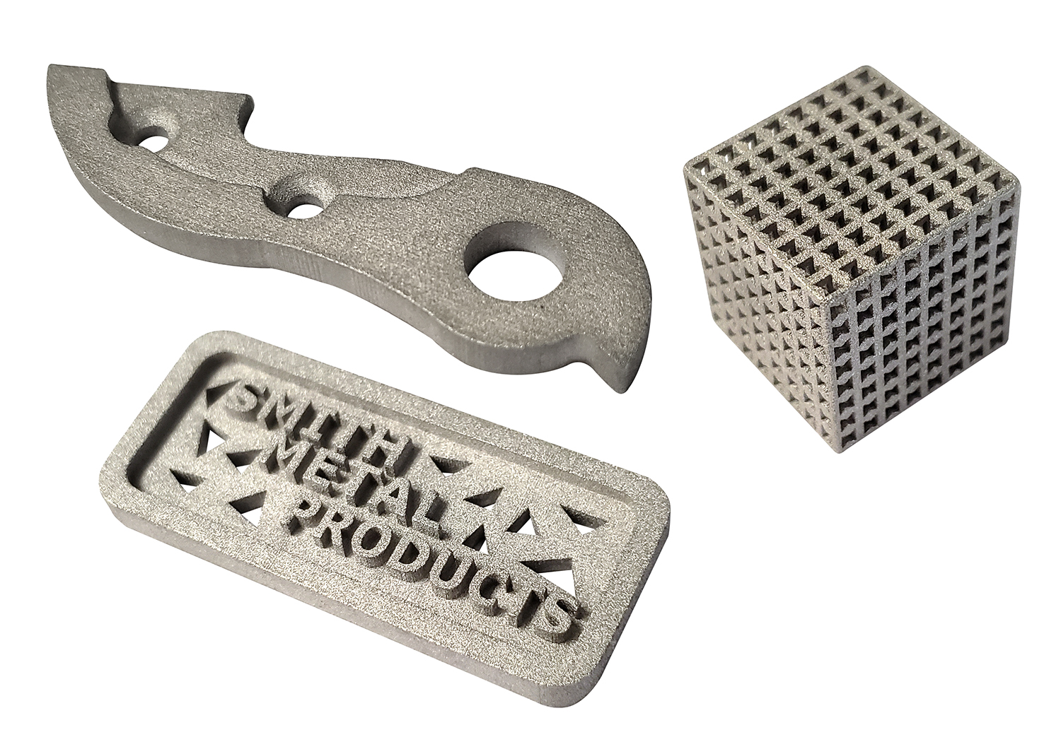
Figure 13: Industrial parts produced by the Binder Jetting method [Ref]
Binder Jetting – Step by Step:
Take a look at the figure below to get a glimpse of the binder jetting additive manufacturing process.
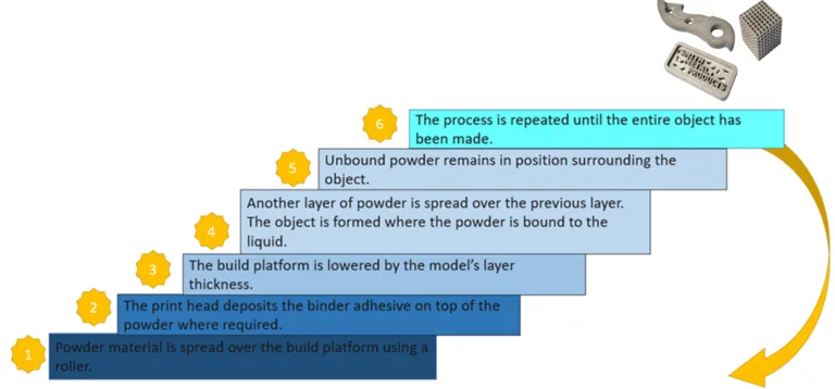
Figure 14: Binder Jetting steps
Material:
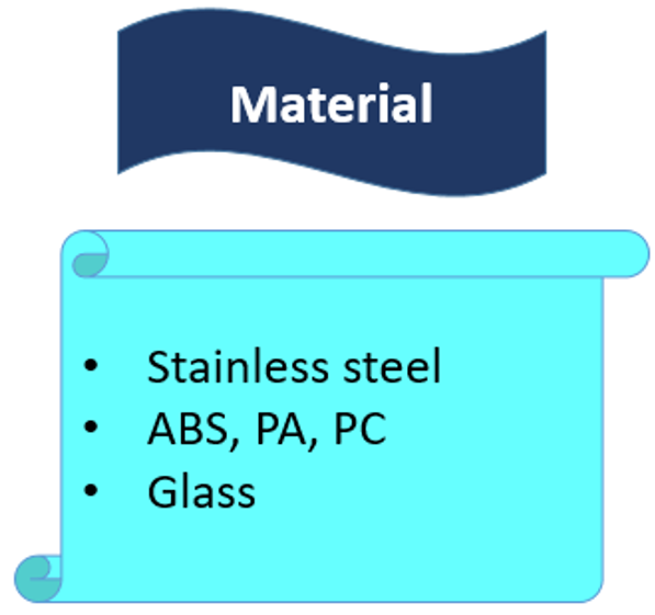
Figure 15: Binder Jetting materials
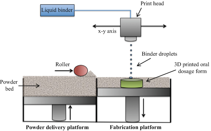
Figure 16: Schematic image of Binder Jetting method device [Ref]
[read more]Multi Jet Fusion (MJF)
The industrial 3D printing process, Multi Jet Fusion, can produce functional nylon prototypes and production parts for end use in as little as one day. Compared to processes like selective laser sintering, final parts have superior surface finishes, fine feature resolution, and more consistent mechanical properties.[/read]
3.3. Direct Energy Deposition additive manufacturing
Direct energy deposition uses a laser and metal feedstock to produce parts. The stock, which can be wire or powder, and the laser both sit on a single print head that simultaneously dispenses and fuses material, in contrast to powder bed fusion. With a few key differences and opportunities, the resulting components are very similar to those produced by Powder Bed Fusion. (3D printing simulation)
Application of Direct Energy Deposition additive manufacturing in the industry:
Aerospace, defense, oil & gas, and the marine sector already make use of DED for things like aircraft frames and structures, refractory metal components, ballistic material tooling repair and reconditioning, and marine propulsion, among other things.
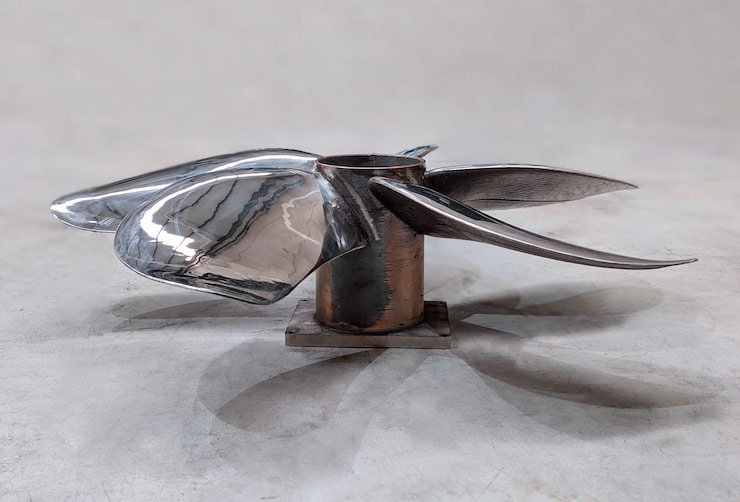
Figure 17: Industrial part produced by Direct Energy Deposition method [Ref]
Direct Energy Deposition – Step by Step:
Just like before, you can check out the figure below to see the direct energy deposition additive manufacturing process.
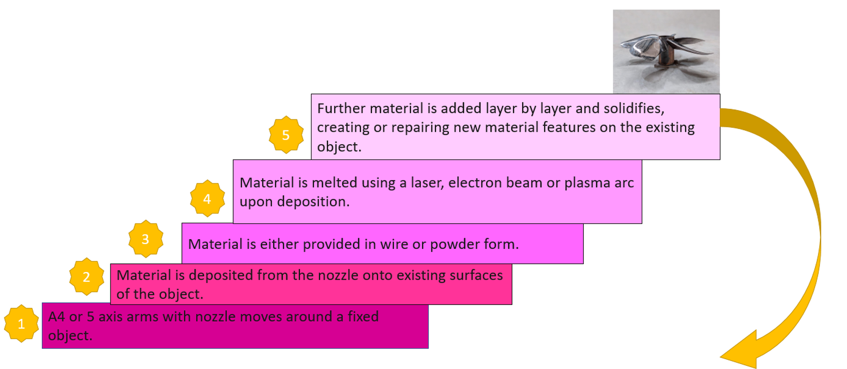
Figure 18: Direct Energy Deposition additive manufacturing steps
Material:
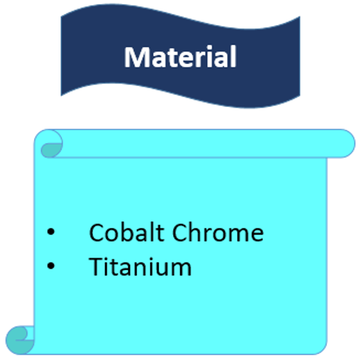
Figure 19: Direct Energy Deposition materials
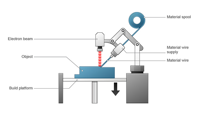
Figure 20: Schematic image of the Direct Energy Deposition method device [Ref]
3.3.1. DED simulation in Abaqus
The simulation of the DED method in Abaqus is done via the Abaqus AM Modeler plug-in with the thermomechanical analysis. The simulation procedure of the DED and ME types is the same. In a structural analysis or a thermal analysis, progressive element activation is used to model the deposition of raw material from a moving nozzle. Any form, such as a rectangle or circle, can be used for the cross-section of the nozzle and the bead of material being deposited. More info is in the FDM simulation in Abaqus.
[read more]Powder DED
Powders result in lower deposition efficiency compared with metal wires, as only a part of the total powder would be melted and bonded to the substrate. DED machines precisely blow powder out of a print head onto a part and use an on-head laser to fuse it to the part in construction instead of spreading powder on a bed and melting it with a laser.
Wire DED
Similar to their powder DED relatives, wire DED machines melt feedstock with a laser, but their feedstock is metal wire rather than blown powder. It is a special technology used for larger build volumes (up to 5 meters by 1 meter by 1 meter) and faster print times, but it sacrifices precision and quality. Consequently, powder bed machines' wire DED parts are designed to be significantly larger and less precise. These machines are extremely uncommon in the area and cost several million dollars per unit.
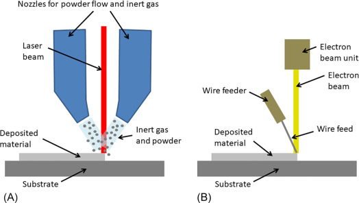
Figure 21: Schematics of two DED systems (A) uses laser together with powder feedstock and (B) uses an electron beam and wire feedstock [Ref]
Laser Engineered Net Shaping (LENS)
In contrast to SLM, which employs a powder bed, the LENS method involves injecting powder into a nozzle and irradiating a laser beam with a high energy density to melt and deposit the component layer by layer over a built base plate. The build platform gradually descends after each layer has been deposited. This interaction rehashes until a normal part is understood.
Multi Jet Fusion (MJF)
The printer applies a layer of material powder to the printing bed during the Multi Jet Fusion printing process. Following this, a fusing and detailing agent are applied to the powder by running an inkjet head across it.
The print is then heated with an infrared heater. The underlying layer "melts" together wherever a fusing agent is added, but the detailing agent-exposed areas remain as a powder. The desired geometry is achieved when the powdery parts fall off. Because the layers below them support those printed above them, this generally means that supports are not required.
Laser cladding
Laser cladding is an added substance-producing process where a laser shaft is utilized to locally dissolve the outer layer of the base material, and an added substance material, normally in powder structure, is all the while added to the subsequent liquefy pool. The relative movement of the cladding head toward the coating causes the melt to solidify.[/read]
3.4. Material Extrusion | Extrusion-based 3d printing
Material extrusion or extrusion-based 3d printing is an additive manufacturing (AM) process that builds 3D parts layer by layer out of thermoplastic or composite materials. The fiber is taken care of from a spool through a warmed expelling spout, which warms the material and stores it in a formative stage.
Material extrusion is the most widely used 3D printing method for hobby-grade home use, despite its lack of accuracy or speed compared to other additive manufacturing processes. Material extrusion is used for rapid prototyping in an industrial setting.
Material expulsion added substance producing innovation includes taking care of a persistent fiber of thermoplastic or composite material through an expelling spout to build 3D parts.
Application of Extrusion-based 3d printing in the industry:
Material extrusion is frequently utilized in low-cost home and hobby 3D printers, but it is also utilized in more industrial settings for constructing buildings through concrete extrusion or producing human tissues and organs for medical use.
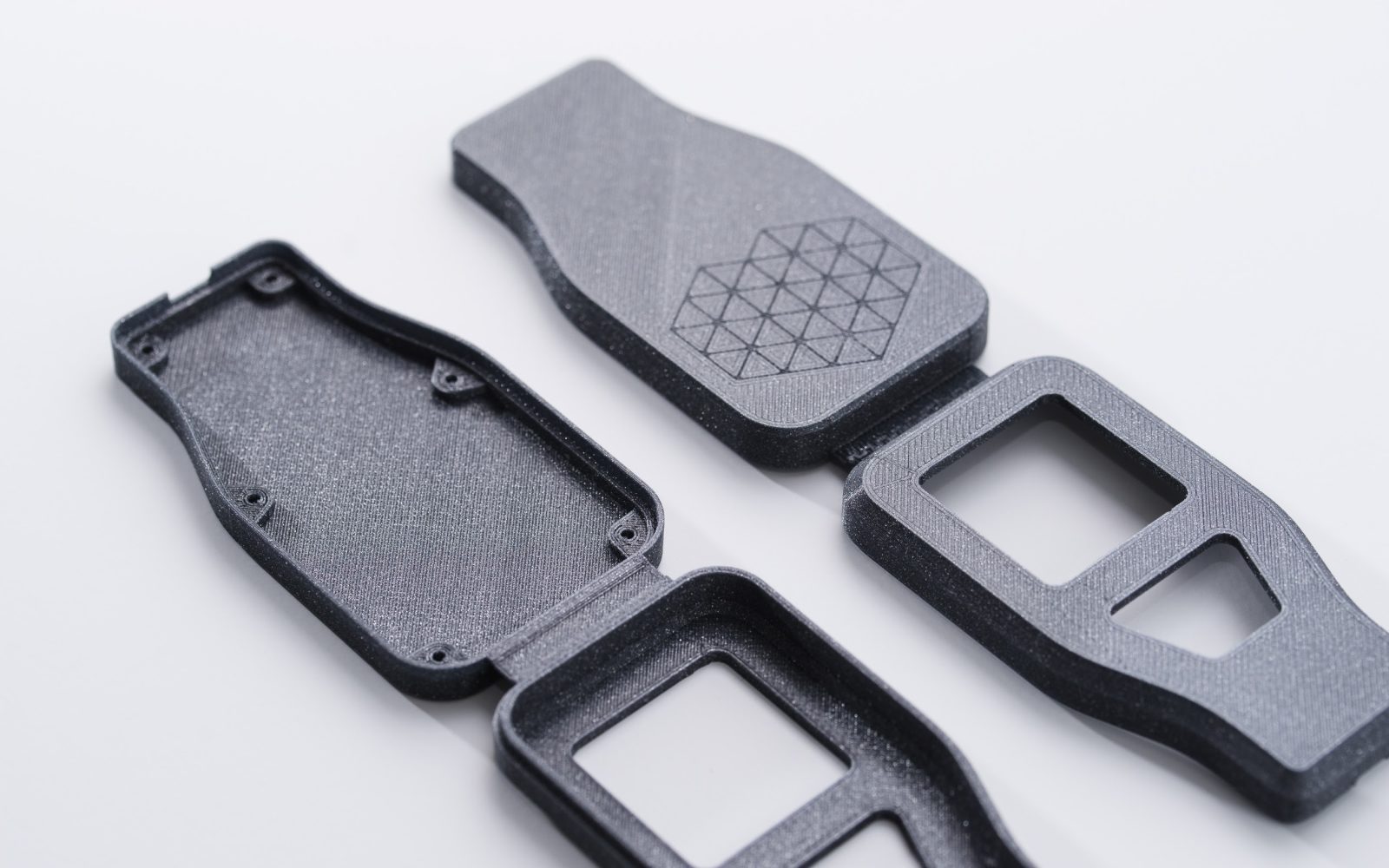
Figure 22: Industrial parts produced by Material Extrusion method [Ref]
Extrusion-based 3d printing– Step by Step:
In the figure below, you can observe the straightforward process of extrusion-based 3D printing. The initial layer is deposited by the nozzle, and subsequent layers are added on top and fused together. This gradual layering and fusion result in the creation of the final 3D object.
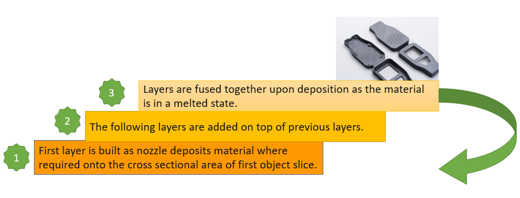
Figure 23:Extrusion-based 3d printing steps
Material:
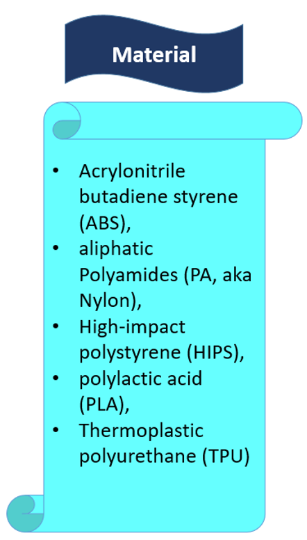
Figure 24: Material Extrusion materials
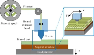
Figure 25: Schematic image of the Material Extrusion method device
Fused deposition modeling (FDM)
Fused deposition modeling, or FDM for short, is an additive manufacturing technique for extruding materials through a nozzle to form three-dimensional objects.
The "standard" FDM process stands out from other methods for extruding materials, like concrete and food 3D printing, by using thermoplastics as its feedstock, usually in the form of pellets or filaments.
Therefore, a typical FDM 3D printer pushes a polymer-based filament through a heated nozzle, melting the material and depositing it in two-dimensional layers on the build platform. These layers eventually fuse together to form a three-dimensional part while they are still warm.
3.4.1. FDM simulation in Abaqus
As mentioned earlier, the material extrusion (FDM) type and the DED have the same simulation procedure in the Abaqus.
Here is the short version of this procedure:
The element activation (deposition of raw material) is done, gradually. The path of the nozzle is defined by an event series. The required settings in the plug-in must be specified for the material deposition, which you can see in figure 26. Next, the thermal energy used to heat the bead to the melting point will be applied when the bead is deposited (activated element). This energy can be distributed over the activated elements in different ways concentrated, uniform, and Goldak.
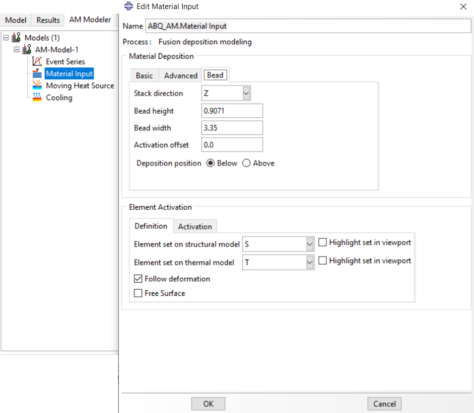
Figure 26: material deposition settings in Abaqus AM Modeler
Each of the tiny bars or strands that are deposited from the nozzle to form the object is called the “bead”; it can have a circular or rectangular shape. See figure 28 for a better understanding. And finally, the cooling process will be done by the conductivity and radiation heat transfer.
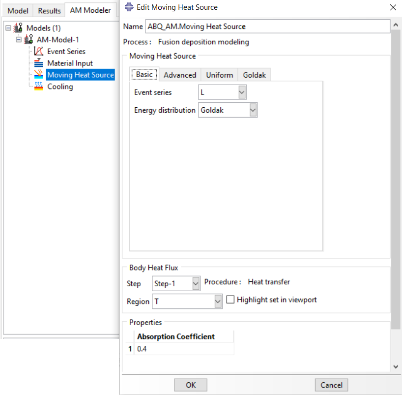
Figure 27: applying heat source settings
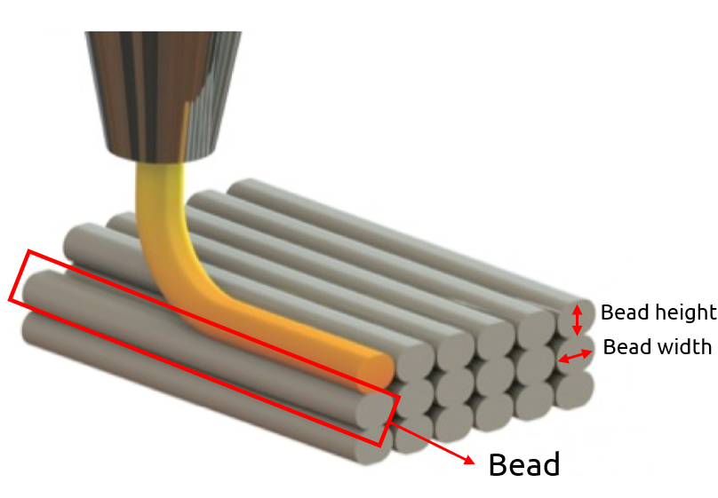
Figure 28: bead definition
| As you have obtained answers to your common questions like: what is additive manufacturing?, pros and cons, types of additive manufacturing, etc. I highly recommend immersing yourself into becoming proficient in 3D printing simulation software, specifically Abaqus. To achieve this, I suggest utilizing the practical package provided below: |
3.5. Sheet Lamination additive manufacturing
In order to produce an object, the Sheet Lamination (SL) 3D printing process, also known as Laminated Object Manufacturing (LOM), involves super positioning several layers of foil-based material. Using a knife or laser, the operator shaped each foil to fit the object's cross-section.
Application of this method in the industry: Ergonomics studies, topography visualization, and architecture models for paper-made objects are some of the applications for parts made with 3D laminated objects. Fibers and thermoplastics make it possible to directly manufacture cost-effective, lightweight technical parts for the aerospace and automotive industries.
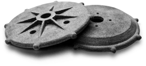
Figure 29: Industrial parts produced by Sheet Lamination method [Ref]
Sheet Lamination – Step by Step:
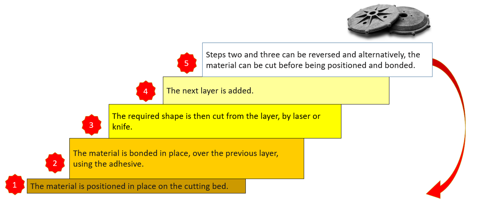
Figure 30: Sheet Lamination steps
Material:
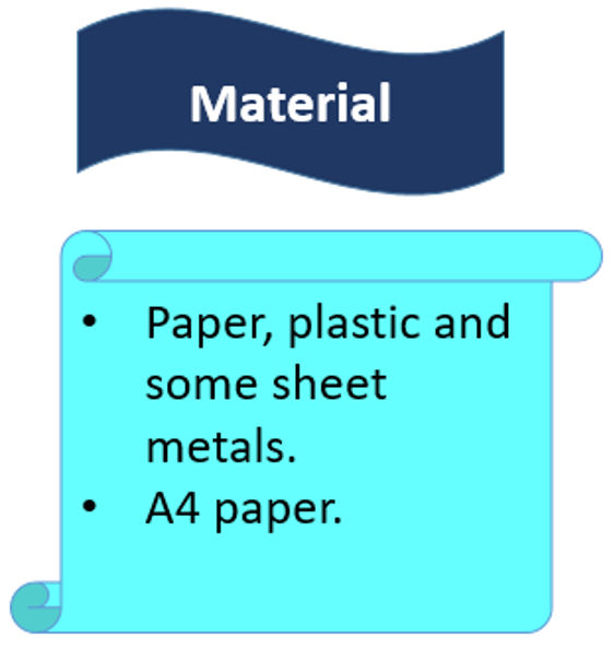
Figure 31: Sheet Lamination materials
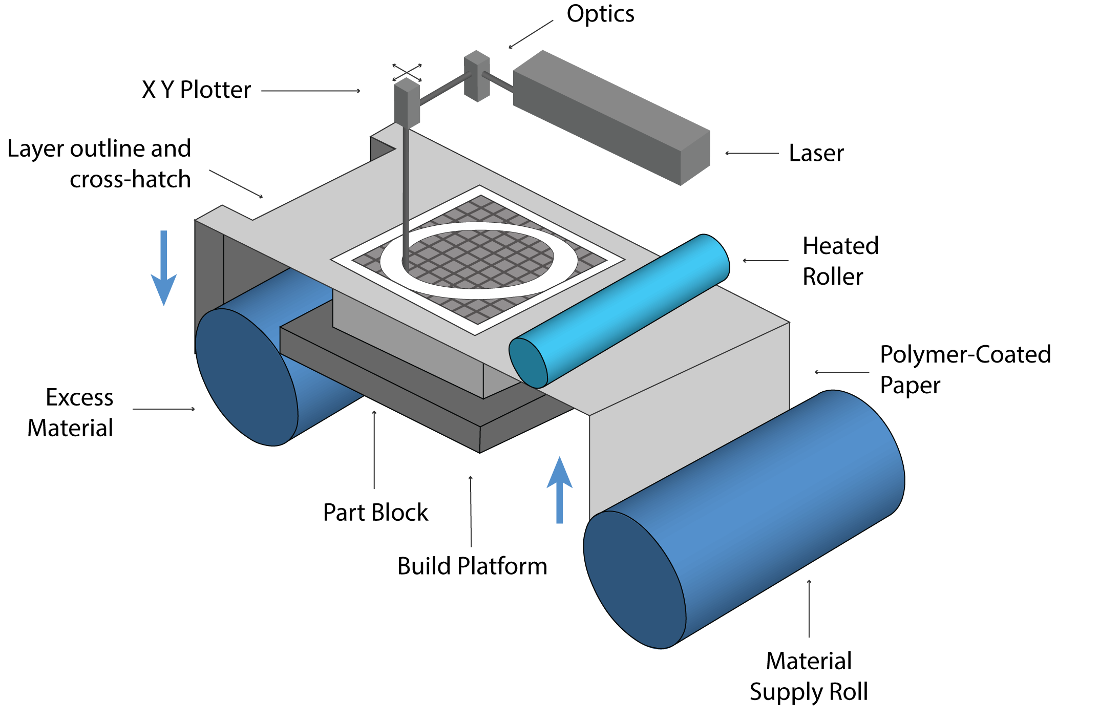
Figure 32: Schematic image of the Sheet Lamination method device [Ref]
[read more]Laminated object manufacturing (LOM)
LOM is a fast and inexpensive additive manufacturing process that is typically used for rapid prototyping rather than production. The finished object's precision is determined by the thickness of the material layers used, but it is typically less precise than other methods.
Ultrasonic additive manufacturing (UAM)
A hybrid sheet lamination process that combines ultrasonic welding and computer numerically controlled (CNC) milling is known as ultrasonic additive manufacturing (UAM) or ultrasonic consolidation (UC).[/read]
Okay, let's change the topic, what is additive manufacturing: VAT Photopolymerization method ?
3.6. VAT Photopolymerization additive manufacturing
UV light is used to solidify photo-sensitive resin in a process called photopolymerization. It is utilized by a variety of 3D printing procedures, including Stereolithography (SLA), MultiJet printers, and 3D Digital Light Processing (DLP). In both academic and commercial research settings, the field of 3D printing continues to grow rapidly. Photopolymerization-based processes, which use adaptable polymer chemistry, offer flexibility over the materials' final properties compared to other 3D printing methods.
Application of this method in the industry: Surgical learning tools, facial prosthetics, and hearing aids are among the most common applications in the medical and dental fields. Vat photopolymerization can also be used to make molds for low-volume injection molding.
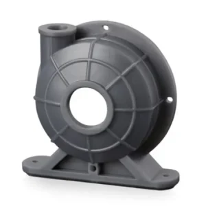
Figure 33: Industrial part produced by VAT Photopolymerisation method [Ref]
VAT Photopolymerisation – Step by Step:
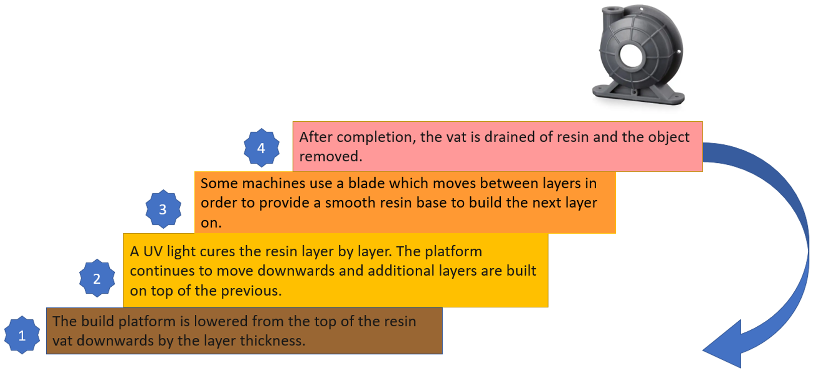
Figure 34: VAT Photopolymerisation steps
Materials: The Vat polymerization process uses Plastics and Polymers.
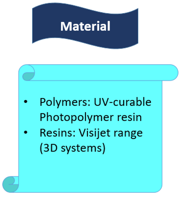
Figure 35: VAT Photopolymerisation materials
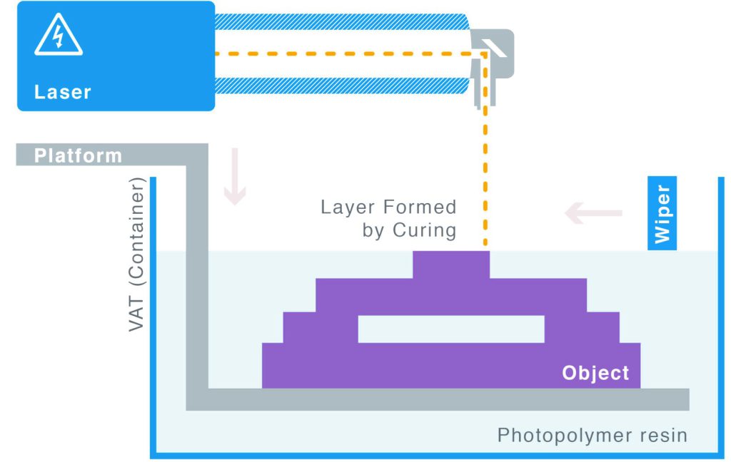
Figure 36: Schematic image of VAT Photopolymerisation method device [Ref]
Stereolithography (SLA)
Stereolithography (SLA) is a commercial 3D printing method that can produce concept models, cosmetic prototypes and intricately shaped parts in as little as one day. SLA allows for a wide range of materials, extremely high feature resolutions, and high-quality surface finishes.
Because SLA is all about precision and accuracy, it is frequently utilized in situations where form, fit, and assembly are crucial. SLA provides the smoothest surface finish of any additive manufacturing process, and the tolerances on SLA parts are typically less than 0.05 mm. Due to the quality that SLA can achieve is especially useful for making functional prototypes, presentation models, form and fit testing, and highly precise casting patterns (such as injection molding, casting, and vacuum casting). SLA technology is extremely adaptable and can be utilized in various settings where precision is of the utmost importance.[read more]
Digital Light Processing (DLP)
DLP is a 3D printing (additive manufacturing) technique that creates solid products and parts by combining light and liquid resin. DLP and its applications will be discussed in this article.
DLP 3D printers, as you already know, make use of resin-based liquid photopolymers. There are a lot of different resins and prices to choose from. However, the conventional general approximation is always available.[/read]
3.6.1. Stereolithography simulation in Abaqus
The simulation of the SLA method can be done with the first method, which is using python scripting and subroutines. The short version of the procedure was explained in section 2.1.
3.7. Material Jetting 3d printing
Material jetting is similar to a two-dimensional inkjet printer in that it produces objects. A continuous or Drop on Demand (DOD) method is used to jet material onto a build platform.
The model is constructed layer by layer after the material is jetted onto the build surface or platform, where it solidifies. A nozzle that moves horizontally across the build platform deposits the material. The complexity of machines and how they control material deposition vary. After that, ultraviolet (UV) light is used to cure or harden the material layers.
The number of materials that can be used is limited because the material must be deposited in drops. Due to their viscosity and capacity to form drops, polymers, and waxes are suitable and frequently utilized materials.
Application of material jetting 3d printing in the industry:
Material jetting technologies are used in a wide range of industries, including medical, engineering, aerospace, and jewelry.
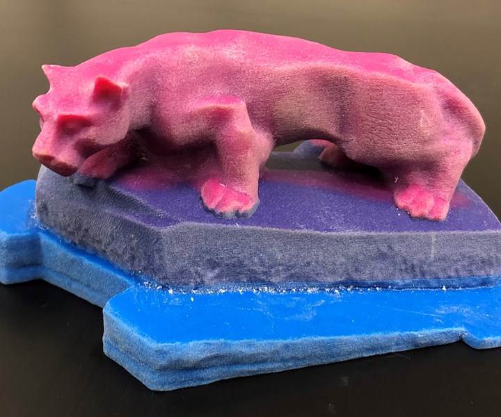
Figure 37: Industrial part produced by Material jetting method [Ref]
Material Jetting – Step by Step:
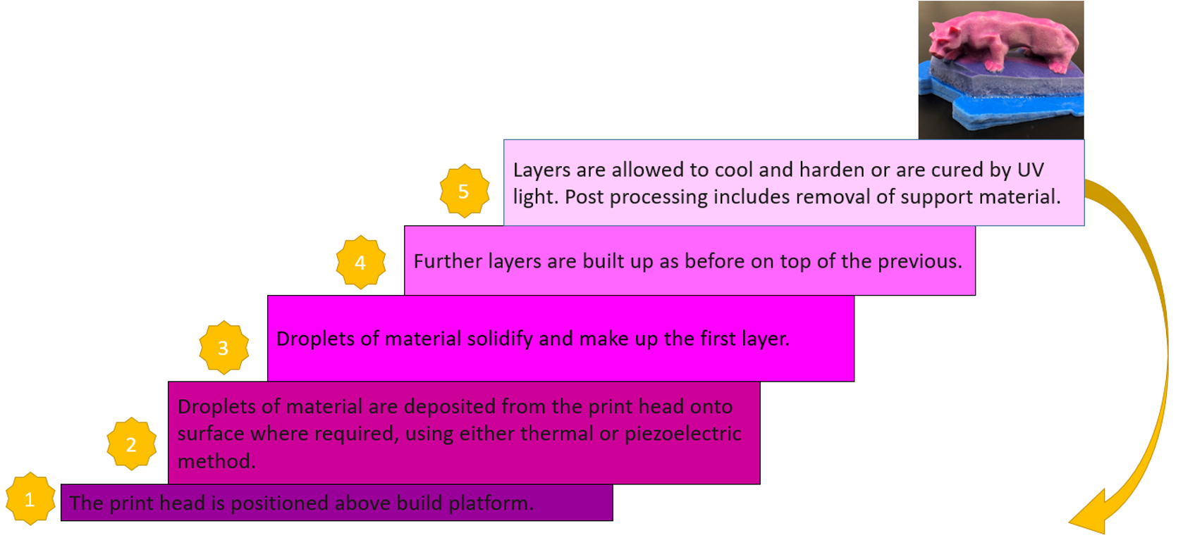
Figure 38: Material Jetting steps
Materials: The material jetting process uses polymers and plastics.
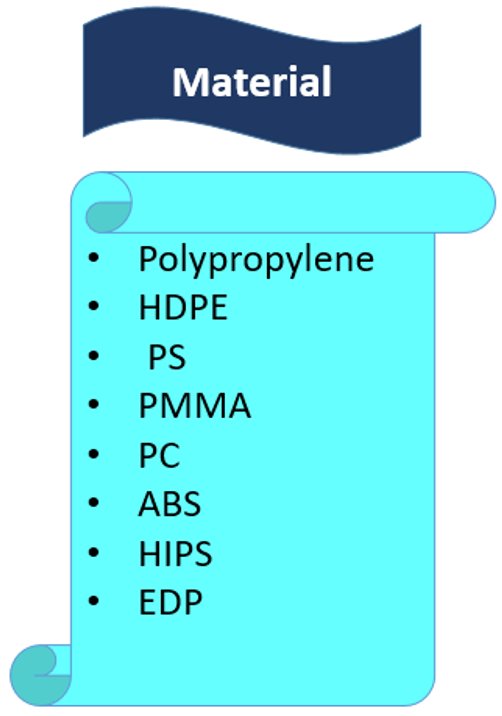
Figure 39: Material Jetting materials
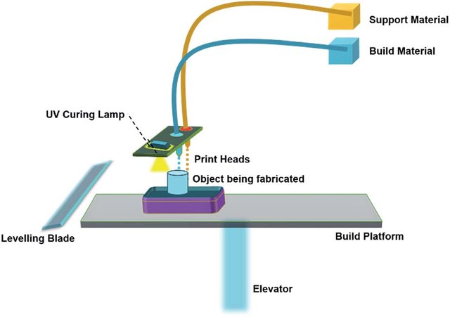
Figure 40: Schematic image of the Material jetting method device
[read more]PolyJet
PolyJet is a powerful 3D printing technology that makes parts, prototypes, and tooling that are smooth and accurate. It can produce thin walls and complex geometries using the widest range of materials that are available with any technology, with microscopic layer resolution and accuracy down to 0.014 mm. PolyJet is a 3D printing technique that creates parts by solidifying thousands of photopolymer droplets with a UV light on a build platform. It is currently one of the technologies for 3D printing that is both the fastest and most accurate.
Multi-Jet Modeling (MJM)
Multi Jet Modelling (MJM) uses a print head with multiple nozzles to apply tiny droplets of material to a printing plate. UV light immediately hardens the liquid polymer, enabling the production of the desired components layer by layer. It is possible to reproduce extremely fine details because the applied droplets are so minute. In addition, the surface becomes extremely smooth before the curing process begins. Overhanging components require support structures during printing.
The desired parts can be printed directly in multiple colors using multiple print heads in the MJM 3D printing process. There are also materials that are translucent and let light through. Material and color gradients are also possible because the material is applied with small droplets.[/read]
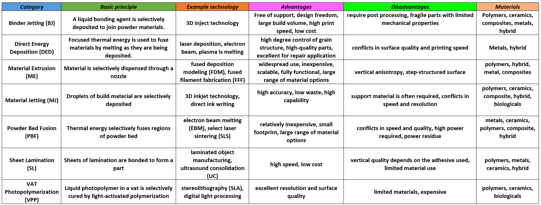
The following table briefly shows the advantages and disadvantages of the types of additive manufacturing.
So far, we have answered a variety of questions related to 3D printing, such as "What is additive manufacturing?" and "What are the types of additive manufacturing?". Although, You probably know the answer to the next question by now, but let's discuss it as a conclusion to this topic.
Simulation enables one to predict or estimate how a material will behave under specific constraints or conditions. This is a necessary tool in engineering and science to either investigate and gain a deeper understanding of a particular process's physics or evaluate a component's functionality before manufacturing or production.
First and foremost, simulation or visual experimentation is absolutely necessary for almost all engineering problems. Approximate solutions have been developed for situations where analytical or precise solutions are challenging to locate. Due to its high cost and lengthy duration, it also serves as an alternative to actual experiments. Problems can be solved best when numerical and simulation tools are used in conjunction. As a result, it eventually bridges the gap between imagination and reality.
The 3D printing simulation and additive manufacturing simulation software are very valuable because they help to:
- Avoid print failures, and parts rejected for geometric issues, saving time and reducing overall cost.
- Evaluate the production risk and give pointers to mitigate the probability of failure.
- Understand the physics of the manufacturing process.
- Predict the microstructural characteristics of the end part.
- Optimize production to improve manufacturing speed, reduce post-processing operations or improve accuracy by reducing the part and support deformation.
- Predict the residual stresses in a part.
- Minimize the gap between the designed and manufactured parts through process optimization.
- Evaluate how a manufactured part performs under realistic loading conditions in an assembly with other components.
During manufacturing, the results of simulations aid in identifying critical areas of significant deformation or internal stress prior to support generation. The designer can then modify the geometry of the 3D model to improve the quality of the final product, change the print orientation to change the areas of heat accumulation, or add adapted support structures to reduce deformation. 3D printing simulation in Abaqus is widely discussed in the training packages below.
After the generation of support, simulations reduce the likelihood of production failure, ensure that the final part's dimensions fall within a predetermined tolerance range, and evaluate the effects of various print parameters (such as contrasting production-optimized parameters with accuracy-optimized parameters).
Simulations save weeks of production time and thousands of dollars in development and production costs in both instances by lowering the risk of high-value manufacturing and increasing the productivity of high-volume 3D printing.
[learn_press_recent_courses]
In this article, we delve into the world of additive manufacturing. We begin by answering the question, "What is additive manufacturing?" Additionally, we explore Abaqus additive manufacturing simulation, focusing on two primary methods: using the Abaqus AM Modeler and employing coding techniques such as subroutines and Python. Furthermore, we provide a detailed explanation of various 3D printing methods and their step-by-step processes(For instance, The answering of questions like "What is Powder Bed Fusion?" or "What is Binder Jetting Additive Manufacturing?" or "What is direct energy deposition additive manufacturing?" and so on.). If you have an interest in 3D printing simulation in Abaqus and wish to immerse yourself in the world of 3D printing within a few days, we recommend checking out the training packages listed below:
 |
 |
 |


Additive Manufacturing or 3D Printing Abaqus simulation
€ 440.0
3D printing is a process of creating three-dimensional objects by layering materials, such as plastic or metal, based on a digital design. 3D printing simulation involves using software to predict and optimize the printing process, allowing for more efficient and accurate production. This educational package includes two 3D printing modeling methods. The first method is based on the use of subroutines and Python scripting. After an introduction to the 3D printing process, the first method with all of its detail is explained; then, there would be two workshops for this method; the first workshop is for the 3D printing simulation of a gear with uniform cross-section and the second one is for a shaft with non-uniform cross-section. The second method uses a plug-in called AM Modeler. With this plug-in, the type of 3D printing can be selected, and after inserting the required inputs and applying some settings, the 3D printing simulation is done without any need for coding. Two main workshops will be taught to learn how to use this plug-in: “Sequential thermomechanical analysis of simple cube one-direction with LPBF 3D printing method using the trajectory-based method with AM plug-in” and “3D printing simulation with Fusion deposition modeling and Laser direct energy deposition method with AM plug-in”.
| Expert | |
|---|---|
| Tutorial video duration |
270 minutes |
| Included |
.for ,.inp ,.py ,video file |
| language |
English |
| Level | |
| Package Type | |
| Software version |
Applicable to all versions |
| Subtitle |
English |
Frequently Bought Together
What is additive manufacturing or 3D printing?
The process of building a three-dimensional object from a CAD model or digital 3D model is known as additive manufacturing or 3D printing. In an additive process, an object is made by adding layers of material one after another until the product is made. This process can be done via several methods in which material is joined, deposited, and solidified under computer control. The materials being added together could be made of plastics, liquids or powder grains being fused, etc. 3D printing Abaqus modeling is fully described in this training package.
Did you know we have 3D printing for composite materials as well?! You can learn all about it in our course: “3D Printing Composites with Continuous fiber Reinforced Structures: Design, Fabrication, and Applications“. The syllabus of this course.
Abaqus Additive manufacturing or Abaqus 3D printing simulation
Why do we need Abaqus additive manufacturing simulation? Because of the same reasons, we do other simulations. Checking if there is any residual stress, checking temperature and thermal conditions, deflection in the model, etc. Moreover, to see if the machine’s settings suit our model’s conditions before printing to avoid unnecessary costs. Conditions like material properties, temperature, etc.
This 3D printing Abaqus training package will teach you to do this simulation with two methods: The first method is based on the use of subroutines and Python scripting and was done by a team with the goal of coding all the steps of 3D printing, and the second method uses ADM plug-in developed by Dassault Systemes company to simulate 3D printing process.
Method 1: Using Scripting and Subroutines
In this method, we have three coding files. One is a Python script, and the others are USDFLD and DISP subroutines.
Python script: This script will do everything for us. Creating material properties, sections, interactions, basically anything that must be done in the Abaqus GUI, the code will do it for us. You just need to run the script, enter some inputs, and wait until the simulation is completed. About the modelling, you must create your model in CAD software or the Abaqus itself; then layer the model and save the layers as “igs” files. When you run the script, one of the inputs that you should insert is the directory path of these files.
USDFLD subroutine: With this subroutine, we calculate the elasticity properties because in the 3D printing process, the elasticity is not constant and changes during the process. The formulas used to calculate the elasticity in this tutorial are according to these references: “Rapid Prototyping & Manufacturing, Fundamentals of
Stereolithography“, “Curl Distortion Analysis During
Photopolymerisation of Stereolithography Using Dynamic Finite Element
Method“.
The formulas and equations are explained in the tutorial video completely. Of course, you can apply your own equations and assumptions to calculate the elasticity.
DISP subroutine: The temperature changes during the process will be calculated by the DISP subroutine. The formulas used to calculate the temperature changes are based on our assumptions. You can apply yours based on any references you see fit.
There are two workshops for this method, each using a different version of the python code. The first workshop simulates the 3D printing of gear, and this version of the python code used in this simulation is for uniform models. By uniform model, we mean that all layers must be identical if you layer the model. In this workshop, you have to create just one layer of your model in CAD software or the Abaqus itself and save it as an “igs” file; then, when you run the code, you must enter the directory path of the file and some inputs and wait till the job is completed. (3D printing ABAQUS)
In the second workshop, an industrial shaft will be simulated. There are no differences in the subroutine files except for some of their inputs. The version of the python code used in this simulation is for nonuniform models. This means the layers of the model are different. Therefore, we need to have all the layers as “igs” files. After the script is run, we insert the directory path of these files along with other inputs and wait till the job is completed. In this version of python code, there would be other differences as well, which will be explained in the video.
Note: Did you know you can use topology optimization in for a 3D printing part? Interesting, isn’t it? Lucky for you we have course for that called: “Advanced Space–Time Topology Optimization in Multi-Axis Additive Manufacturing“.
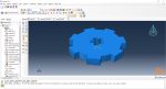
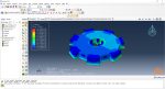
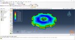
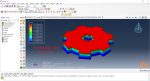
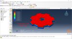
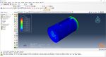
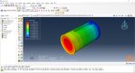
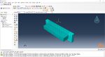
Workshop 1: 3D printing Abaqus simulation of Gear with DISP, USDFLD and Python scripting (Same cross-section)
In this workshop, first, the geometry of the model is explained. Next, the difference between continuous and discontinuous layers is discussed, which is an important issue regarding using the Python script for these kinds of examples. Then, material properties with all their equations and detail are explained, and these properties are defined using the USDFLD subroutine. Next, the boundary conditions are explained. After that, the temperature changes and their relations are discussed, which is applied to the model using the DISP subroutine. Finally, after explaining how the Python code and subroutines are written and work, the simulation will be done, and the results will be discussed.
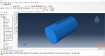
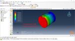
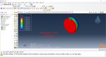
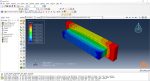
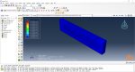
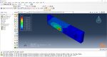
Workshop 2: 3D printing Abaqus simulation of shaft with DISP, USDFLD and Python scripting (non-uniform section)
In this workshop, like the previous one, the model’s geometry is explained at first. Next, the model layering is presented. All other stages would be like the previous workshop. The only differences are in the model’s geometry, Python code, and layers; the differences are because this model has a non-uniform cross-section.
Enroll for this advanced course to complete you education in Additive manufacturing:
“Machine Learning for Predicting Fatigue Properties in Additive Manufacturing Course”
Method 2: Using AM Modeler plug-in for additive manufacturing
The “AM Modeler” plug-in is a user-friendly interface for Abaqus additive manufacturing simulation that allows users to simulate 3D printing with minimal risk of errors. Unlike Python scripting or coding, this plug-in only requires users to input the necessary data, create a job, and start the simulation. The plug-in simulates 3D printing using two methods: eigenstrain and thermomechanical. Each method has different process types that users can choose from based on their specific needs. The eigenstrain method has two process types: trajectory-based and pattern-based, while the thermomechanical method has four process types: trajectory-based powder bed fabrication, pattern-based powder bed fabrication, laser direct energy deposition, and fusion deposition modeling. This training package focuses on the thermomechanical method.
The thermomechanical approach involves a thermal-stress analysis of an additive manufacturing process, which is performed sequentially. Initially, a heat transfer analysis is conducted, followed by a static structural analysis that utilizes the temperature fields obtained from the thermal analysis. The simulation allows for precise control over processing conditions in both time and space, resulting in a thorough and realistic solution. However, as time and spatial (mesh) resolution increase, the simulation becomes computationally expensive.
The heat transfer analysis must simulate the progressive material deposition, progressive heating of deposited material, and progressive cooling of the printed part. The stress analysis is driven by temperatures from the heat transfer analysis, and progressive material deposition methods comparable to the heat transfer analysis can be applied. Temperature-dependent material properties can be used for precise stress results.
Note: 3D printing can be used to produce complex components quickly and cost-effectively, allowing for more customization and reduced lead times, right? SO, it can be a great help in Smart manufacturing! But what is smart manufacturing anyway? Do not worry because we have a complete course of it: “Smart Manufacturing Course.”
Workshops of the second method
There are three main workshops for this method: “Sequential thermomechanical analysis of simple cube one-direction LPBF 3D printing using trajectory-based method with AM plug-in”, “Abaqus 3D printing simulation with Fusion deposition modeling and Laser direct energy deposition method with AM plug-in”, and “Material Removing with AM plug-in”. These workshops are done with two versions of the AM Modeler: an older version and a newer version; the first workshop (LPBF) is done with the older version, and the other two with the newer version. Why two versions? It’s because of you to learn how to work with them in case you have each of them.
You can watch demo here.
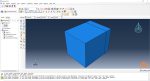
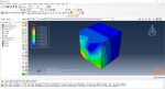
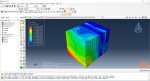
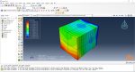
Workshop 3: Sequential thermomechanical analysis of simple cube one-direction LPBF 3D printing using trajectory-based method with AM plug-in
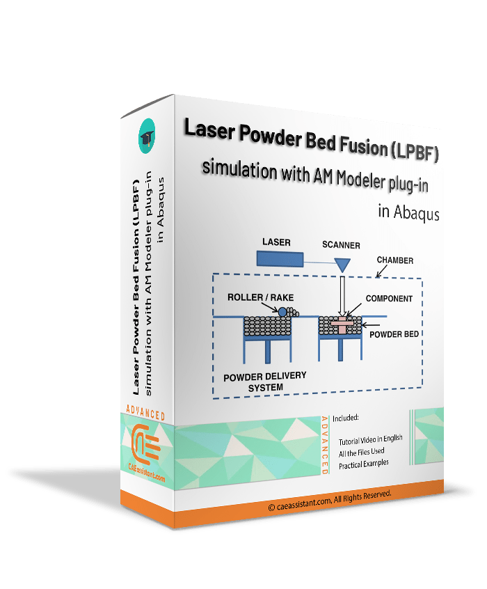
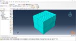
The Laser Powder Bed Fusion (LPBF) method is a 3D printing technique that uses a high-powered laser to melt and fuse metal powders together layer by layer. In Laser Powder Bed Fusion (LPBF), a layer of metal powder is spread over a build platform by a roller. A high-powered laser scans the powder, melting and fusing it together according to the 3D model. The platform is lowered, and the process is repeated layer by layer until the object is complete.
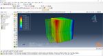
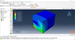
In this workshop, first, the geometry of the model and details of the layers are discussed. After presenting the required material properties, the information and required inputs of the roller and laser beam are introduced, which include their speeds and “Event series” data. Next, the boundary conditions are explained, and then, the modeling in the Abaqus begins. First, the modeling with the Abaqus/CAE is done; then, the inputs required for this simulation, like “Event series” data, will be added via AM Modeler plug-in. Two analyses must be done; first, the thermal analysis, then the structural analysis. In the end, the results will be discussed. This simulation is done using the older version of the AM Modeler plug-in.
You can get Access only to this workshop if you want through this package:
LPBF Printing Simulation in Abaqus | 3D Printing with Laser Powder Bed Fusion Process (LPBF) Method
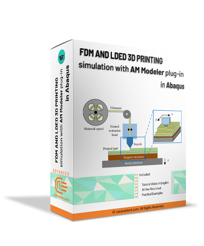
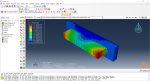
Workshop 4: Abaqus 3D printing simulation with Fusion deposition modeling (FDM) and Laser direct energy deposition (LDED) method with AM plug-in
The Fused Deposition Modeling (FDM) method is a 3D printing technique that extrudes melted filament layer by layer to create a 3D object. In this method, a filament is fed into a heated extruder (nozzle), which melts the filament and deposits it layer by layer onto a build platform according to the 3D model. The material cools and solidifies, creating the final object.
In this workshop, after presenting the model’s geometry, the layering of the model and its details, such as the dimensions of the bead, are explained. Next, the material properties are introduced. After that, the nozzle’s data, such as speed, are represented. All the simulation steps are like the previous workshop except the AM Modeler part because this workshop uses the newer plug-in version.
In both workshops, the material is first deposited using the element progressive activation technique (Material Deposition) and heated using a moving heat source. Both material deposition and moving heat source have several types, which are explained in the workshops.
You can get Access only to this workshop if you want through this package:
FDM Simulation in Abaqus | Simulating 3D Printing with Fused Deposition Modeling
Workshop 5: Material Removing with AM plug-in
This workshop introduces some special-purpose techniques and user subroutines that are available for machining and material removal processes, which often follow an additive manufacturing process. This workshop will teach you how to do a material removal process on a simple cube. This simulation is simply done by defining a bead and an event series along with required special-purpose techniques, “ABQs”. The bead is for assigning the materials that must be removed; the event series is for defining the toolpath trajectory; the ABQs are for applying them and some settings; and the progressive element activation method in a structural or a thermal analysis to deactivates the elements. To do this simulation, after the required settings are done using the AM Modeler plug-in, the input file must be generated, and then, some changes in the input file must be made manually and run the input file.
You can get access to the each method of simulation separately via the links below:
|
You can read more about Additive Manufacturing Simulation.
It would be useful to see Abaqus Documentation to understand how it would be hard to start an Abaqus simulation without any Abaqus tutorial.
All the package includes Quality assurance of training packages. According to this guarantee, you will be given another package if you are not satisfied with the training, or your money is returned. Get more information in terms and conditions of the CAE Assistant.
All packages include lifelong support, 24/7 support, and updates will always be sent to you when the package is updated with a one-time purchase. Get more information in terms and conditions of the CAE Assistant.
Notice: If you have any question or problem you can contact us.
Ways to contact us: WhatsApp/Online Support/Support@CAEassistant.com/ contact form.
Projects: Need help with your project? You can get free consultation from us here.
To access tutorial video run the .exe file on your personal pc and send the generated code to shop@caeassistat.com and wait for your personal code, which is usable only for that pc, up to 24 hours from CAE Assistant support.
Here you can see the purchase process of packages: Track Order
11 reviews for Additive Manufacturing or 3D Printing Abaqus simulation
Clear filtersYou must be logged in to post a review.
You may also like…


Python scripting in ABAQUS Part1

Introduction to USDFLD and VUSDFLD Subroutine
In this usable tutorial, the material properties can change to an arbitrary dependent variable. One of the most important advantages of this subroutine is simplicity and applicability. Various and high usage examples are unique characteristics of the training package.
This training package includes 5 workshops that help you to fully learn how to use USDFLD and VUSDFLD subroutines in Abaqus software. By means of these subroutines, you will have expertise redefine field variables at a material point by the solution dependence of standard and explicit, respectively.
cardoso –
This course is great for beginners. Taught me all the basic tools needed in for 3d printing simulation. The projects were fun to follow along and the explanations were clear.
sojong –
The 3D Printing courses was challenging and Fun. It took a lot more time for me than estimated: Great Course!
rira.sam –
Exceptional teaching course for getting introduced to simulate 3d printing with abaqus. By the end of this course I absolutely was able to create my own designs for 3d printed functional objects
marin.Hail –
This course is quite good and detailed. One thing I might add is that put some documents on the topics like some review papers or other documents.
Sophia-rotu –
I am very satisfied with this 3D printing Abaqus training package. The tutorials are comprehensive and cover everything from basic concepts to advanced simulation techniques.
Théo-mia –
hi caeassistant team, I want to say that the first method, which uses scripting and subroutines, is a great option for those who want to have more control over their simulation and customize it according to their needs also the tutorial videos explain everything in detail and make it easy to follow.
Thank you for being professional.