
Simulation Methods & Techniques
Cold Forming Simulation Using Abaqus CAE | Residual Stress Analysis
Have you ever heard of cold forming process? It refers to the reshaping of metals into desired forms at room temperature. It suits well for parts requiring high precision and a good surface finish. While cold forming offers many advantages, it is important to consider the potential for residual stresses within the material. The residual stresses in cold-formed components can influence their behavior, potentially affecting the quality of the final product. Experimentally measuring these stresses can be challenging. Numerical simulations offer a solution for cold forming residual stress analysis. Among the available numerical methods, Abaqus cold forming simulation has gained significant attention from researchers and practitioners. This training explores Abaqus cold forming analysis in detail. It includes three workshops that cover different steps in the cold forming process. For validation purposes, we have compared the results for the numerical simulation of cold forming with a reference solution for each workshop.
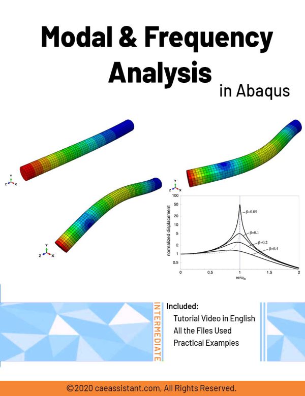

Modal and Frequency Analysis in Abaqus | Abaqus modal Analysis
Modal analysis is a technique used to understand how structures and systems vibrate when subjected to forces. It identifies natural frequencies, which are frequencies at which a system vibrates without external excitation, and mode shapes, representing unique patterns of motion. Engineers use modal analysis simulation to design systems resistant to unwanted vibrations, preventing resonance and potential damage.
Frequency response analysis evaluates a structure's reaction to specific excitations across varying frequencies, aiding in design optimization to mitigate fatigue damage caused by vibrations. In Abaqus software, Abaqus modal analysis identifies natural frequencies (Abaqus natural frequency) and mode shapes, while frequency response analysis predicts a structure's response to excitation across a frequency range.
In Abaqus modal analysis tutorial package, there are several modal analysis examples (modal analysis example): Workshop 1 analyzes the natural frequency of a water transfer tube to predict resonance occurrence or potential issues from vibrations. Workshop 2 simulates the dynamic analysis of a frame under a sudden load, determining modes, natural frequencies, and transient dynamic response.
Workshop 3 simulates free and forced vibrations of a wire under harmonic excitation, examining resonance phenomena with preloading and spring-damper configurations. These workshops demonstrate practical applications of modal and frequency response analyses in structural dynamics simulation and design.
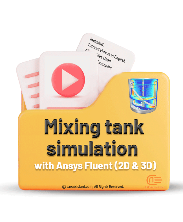
Mixing tank simulation with Ansys fluent(2D and 3D)
The mixing process is crucial and highly effective in various industrial applications. It finds application in industries such as food and cement manufacturing, among others. This course focuses on the implementation of mixing processes in both 2D and 3D spaces.
This course begins with designing the geometry with complete details. Next, we learn how to use Ansys Meshing software to mesh the geometry in detail and assess the mesh quality. Following this, we apply appropriate two-phase and turbulence models to simulate the process, allowing us to analyze the results. Additionally, we create animations of the process to visualize how the mixing process occurs.
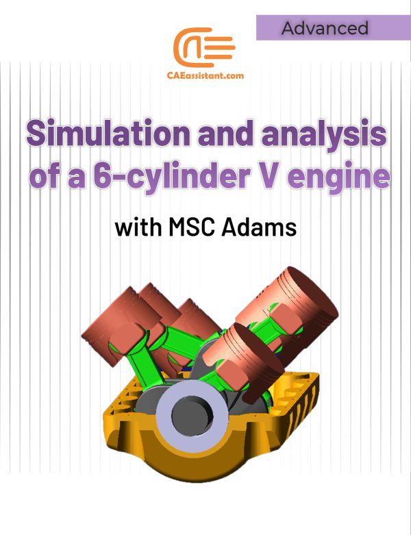
Simulation and analysis of a 6-cylinder V engine with MSC Adams
A 6-cylinder V engine is a type of internal combustion engine that features six cylinders arranged in a V-shaped configuration. This design allows for a more compact and efficient engine compared to traditional inline configurations. The cylinders are typically divided into two banks, each with three cylinders, set at an angle to each other.
The V configuration provides a more balanced and smoother operation, reducing vibrations and improving overall performance. This engine layout is commonly used in a variety of vehicles, including cars, trucks, and SUVs, due to its combination of power, efficiency, and smooth operation.
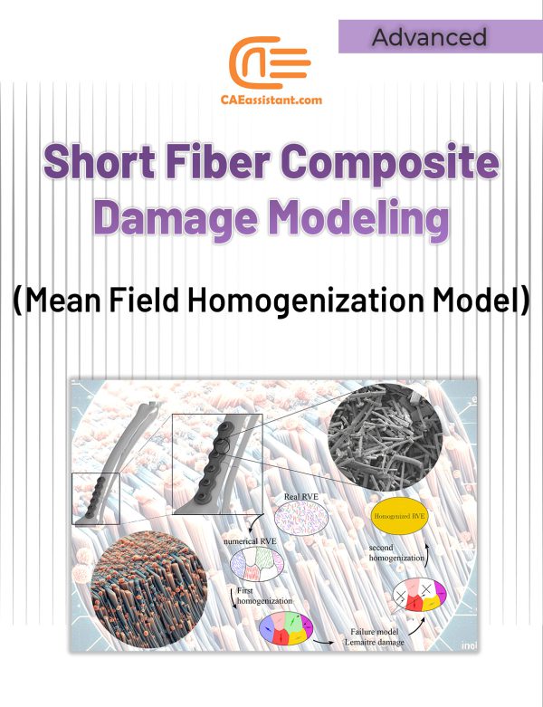
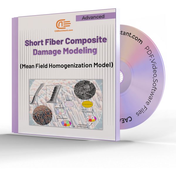
Short fiber composite damage (Mean Field Homogenization Model)
Short-fiber reinforced thermoplastics, popular due to their strength, lightness, and cost-effectiveness, are often manufactured using injection molding to create complex parts with dispersed short fibers. However, failure in these materials is complex, involving mechanisms like fiber cracking and plastic deformation. Current models for damage and failure are either macroscopic or simplified.
A new method tackles this challenge by evaluating stiffness using continuum damage mechanics with a multistep homogenization approach. This new method is called “Mean Field Homogenization”. This approach involves a two-stage process: first, the fibers are split into groups (grains). Then, mean-field homogenization is employed within Abaqus using a UMAT subroutine to average stiffness across these phases, followed by overall homogenization. This use of mean-field homogenization Abaqus simplifies the modeling of the composite's intricate geometry.
The method was validated through testing on a distal radius plate. Calibration was achieved through experiments, and the simulation was performed using Abaqus finite element software. It's important to note that the Abaqus short fiber damage mean field homogenization process was implemented within Abaqus through the INP code.
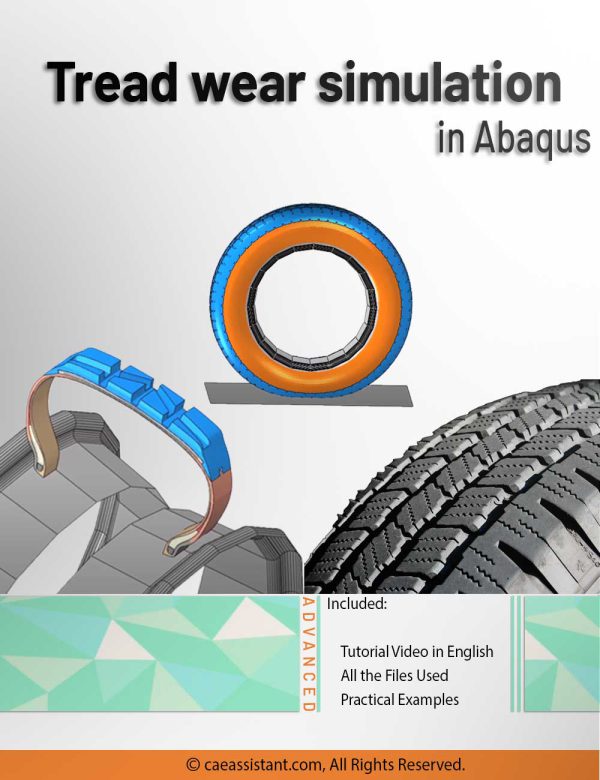
Tread wear simulation in Abaqus
This training package provides a comprehensive exploration of tire tread wear, focusing on its simulation using the UMESHMOTION subroutine in ABAQUS. Tread wear, the gradual erosion of a tire's outer rubber surface, impacts crucial performance aspects like traction and handling. The package elucidates the importance of tread wear simulation, emphasizing safety, performance optimization, regulatory compliance, durability, cost efficiency, environmental impact, and consumer confidence.
The UMESHMOTION subroutine, a key element in ABAQUS, is demystified through illustrative examples. Its application in modeling wear processes, specifically employing the Archard model, is highlighted—particularly in node movement specification during adaptive meshing.
The workshop within this package delves into simulating tire wear at a speed of 32 km/h over 1000 hours, utilizing the UMESHMOTION subroutine and Archard equations. The tire modeling process, transitioning from axisymmetric to three-dimensional elements, is detailed, considering both slip and non-slip modes of movement.
This resource serves as a valuable guide for professionals and enthusiasts seeking to understand and implement effective tread wear simulation techniques using advanced computational tools.
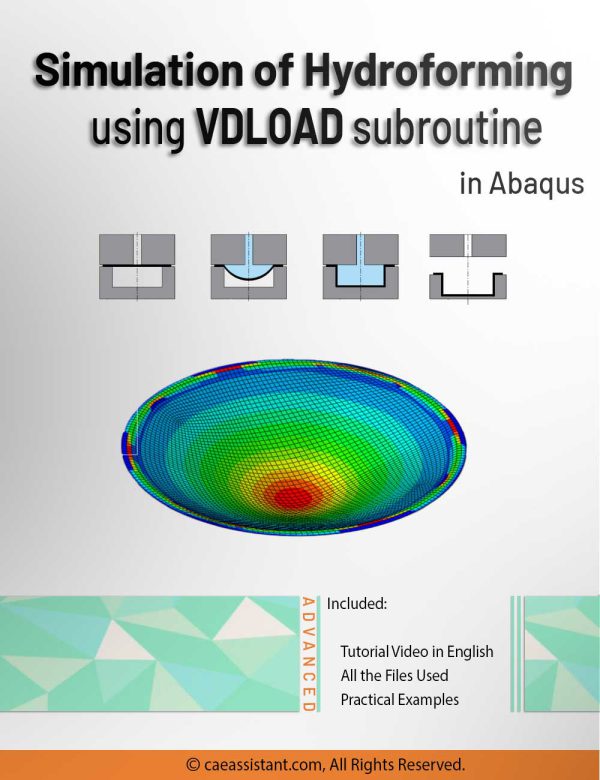
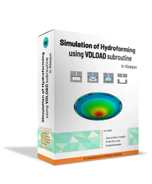
Hydroforming process simulation using VDLOAD subroutine in Abaqus
Dive into the intricacies of hydroforming simulation in Abaqus alongside the VDLOAD subroutine with our comprehensive guide. This tutorial delves into the essence of the Abaqus hydroforming simulation, unraveling the nuances of the hydroforming process simulation. Hydroforming, a specialized metal shaping technique applicable to diverse materials like steel, copper, and aluminum, is explored in depth.
In the workshop component, we specifically focus on advanced hydroforming simulation using the VDLOAD subroutine, highlighting its pivotal role in specifying fluid pressure on sheet metal forming. Learn how to apply the Functional Fluid Pressure Loading feature for precise control over fluid pressure dynamics. Additionally, explore the Smooth Amplitude option for defining part displacement seamlessly, without introducing dynamic changes during problem-solving.
Conclude your exploration with a comparative analysis of simulation outcomes, dissecting scenarios with and without fluid pressure using Abaqus hydroforming simulation. Engage in discussions on subroutine writing, delving into the intricacies of incorporating Fluid Pressure Loading into your simulations. This guide offers a natural progression through hydroforming and VDLOAD, providing valuable insights for efficient and accurate simulations.
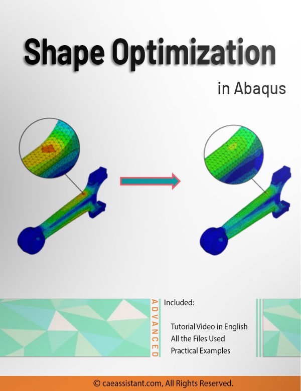
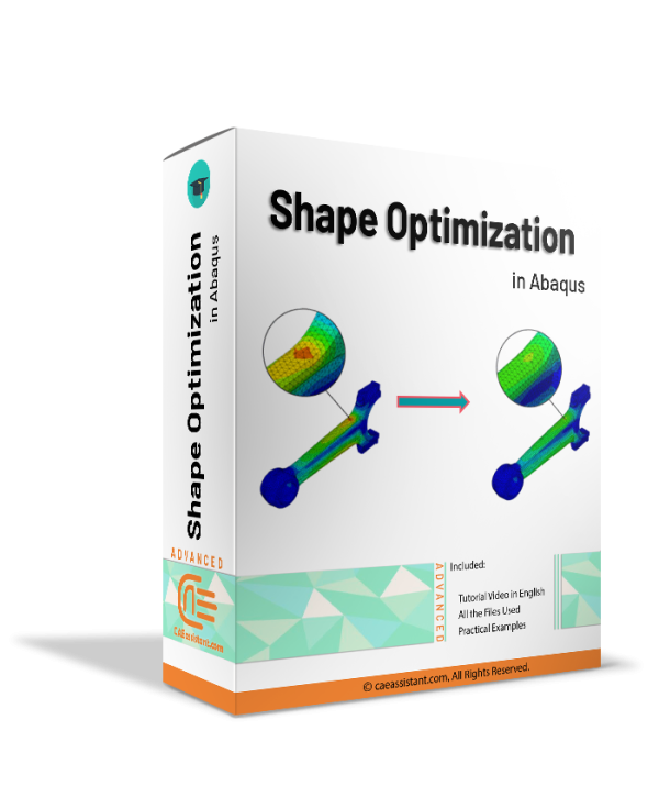
Shape optimization in Abaqus
Shape optimization is employed towards the conclusion of the design process, when the overall structure of a component is established and only minor adjustments are permitted by relocating surface nodes in specific regions. In shape optimization, the displacements of the surface nodes (design nodes) serve as the design variables. The process commences with a finite element model that requires slight enhancements or with a finite element model derived from a topology optimization. In this training package, first, you will learn the concept of optimization and shape optimization in Abaqus. After that, all required settings to do a shape optimization, such as optimization task and design responses will be fully explained. And in the last lesson, you will learn how to create an optimization process and be familiar with the generated files by the shape optimization process.
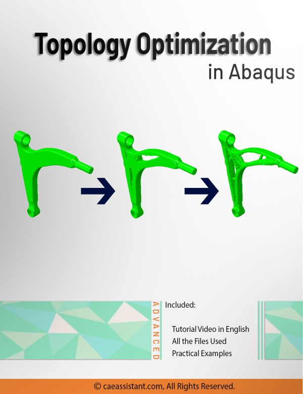

Abaqus Topology Optimization
Optimization is a fundamental concept used to enhance the effectiveness and efficiency of systems, designs, and decisions. It finds application in various domains, including industrial processes, finance, and communication networks. In engineering, optimization plays a crucial role in improving the design of systems and structures by maximizing performance and minimizing costs, weight, or other parameters. Structural optimization specifically focuses on designing or modifying structures to meet performance criteria while minimizing or maximizing objectives such as strength, weight, cost, or efficiency. The Abaqus software provides comprehensive structural optimization capabilities, including topology, shape, sizing, and bead optimization. This training package primarily focuses on Abaqus topology optimization. Through the lessons and workshops, you will gain insights into the tips, tricks, and techniques for effectively utilizing topology optimization within the Abaqus software.
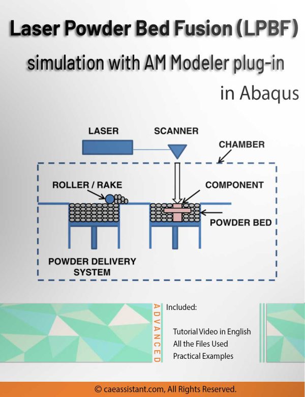
LPBF Printing Simulation in Abaqus | 3D Printing with Laser Powder Bed Fusion Process (LPBF) Method
3D printing is a process of creating three-dimensional objects by layering materials, such as plastic or metal, based on a digital design. 3D printing simulation involves using software to predict and optimize the printing process, allowing for more efficient and accurate production. This educational package includes two 3D printing modeling methods. The first method is based on the use of subroutines and Python scripting. After an introduction to the 3D printing process, the first method with all of its detail is explained; then, there would be two workshops for this method; the first workshop is for the 3D printing simulation of a gear with uniform cross-section and the second one is for a shaft with non-uniform cross-section. The second method uses a plug-in called AM Modeler. With this plug-in, the type of 3D printing can be selected, and after inserting the required inputs and applying some settings, the 3D printing simulation is done without any need for coding. Two main workshops will be taught to learn how to use this plug-in: "Sequential thermomechanical analysis of simple cube one-direction with LPBF 3D printing method using the trajectory-based method with AM plug-in" and "3D printing simulation with Fusion deposition modeling and Laser direct energy deposition method with AM plug-in".
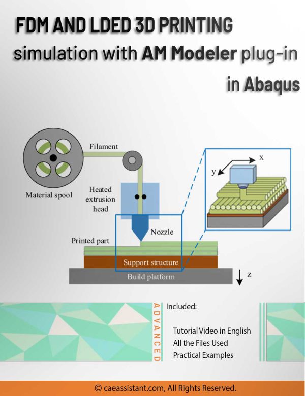
FDM Simulation in Abaqus | Simulating 3D Printing with Fused Deposition Modeling
3D printing is the process of fabricating objects in three dimensions by adding layers of materials, such as plastic or metal, based on a digital design. Simulation for 3D printing involves the use of software to predict and optimize the printing process, enabling more efficient and precise production. This educational package includes a simulation specifically for 3D printing using Fused Deposition Modeling (FDM). The FDM simulation employs a plug-in known as AM Modeler, which allows users to select the desired 3D printing method. By inputting the necessary parameters and adjusting settings, the 3D printing simulation can be performed without requiring any coding. A workshop will be conducted to teach participants how to utilize this plug-in effectively, focusing on "3D printing simulation with Fused Deposition Modeling and Laser Direct Energy Deposition method using the AM plug-in."


FSI analysis in Abaqus
Fluid-Structure Interaction (FSI) refers to the interaction between a deformable or movable structure and an internal or surrounding fluid flow. FSI simulations are vital for understanding and predicting the behavior of systems where fluid and solid components interact. These simulations enable engineers and researchers to study the effects of fluid forces on structures and vice versa.
FSI simulations are crucial in various fields, including aerospace, civil engineering, biomechanics, and automotive industries. They provide valuable insights into the performance, safety, and reliability of engineering systems. By accurately modeling the complex interactions between fluids and structures, FSI simulations can identify potential issues such as vibrations, instabilities, and structural failures.
In this package, you’ll learn simulating FSI in Abaqus within 3 workshops.
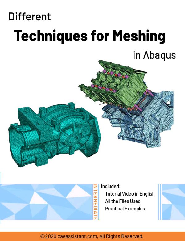
Different Techniques for Meshing in Abaqus
This package introduces different meshing techniques in Abaqus. In finite element analysis, a mesh refers to the division of a physical domain into smaller, interconnected subdomains called elements. The purpose of meshing is to approximate the behavior of a continuous system by representing it as a collection of discrete elements. Meshing is of utmost importance in finite element analysis as it determines the accuracy and reliability of the numerical solution. Through this tutorial, initially, the mesh and related terms associated with meshing are declared. Abaqus mesh module and meshing process are introduced. Then, two different meshing methodologies: Top-down and Bottom-up with meshing techniques available for each one of them are completely explained. Some of the advanced meshing techniques and edit mesh toolset are also included. The consideration of mesh verification as the final step in the meshing process, along with its criteria, is undertaken. All the tips and theories determined in this tutorial are implemented in Abaqus/CAE as a workshop to mesh several parts. This package intends to take your ability to mesh different parts to a higher level.
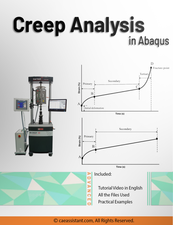

Creep Analysis in Abaqus
In engineering, creep phenomenon refers to the gradual deformation or strain that occurs in a material over time when it is subjected to a constant load or stress (usually lower than yield stress) at high temperatures. It is a time-dependent process that can lead to the permanent deformation and failure of the material if not properly accounted for in design considerations. Creep analysis is vital in engineering to understand material behavior under sustained loads and high temperatures. It enables predicting deformation and potential damage, ensuring safe and reliable structures. Industries like power generation and aerospace benefit from considering creep for long-term safety and durability of components.
In this training package, you will learn about Creep phenomenon and its related matters; you will learn several methods to estimate the creep life of a system’s components, such as Larson-Miller; moreover, all Abaqus models for the creep simulation such as Time-Hardening law and Strain-Hardening law will be explained along with Creep subroutine; also, there would be practical examples to teach you how to do these simulations.

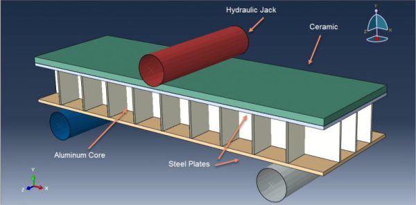
Johnson-Holmquist damage model in Abaqus
The Johnson-Holmquist damage model is used in solid mechanics to simulate the mechanical behavior of damaged brittle materials over a range of strain rates, including ceramics, rocks, and concrete. These materials typically exhibit gradual degradation under load due to the development of microfractures and typically have high compressive strength but low tensile strength. In this package, there are 13 practical examples to teach you how to use this damage model. The workshops are categorized into Ceramic materials, concrete, glass materials, and others.
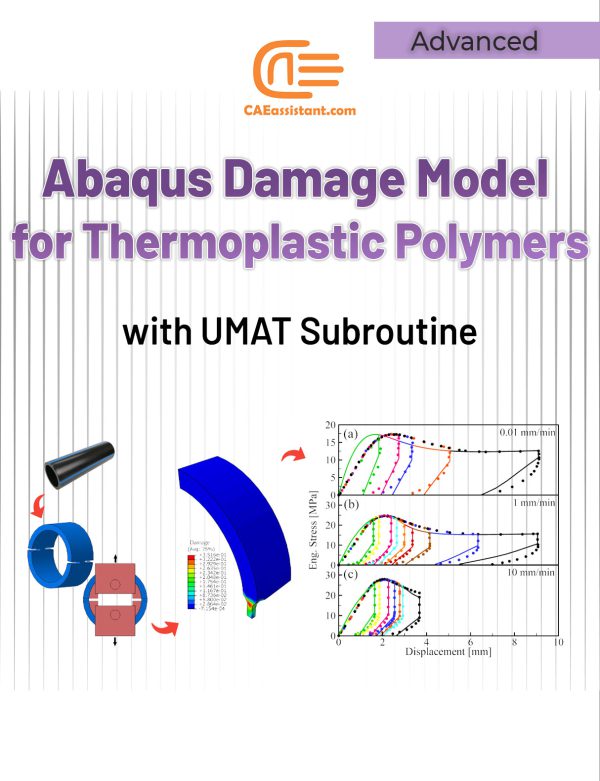
Damage Properties of Thermoplastic Polymers with UMAT Subroutine
Thermoplastic polymers are materials composed of long molecular chains primarily consisting of carbon. These polymers possess the unique ability to be shaped and molded under heat and pressure while retaining their stability once formed. This high formability makes them widely used in various industries, including furniture production, plumbing fixtures, automotive components, food packaging containers, and other consumer products. This package introduces a thermodynamically consistent damage model capable of accurately predicting failure in thermoplastic polymers. The implementation of this model is explained through the use of an ABAQUS user material (UMAT) subroutine.
The package is structured as follows. The introduction section Provides an overview of thermoplastic polymers and their mechanical properties. In the Theory section, the constitutive damage model and its formulation are reviewed. Then, an algorithm for numerically integrating the damage constitutive equations is presented in the Implementation section. In the UMAT Subroutine section, a detailed explanation of the flowchart and structure of the subroutine is provided. Finally, two simulation examples, namely the T-fitting burst pressure test and the D-Split test, are performed and the obtained results, are investigated.
Notice: Software files and A full PDF guideline (Problem description, theory, ...) are available; Videos are coming soon.
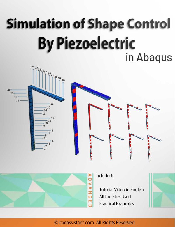
Simulation of shape control by piezoelectric in Abaqus
Piezoelectricity refers to the accumulation of electric charge in certain solid materials due to mechanical pressure. This phenomenon, known as the piezoelectric effect, is reversible. Some materials exhibit direct piezoelectricity, which involves the internal production of electric charge through the application of mechanical force, while others exhibit the inverse piezoelectric effect.
By harnessing piezoelectrics, it becomes possible to control the geometrical changes of objects in response to external forces. However, it is important to note that utilizing this property in all situations would not be cost-effective. Therefore, it is more practical to use piezoelectric structures selectively, specifically in special applications. One approach to determining the optimal placement of piezoelectric elements for controlling the geometric shape of various objects under internal or external forces involves utilizing the Abaqus and MATLAB software linkage. This software combination, along with optimization algorithms such as the particle swarm optimization algorithm, can be employed to achieve the desired objectives. By leveraging these tools and data, the primary goal of controlling object shape can be successfully accomplished.
In this training package, you will learn about piezoelectric and piezoelectric modeling in Abaqus, the particle swarm optimization algorithm, linking Abaqus and MATLAB, and how to use these tools for shape control.
Notice: Software files and A full PDF guideline (Problem description, theory, ...) are available; Videos are coming soon.
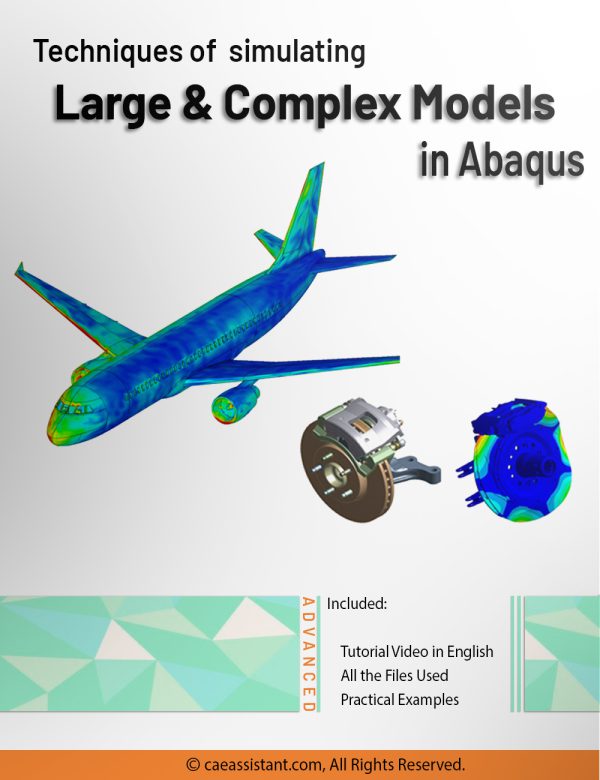
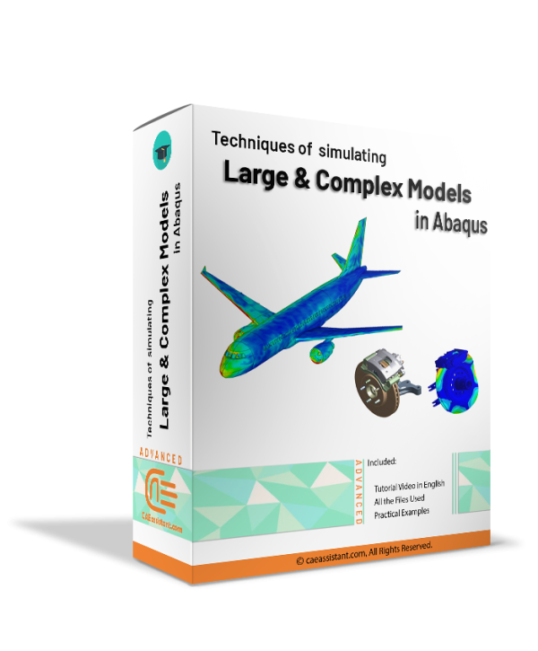
Techniques of simulating Large and Complex models in Abaqus
Sometimes, there is a need to simulate large or complex models in Abaqus, such as airplanes and cars. Generally, models with more than 5 million variables or take at least 12 hours to analyze are considered large. Processing such models requires a significant amount of time and energy, in addition to potential issues with modeling, loading, boundary conditions, and more. Therefore, it is necessary to find ways to simplify and accelerate the analysis of such models.
In this training package, you will learn various methods to address these challenges. Dealing with large models typically involves simplifying the model, making efficient use of system resources, and minimizing CPU time. These techniques are explained in detail here. Additionally, you will be taught various techniques to aid in the management of large models, including submodeling, history output filtering, restart functionality, and parts and assemblies.
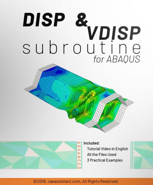
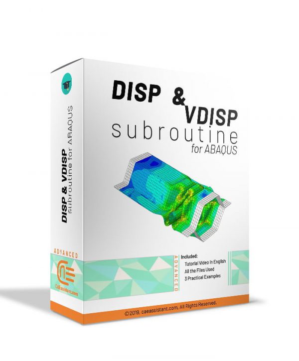
DISP and VDISP Subroutines in ABAQUS
In a very simple form, DISP and VDISP subroutines are used to define user-defined boundary conditions. For example, when you need to define a boundary condition to be time-dependent, location-dependent, or even both, you should use the DISP and VDISP subroutines. ABAQUS features cannot be sufficient for problems with location-dependent and time-dependent boundary conditions simultaneously. In these cases, this subroutine can be useful to solve the challenges. In This package, you will understand the usages of these subroutines and how to work with them in three conceptual and simple workshops.
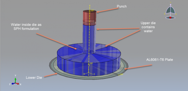
Hydroforming simulation in Abaqus
Notice: This package will be available one week after purchase.
Hydroforming is a metal forming process that allows the shaping of various metals, such as steel, stainless steel, copper, aluminum, and brass. It is a cost-effective and specialized form of die molding that utilizes highly pressurized fluid to shape the metal. Hydroforming can be classified into two main categories: sheet hydroforming and tube hydroforming. Sheet hydroforming uses a single die and a sheet of metal, while tube hydroforming involves expanding metal tubes using two die halves. Hydroforming simulation in Abaqus is a valuable tool for optimizing the hydroforming process. It enables engineers to predict and analyze important factors such as material flow, stress distribution, thinning, and wrinkling during the forming process. By accurately simulating the hydroforming process, engineers can optimize key parameters like fluid pressure, die design, and material properties to achieve the desired shape with minimal defects. In this package, you will learn hydroforming process simulation with the SPH method and using time-pressure curve.
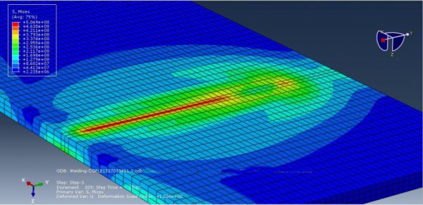
Arc welding simulation in Abaqus
Arc welding is a fusion process that involves joining metals by applying intense heat, causing them to melt and mix. The resulting metallurgical bond provides strength and integrity to the welded joint. Arc welding is widely used in various industries for fabricating structures and components. Arc welding simulation in Abaqus is essential for optimizing the welding process and ensuring high-quality welds. It allows engineers to predict and analyze factors such as temperature distribution, residual stresses, distortion, and microstructure evolution during welding. By accurately simulating the welding process, parameters like welding speed, heat input, and electrode positioning can be optimized to achieve desired weld characteristics and minimize defects.
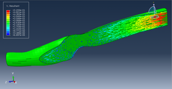
Blood Flow Analysis in Abaqus
Human blood is a vital fluid that circulates through the body, carrying oxygen, nutrients, hormones, and immune cells. Simulation of human blood is crucial for understanding cardiovascular diseases, hemodynamics, and therapeutic interventions. It enables researchers to study the complex behavior of blood flow, investigate disease mechanisms, and develop improved diagnostic and treatment strategies. This package contains three workshops that would help you simulate blood flow in vessels: “Human blood with coronary vessel Fluid Structure Interaction simulation in Abaqus”, “Blood and vessel FSI simulation using Abaqus-Co Simulation process”, and “Non-Newtonian blood flow Simulation in Abaqus”.
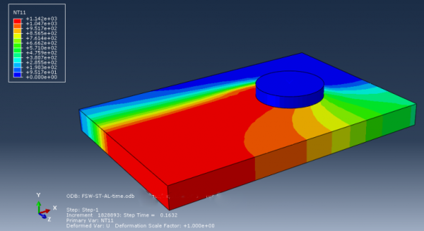
Friction Stir Welding (FSW) Simulation in Abaqus
Friction stir welding (FSW) is a solid-state joining process that utilizes a rotating tool to generate frictional heat, enabling the consolidation of materials without melting. FSW offers numerous benefits and is particularly valuable for welding challenging materials like aluminum alloys. It finds widespread applications in industries such as automotive, aerospace, shipbuilding, and construction, providing enhanced strength, weight reduction, and structural integrity. FSW minimizes distortion, reduces the need for post-weld machining, and eliminates issues related to solidification and cooling. Simulations using Abaqus, a popular finite element analysis software, play a crucial role in optimizing FSW processes. Engineers can investigate process parameters, evaluate weld quality, predict residual stresses and distortions, and optimize weld designs through Abaqus simulations. These simulations enable cost-effective development, improved weld quality, reduced material waste, and enhanced productivity in industrial applications. In this package, you will learn how to simulate FSW simulations in a variety of examples with different methods.

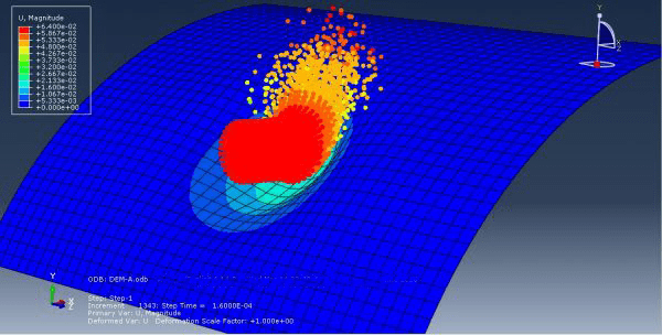
Soil Impact Analysis in Abaqus
Soil impact refers to the interaction between a solid object and the soil, wherein the object collides with or penetrates into the soil. This issue holds great importance across various industries, including civil engineering, geotechnical engineering, construction, and transportation. Understanding soil impact behavior is crucial for designing and assessing the safety and performance of structures and systems subjected to dynamic loads, such as vehicle collisions, pile driving, and projectile impacts. Simulation plays a vital role in studying soil impact. By employing advanced numerical methods and software tools like Abaqus, researchers and engineers can accurately model and analyze the complex interactions between objects and soil. Simulation allows for the investigation of various parameters, such as impact velocity, soil properties, object geometry, and boundary conditions, to assess their influence on the response and behavior of the system. In this package, you will learn how to do soil impact simulations in several practical examples.