


Analysis of filament wound Composite Pressure Vessel(CPV).
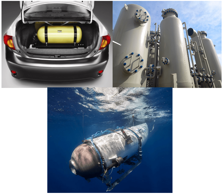
Due to their importance and applications in various industries, such as storing gases and fuels, pressure vessels are developed with different manufacturing methods. This package explains the winding methods for making the composite pressure vessel. It also presents the equations of planar winding, geodesic winding, and isotensoid winding with complete details and parameter definitions. These equations are about the winding angle and thickness in various parts of the vessel. This training package covers the complete analysis of the composite pressure vessel.
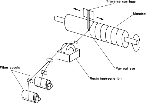
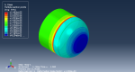
As you know, the winding simulation is the most important issue because the angle and thickness are changed in different portions of the dome. One way to simulate CPVs is to partition the dome of the vessel. Then, we should assign the calculated thickness and angle to the dome. To achieve an accurate result, we should create a lot of partitions, especially in the end dome, because the angle and thickness change instantaneously in this region. On the other hand, we need to do many simulations to find the best composite pressure vessels, and the partition method takes a lot of time. So, we use Python scripting to fix this problem and quickly simulate many CPV with precise results. This training package contains Python scripting for automatic modeling and UMAT subroutine with Fortran language to detect progressive Puck failure.
Workshop 1: Simulation planar composite pressure vessel with Abaqus GUI
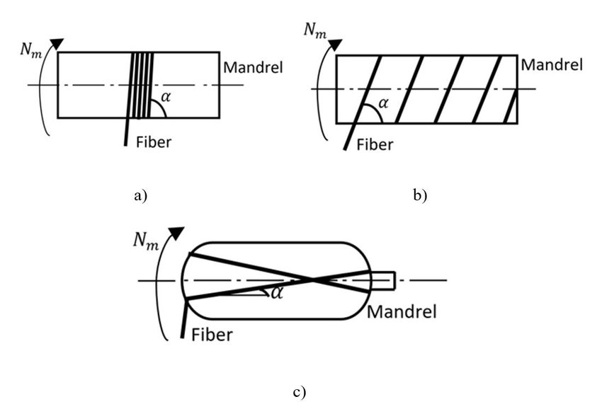
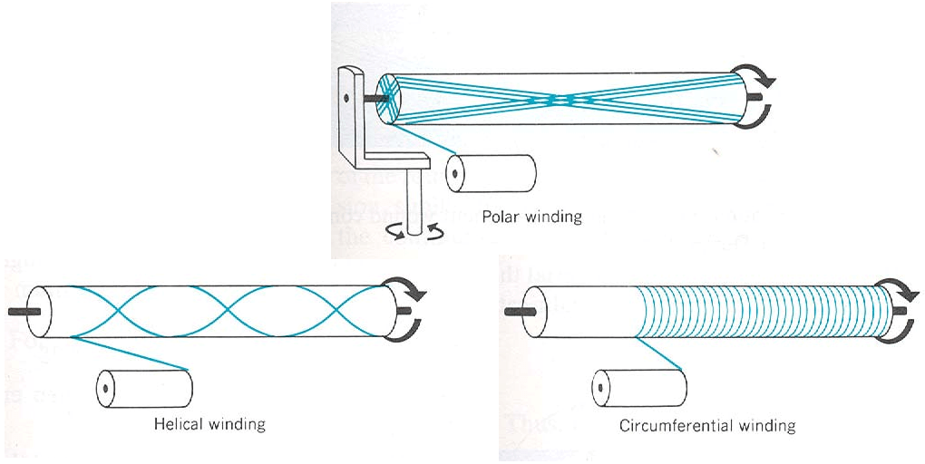
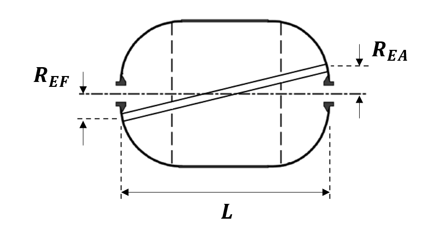
First, in workshop 1, we simulate a composite pressure vessel made using the planar winding. We use the Abaqus graphical user interface (GUI) to simulate this vessel. To use the GUI, first, because the winding angle and thickness change along the vessel dome, we need to divide the dome into many partitions to apply these changes. Then, using a Matlab program, we calculate the winding angle and thickness for each partition of the dome. To better understand the Matlab program, a flowchart of it is presented. After that, we manually perform the layering in Abaqus for each partition of the dome. Also, to model the composite damage in this simulation, we use the Tsai-Hill model.
Workshop 2: Automatic Simulation of Geodesic composite pressure vessel with Python script
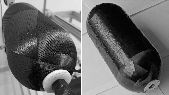
This workshop simulates the composite pressure vessel with geodesic winding patterns in Abaqus finite element software. As mentioned, the vessels are simulated using a Python program, and the method of writing and using this program is fully taught. This Python script helps you to automatically simulate a pressure vessel without using the Abaqus graphical user interface(GUI) by simply entering the relevant dimensions of the vessel. As a result, with this program, you no longer need to draw the vessel and perform the other simulation steps in the Abaqus software. Additionally, a flowchart is prepared and presented to better understand the process of the Python script.
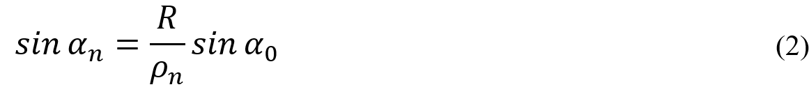
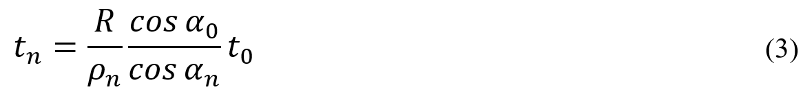
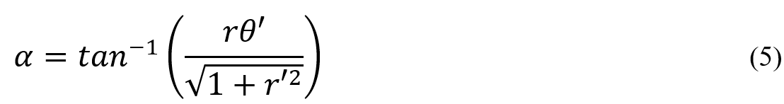
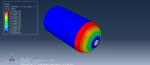
It should be mentioned in this method for calculating the winding angle we need to examine the path of fiber movement on the dome and determine the forces applied on the fibers at each point. So, by examining the path of fiber and the forces applied to it, we can calculate the winding angle and thickness at any point of the vessel. This is also done by the Python script. Also, the Python program allows assigning the calculated thickness and winding angle to each element based on its coordinates. In the final section of this workshop, for example, a pressure vessel is simulated using the Python script and the Tsai-Hill failure criterion. The results of this simulation, including the stress distribution in the vessel, are shown.
Workshop 3: Automatic Simulation of Isotensoid composite pressure vessel with Python script
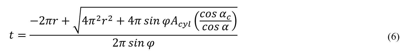
Isotensoid filament winding is very similar to the geodesic method. The winding angle and thickness are calculated exactly the same as the geodesic method, but the difference between this method and the geodesic method is in the shape of the mandrel. In the isotensoid method, there are two important assumptions: first, the pressure is only tolerated by the fibers, and second, all fibers bear the pressure equally. Although these assumptions do not happen in practice, we can achieve them to an acceptable extent. Considering these assumptions in the stress analysis calculations of thin-walled vessels, we can obtain an equation determining the dome contour. Solving this equation in the Python script requires adding a mathematical model, which is also explained in this workshop. Like the previous workshops, the winding process, determining the thickness, and reviewing the results is done in this workshop. And it is available to you.
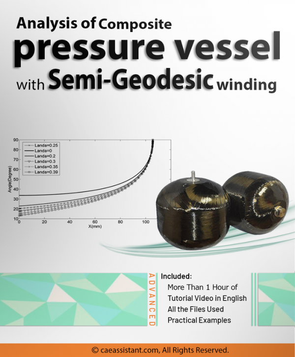
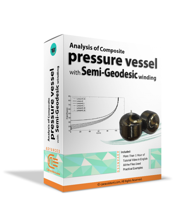
Certainly, you can use the Analysis of Composite pressure vessel with Semi-Geodesic winding package to learn about another method of fiber winding for designing pressure vessels.
Workshop 4: Failure analysis of composite pressure vessel with Puck criterion using UMAT subroutine
The Puck failure theory is selected and introduced as the best criterion to identify failure initiation among the different failure theories. The Puck criteria help identify the many lamina failure mechanisms and quantify the impact of each type of failure on the laminate. In the following, the equations of this criterion are extracted. The Puck criterion establishes specific parameters that determine the inter-fiber failure, also exposing the potential modes of failure for a given fiber under applied loads. The Puck theory identifies fiber failure in two distinct modes: fiber failure in tension(FFT) and fiber failure in compression(FFC) and provides a separate formulation for each mode. Additionally, this theory also predicts three different failure modes for matrix failure. The first mode is inter-fiber failure in tension(IFFA) with a fracture angle of zero. The second mode is inter-fiber failure in compression with a fracture angle of zero(IFFB). And the third mode is an inter-fiber failure in compression with a non-zero fracture angle(IFFC), which the Puck theory can also determine.
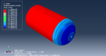
In the next step, all failure modes predicted by the Puck criterion are implemented using the UMAT subroutine. In this package, different parts of the UMAT subroutine and how to use it are well explained using Abaqus software documentation. Generally, in this subroutine, we seek to calculate the stiffness matrix and stress matrix in each increment by entering the required equations and inputs to execute the Puck theory. By using the Puck criterion, this subroutine can calculate the reduced stiffness matrix if the conditions for any of the fiber failure modes are met. Additionally, a flowchart is prepared and presented to better understand the process of the UMAT subroutine. In the final section of Workshop 4, the same pressure vessel that was simulated using the Tsai-Hill criterion in Workshop 1 and workshop 2 is simulated again, this time using the Puck criterion. The results of this simulation for different fiber failure and inter-fiber failure modes, based on the Puck theory, have been shown. For better and more comprehensive learning of the UMAT subroutine, you can use the UMAT Subroutine (VUMAT Subroutine) introduction package.
If you need more information about this package, please contact us via online chat on the left side of this page. Also, all the files used in this package will be available to you. After purchase, you can access the Python, Matlab, Abaqus, and subroutine files.
It would be helpful to see Abaqus Documentation to understand how it would be hard to start an Abaqus simulation without any Abaqus tutorial.
Moreover, the general description of how to write a subroutine is available in the article titled “Start Writing a Subroutine in Abaqus: Basics and Recommendations “. If you even do not familiar with the FORTRAN, you can learn the basics via this article: “Abaqus Fortran “Must-Knows” for Writing Subroutines”. You may also like this article to begin writing your own UMAT: “Start Writing Your First UMAT in Abaqus”.
In comparison to metals, composites’ damage mechanisms are less well known. Composite materials and structures are susceptible to defects, whether they appear during material processing, component fabrication, or in-service use. Understanding how the damage or defect affects the structural integrity of the composite component is crucial to determining how critical the defect is. If we can somehow determine these damages and tend to them in time, the maintenance cost would be severely decreased. Also, our design will be better and well-optimized.
It’s true that the composite structures have sufficient strength and stiffness but like other structures, they may get damaged during the service. The damages could be caused by impact, low resistance to the service environment, overloading, Staff carelessness, etc.
In-service damages include:
- Impact damage
- Fatigue
- Cracks
- Delamination
- Fiber fracturing
- …
Service flaws in composite structures are typically caused by impact damages. Delamination is the most frequent impact-related damage. Delamination occurs when layers in a laminated composite are split, creating a mica-like structure with a considerable loss in mechanical properties. Delamination is the separation of the laminate at the boundary between two layers as a result of shock, impact, or repeated cyclic pressures. Individual fibers can pull away from the matrix, for instance.
It is the engineer’s duty to analyze the structures and determine the defects and damages so that the structure can keep working properly and lower the cost of maintenance. With the help of Computer-aided engineering (CAE) and finite element method (FEM), you would be able to do this task in the best way possible.
We are here at the CAE Assistant to explain some about composite material damage and introduce some FEM tools to simulate these damages correctly. Also, we will help you out learn how to simulate and analyze your model and structure. With our high-quality education, you can learn how to work with the Abaqus and analyze composite structures. I recommend you read the topics of this training package on the right side of this page and if you have more questions about this package and its content and quality, ask on the live chat on the left side of this page.
Read More: All about Abaqus composite material
Users ask these questions
In social media, users asked questions regarding pressure vessels simulation, composite pressure vessel modeling, etc., and related things such as filament winding production method modeling. So, we decided to answer some of them, which you can see them below:
I. Modeling a pipe with composite stack
Q: I attempted modeling a filament wound pipe in 3D in Abaqus, but I couldn’t achieve the proper stacking direction, which is along the pipe thickness and the hoop or Theta direction. Any suggestions on how to go about it?
A: Hello,
First, you need to partition your model. It depends on your composite. Then, create a coordinate system for each partition in which they can move and rotate with the partition. In this way, you can set your direction correctly. Or for filament winding you can write a Python code like we did in this tutorial:
“Composite Pressure Vessel simulation in ABAQUS”
In this tutorial, three winding methods, planar, geodesic, and isotensoid, have been taught for filament winding pressure vessels using Python script.


dufort –
According to the description, this package almost covers any necessary information. Don’t you have any free version of this package?