Sayed Ali

Showing all 4 results

Our products

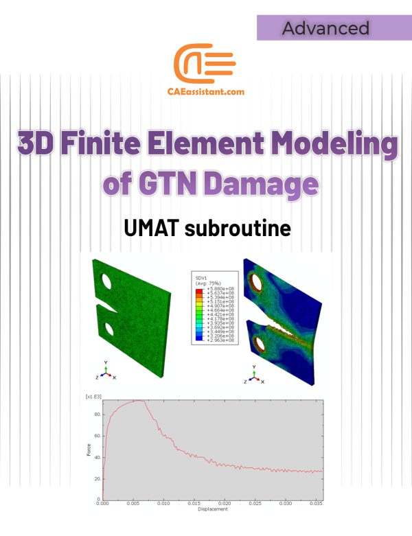
3D Simulation of Gurson-Tvergaard-Needleman (GTN) Damage Model

 190.0
The GTN (Gurson-Tvergaard-Needleman) damage model is a robust continuum damage model used to simulate ductile fracture in materials. It accounts for porosity, a key damage parameter, to predict material behavior under various loading conditions. The model's benefits include comprehensive fracture analysis, accurate damage prediction, versatility, and enhanced simulation capabilities. Despite these advantages, implementing the GTN model in software like Abaqus (GTN model Abaqus) is challenging. It is due to the need for custom subroutines, such as VUMAT. However, writing the subroutine requires proficiency in Fortran programming and an understanding of finite element analysis. This project provides a detailed guide for using the VUMAT subroutine to define the GTN model in Abaqus. It addresses challenges like high computational costs and the need for extensive experimental data. The tutorial demonstrates the model's application in material design, failure analysis, structural integrity assessment, research and development, and manufacturing process simulation. By exploring stress distribution, nodal temperatures, and displacement fields, the project aims to enhance the understanding and predictive capabilities of the GTN damage model.

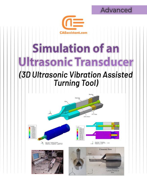
Simulation of an Ultrasonic Transducer (3D Ultrasonic Vibration Assisted Turning Tool)

 190.0

Since the invention of ultrasonic vibration assisted turning, this process has been widely considered and investigated. The reason for this consideration is the unique features of this process which include reducing machining forces, reducing wear and friction, increasing the tool life, creating periodic cutting conditions, increasing the machinability of difficult-to-cut material, increasing the surface quality, creating a hierarchical structure (micro-nano textures) on the surface and so on. Different methods have hitherto been used to apply ultrasonic vibration to the tip of the tool during the turning process. In this research, a unique horn has been designed and constructed to convert linear vibrations of piezoelectrics to three-dimensional vibrations (longitudinal vibrations along the z-axis, bending vibrations around the x-axis, and bending vibrations around the y-axis). The advantage of this ultrasonic machining tool compared with other similar tools is that in most other tools it is only possible to apply one-dimensional (linear) and two-dimensional (elliptical) vibrations, while this tool can create three-dimensional vibrations. Additionally, since the nature of the designed horn can lead to the creation of three-dimensional vibrations, there is no need for piezoelectric half-rings (which are stimulated by a 180-phase difference) to create bending vibrations around the x and y axes. Reduction of costs as well as the simplicity of applying three-dimensional vibrations in this new method can play an important role in industrializing the process of three-dimensional ultrasonic vibration assisted turning.

In this example, how to model all the components of an ultrasonic transducer and its modal and harmonic analysis are taught in full detail.

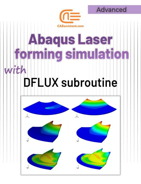
Laser forming simulation tutorial in Abaqus

 120.0
(1)
The laser forming process is performed by applying thermal stresses to the workpiece surface by heating the surface with a laser beam. These internal stresses induce plastic strains in the part resulting in local elastic-plastic deformation (Laser-induced plastic deformation). In this laser forming simulation tutorial the DFLUX subroutine is used to apply heat flux (Gaussian heat distribution) dependent on location and time in finite element simulation. For example, the linear heating processes of laser forming and welding (with a slight simplification) can be simulated by this subroutine. In the linear heating process, by applying heat flux to the surface of a sheet, a thermal gradient is created in its thickness. This thermal gradient causes permanent deformation of the sheet. To simulate the laser forming process, it is necessary to apply a time and location-dependent heat flux to the sheet. In this type of loading, a heat flux is applied on the plate, which is defined using the DFLUX subroutine, including the laser power, movement speed, beam diameter, absorption coefficient, and laser movement path according to the designed experiments (Laser forming process parameters). To verify this Abaqus laser forming simulation, the simulation results and experimental results of sheet deformation (U) are compared. The displacement of the sheet in the simulation is in good agreement with the experimental results.

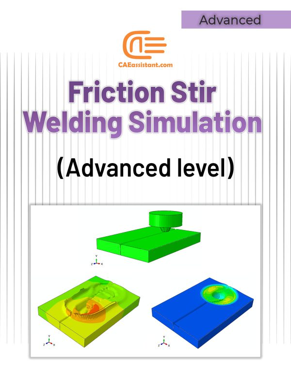
Friction Stir Welding simulation Tutorial | FSW Advanced level

 100.0
(1)
Friction stir welding (FSW) involves complex material flow and plastic deformation. Welding parameters, tool geometry, etc., have important effects on the material flow pattern, heat distribution, and eventually on the structural evolution of the material. In an Abaqus friction stir welding example, the rotational movement of the tool and its friction in contact with the workpiece causes heat generation, loss of strength, and an increase in material ductility around the tool. The feeding movement of the tool causes the material to transfer from the front of the tool to the back of it, and eventually leads to a join. Therefore, heat plays an important role in this process, and parameters such as rotational speed, tool feeding speed, tool geometry, and others, all somehow have a significant impact on controlling the amount of incoming heat, the disturbance and flow pattern of the material, the evolution of the microstructure, and the quality of the resulted weld. This friction stir welding example simulation tutorial shows you how to simulate the Abaqus FSW simulation process in such a way that you can accurately predict the effect of all relevant parameters on the process. In most of the implemented projects, welding mud, and welding defects (welding overfills and overlaps, weld gaps) are not visible and predictable; however, in this simulation, these cases are visible. This project is designed to enhance participants' understanding of how to accurately simulate the FSW process to see the weld's general appearance.