ABAQUS
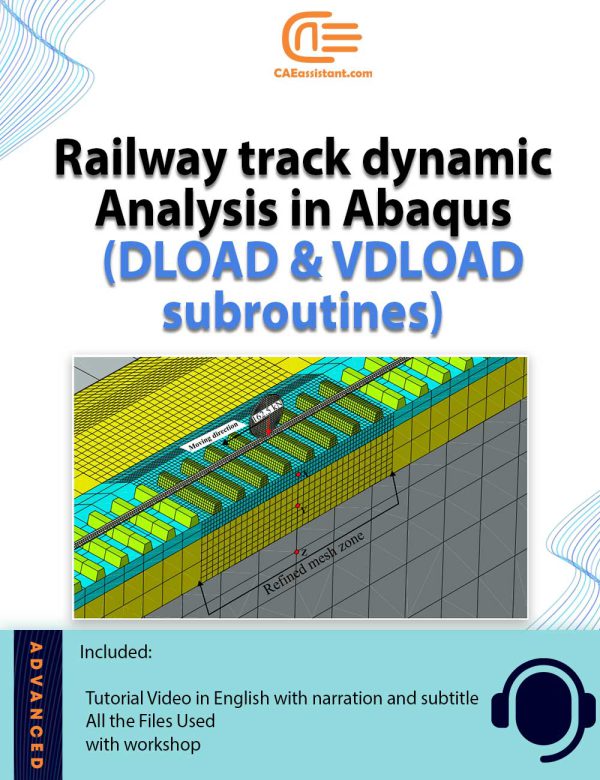
Dynamic Response of Ballasted Rail Track Under a Moving Load
Railway tracks are subjected to moving loads of trains and this causes vibration and degradation of the track. The judgment of these vibrations is important to design the railway tracks. The design involves the permissible speed of trains and the maximum axle load of the train. The model given here creates a 3D geometry of a railway track and applies a moving load in the form of a wheel. A user can change the speeds and the properties of the material including geometry as per their needs.
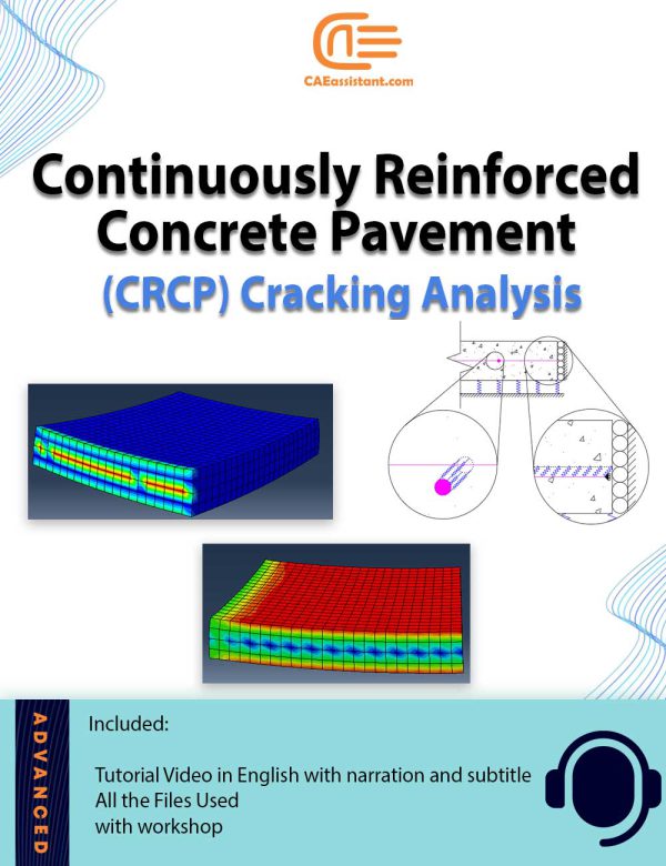
Continuously Reinforced Concrete Pavement (CRCP) Cracking Analysis
|
The increasing adoption of continuously reinforced concrete pavement (CRCP) in highway pavement design is driven by its demonstrated superior performance. Critical to evaluating the long-term effectiveness of CRCP is the understanding of early-age cracks (CRCP crack analysis), which has garnered significant interest from highway departments. This Abaqus Continuously reinforced concrete pavement modeling project aims to establish precise design parameters for CRCP and analyze the formation of crack patterns. By accounting for stress factors such as environmental conditions and CRCP shrinkage modeling, the project offers valuable insights into predicting the likelihood of crack initiation and propagation within the concrete slab. These insights are instrumental in enhancing the durability and performance of CRCP structures, thus advancing the efficiency and effectiveness of highway infrastructure. |
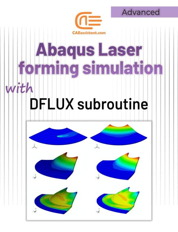
Laser forming simulation tutorial in Abaqus

Friction Stir Welding simulation Tutorial | FSW Advanced level
Sloshing Simulation in Cylindrical Water Storage Tanks: An Abaqus Modeling Framework
Cold Forming Simulation Using Abaqus CAE | Residual Stress Analysis
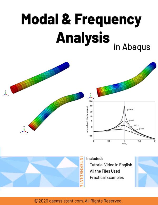

Modal and Frequency Analysis in Abaqus | Abaqus modal Analysis
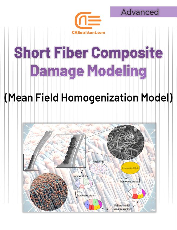
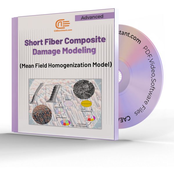
Short fiber composite damage (Mean Field Homogenization Model)
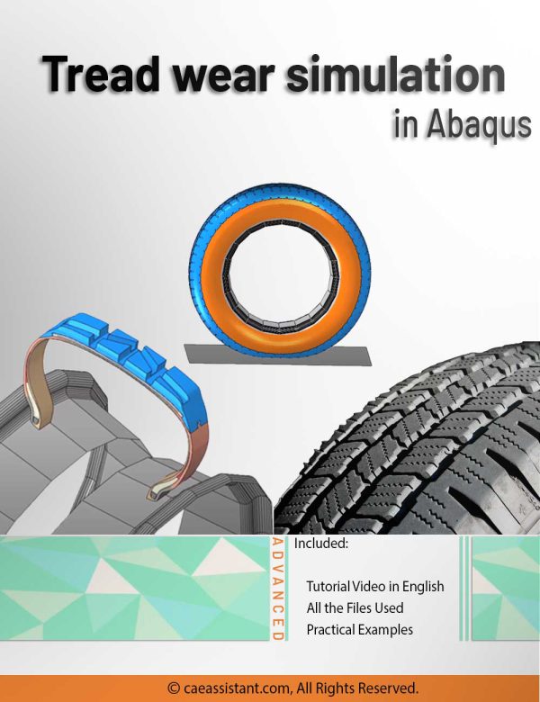
Tread wear simulation in Abaqus
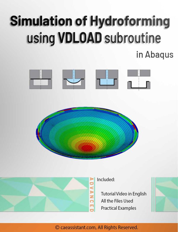
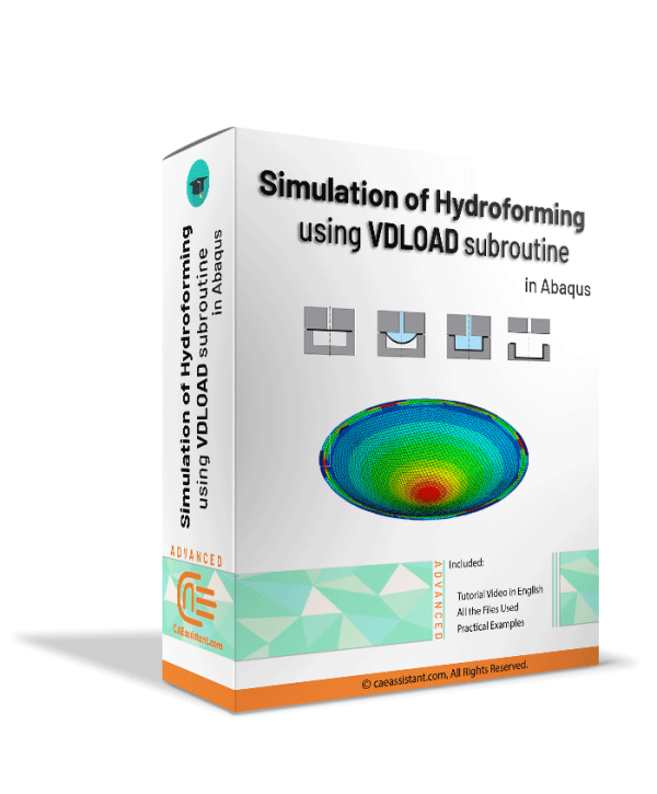
Hydroforming process simulation using VDLOAD subroutine in Abaqus
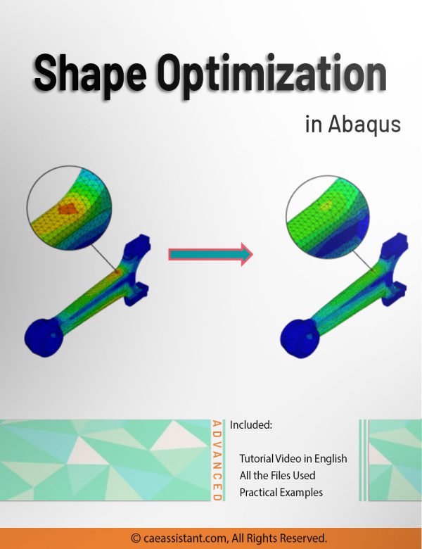
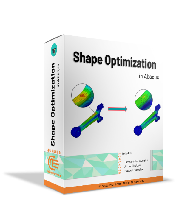
Shape optimization in Abaqus
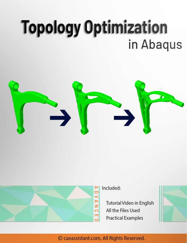

Topology Optimization in Abaqus
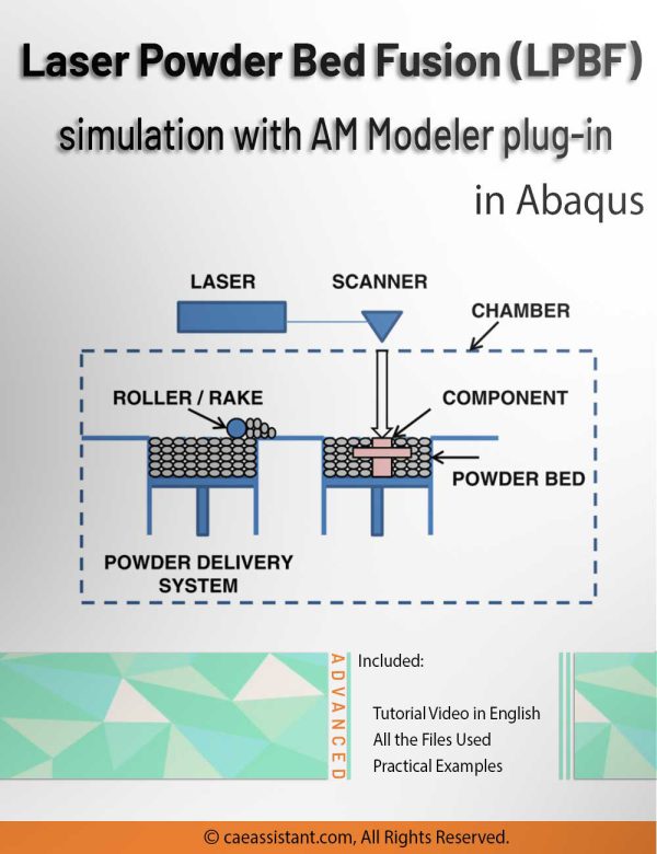
3D printing simulation with Laser Powder Bed Fusion (LPBF) method in Abaqus
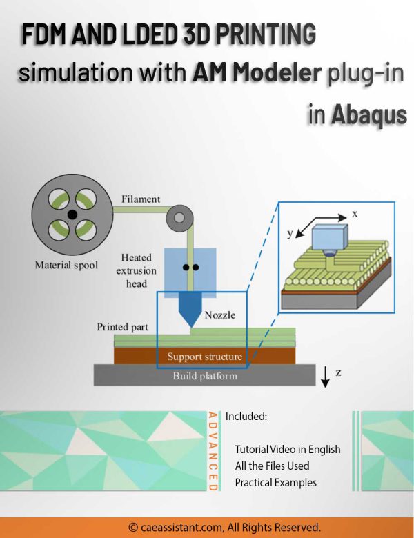
3D printing simulation with Fused Deposition Modeling (FDM) in Abaqus
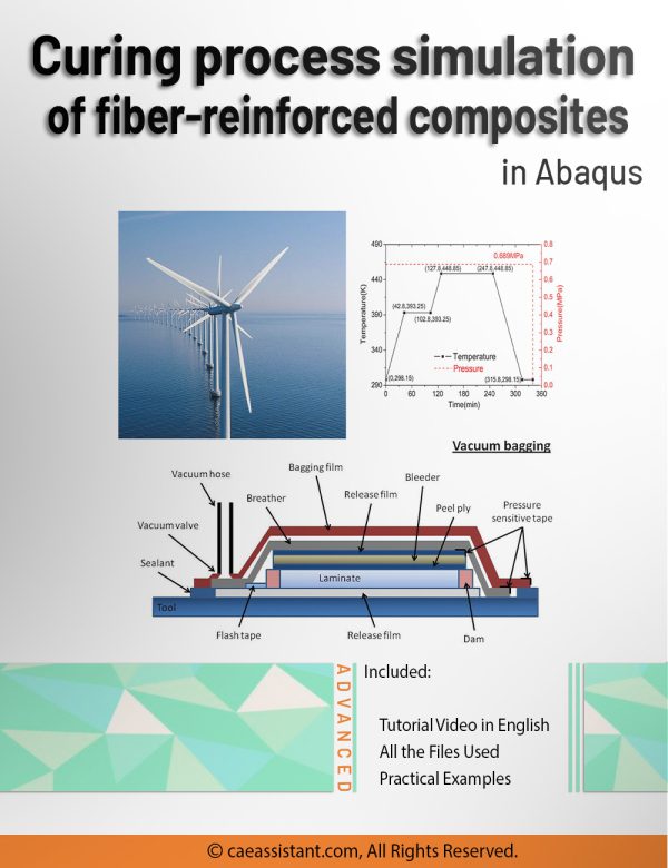
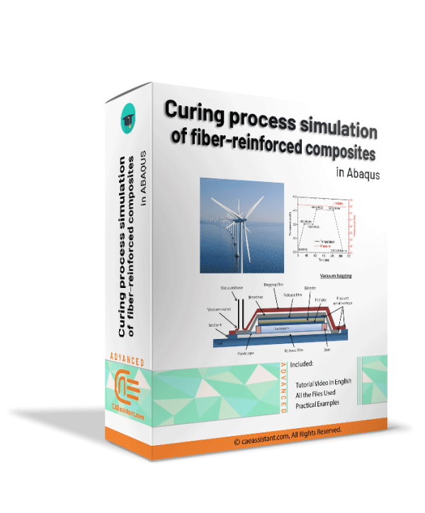
Curing process simulation in Abaqus


FSI analysis in Abaqus
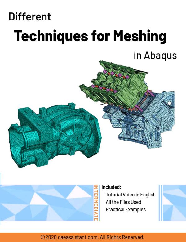
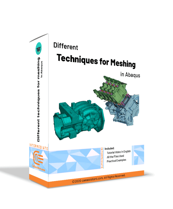
Different Techniques for Meshing in Abaqus
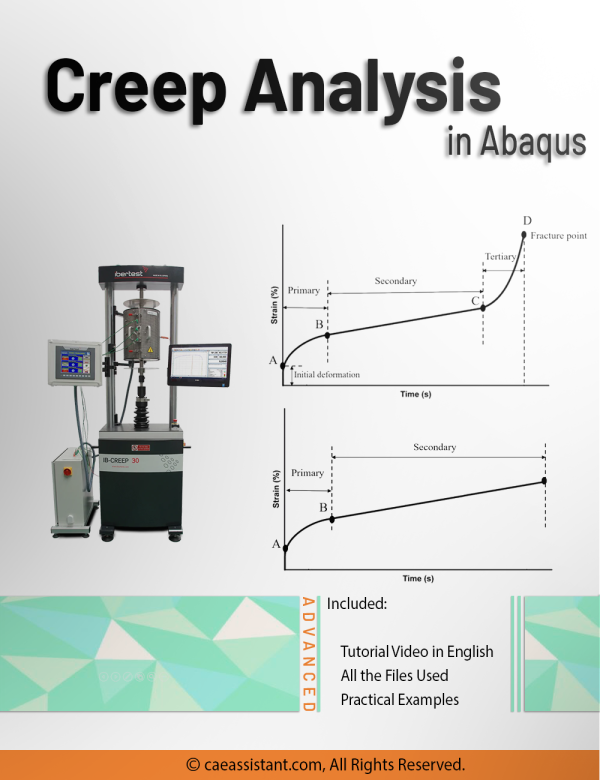

Creep Analysis in Abaqus

Johnson-Holmquist damage model in Abaqus
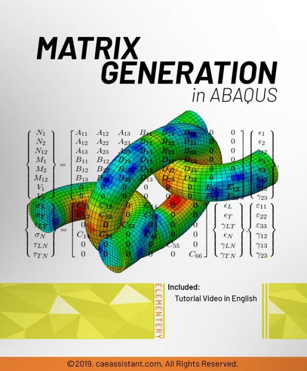
Matrix Generation in ABAQUS
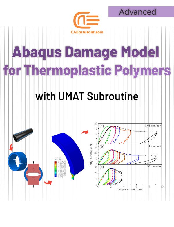
Abaqus Damage Model for Thermoplastic Polymers with UMAT Subroutine
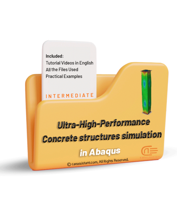

Ultra-High Performance Concrete (UHPC) structures simulation in Abaqus
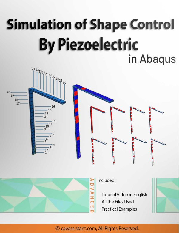
Simulation of shape control by piezoelectric in Abaqus
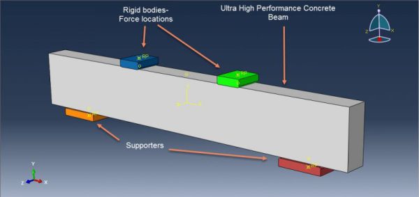
Ultra-High Performance Concrete (UHPC) beams simulation in Abaqus
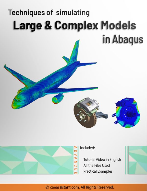
Techniques of simulating Large and Complex models in Abaqus
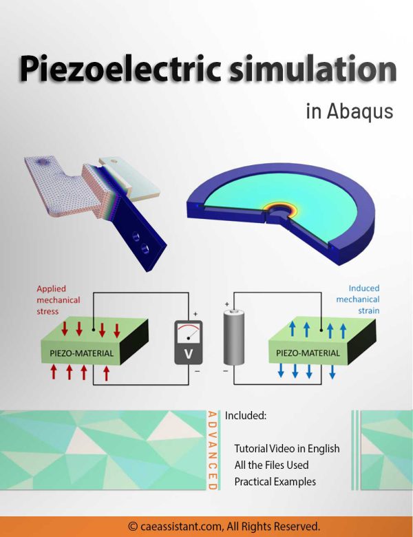

Piezoelectric simulation in Abaqus


Abaqus for Civil Engineering Part-1
DISP and VDISP Subroutines in ABAQUS
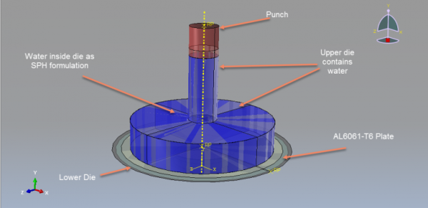
Hydroforming simulation in Abaqus
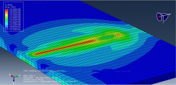
Arc welding simulation in Abaqus
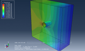
Tunnel excavation simulation using TBM in Abaqus
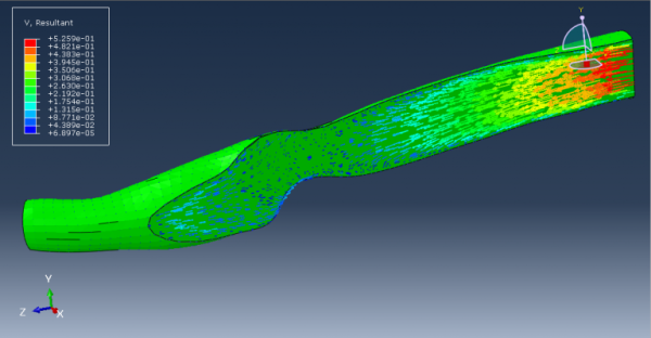
Blood Flow Analysis in Abaqus
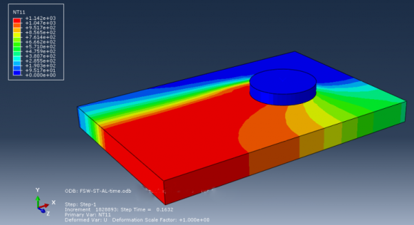
Friction Stir Welding (FSW) Simulation in Abaqus

Simulation of Hyperelastic Behavior of Materials

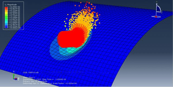
Soil Impact Analysis in Abaqus
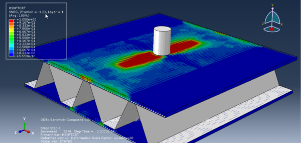
Low-Velocity Impact simulation in Abaqus
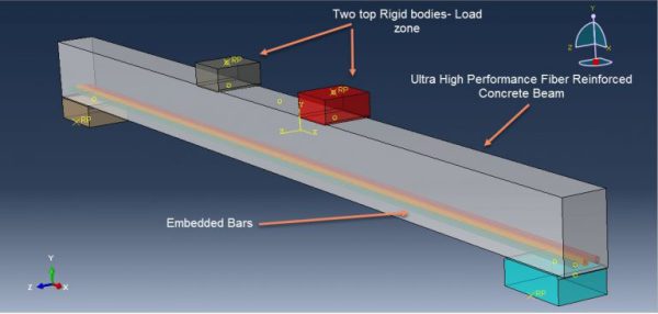
Ultra-High-Performance Fiber Reinforced Concrete (UHPFRC) structures in Abaqus
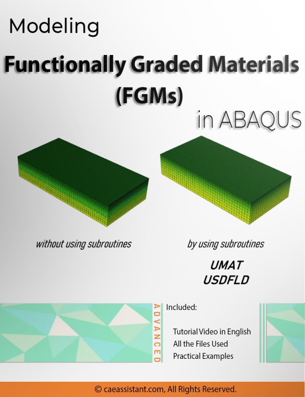
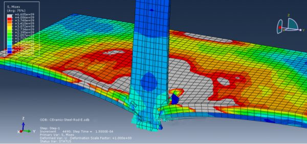
Modeling Functionally Graded Materials (FGMs) in ABAQUS

High-Velocity Impact Simulation in Abaqus
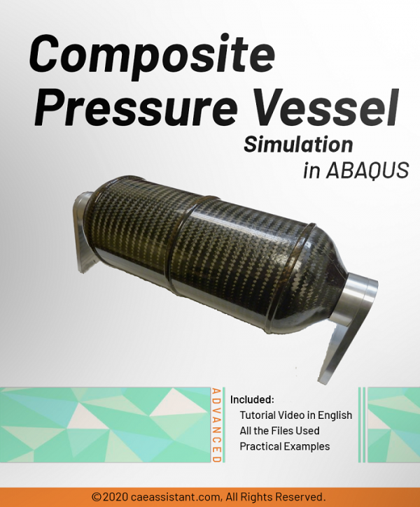
Composite Pressure Vessel simulation in ABAQUS
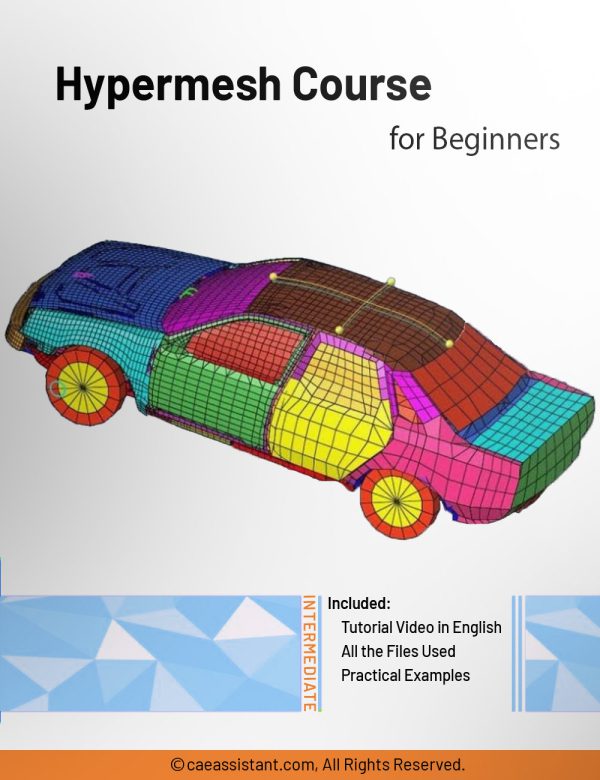
Hypermesh Course for Beginners
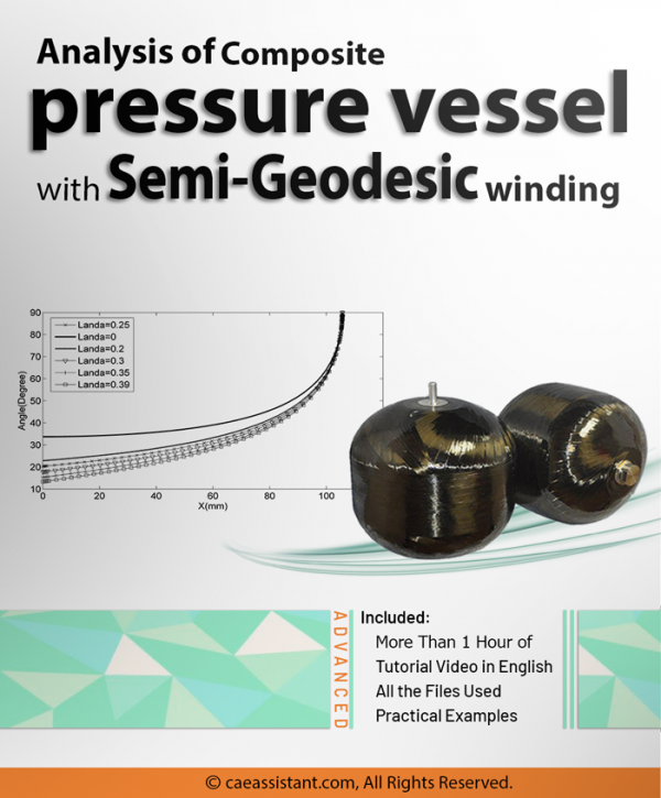
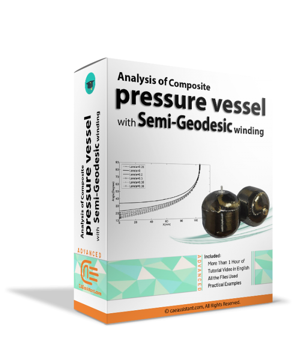
Composite pressure vessel analysis with Semi-Geodesic winding
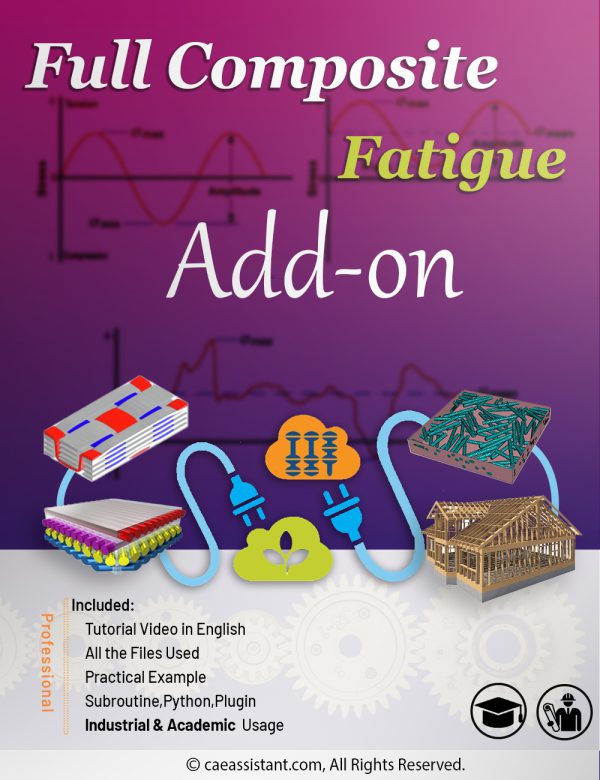
Full Composite fatigue Add-on (Academic and industrial usage)